
Automating Pick-and-Place Lines: Selecting the Right Hybrid Stepper Motor Architecture
Pick-and-place automation is a synchronization problem before it is a motor problem. A machine that transfers a part across a gantry, lowers it on a vertical axis, rotates a gripper and then indexes a conveyor is running several different motion tasks at the same time — each with its own stroke, payload, duty cycle, precision expectation and holding requirement.
Sizing every axis with the same motor type is the most common architecture error in this segment. The workable approach is to select an architecture per axis, then confirm that motor, driver and controller are electrically matched as one system. This guide maps the mechanical and electrical requirements of pick-and-place equipment onto hybrid stepper motor architectures, using the product families and published specifications of ACT MOTOR — Changzhou ACT Motor Co., Ltd., a manufacturer of hybrid stepper motors, stepper motor drivers, geared motors and linear-actuator motor assemblies — as the reference platform.

The Pick-and-Place Motion Problem: Several Axes, One Control Cabinet
A hybrid stepper motor is a permanent-magnet stepper design that indexes in discrete angular steps and is driven by pulse signals rather than continuous commutation. ACT MOTOR's hybrid range covers step angles from 0.9° to 2.4°, which suits stop-and-go pick-and-place duty. The difficulty is that one pick-and-place machine contains several structurally different axes:
- X-Y transfer axis — medium or long stroke, high cycle rate, moderate moving mass, frequent reversals.
- Z placement axis — short stroke, vertical load, must hold position during dwell and must not creep when idle.
- Rotary gripper axis — small angular moves with high torque relative to available space, usually through a reduction stage.
- Feeder or conveyor axis — continuous indexing, moderate accuracy, tolerance to changing load.
Because those four axes behave differently, the selection criteria also differ. In practice, a pick-and-place architecture decision has to resolve six requirement categories before any model number is chosen:
- Positioning structure — is the move rotary or linear, and does it need a screw or belt interface?
- Torque and speed profile — how much holding torque is needed at the worst point of the cycle, and how fast must the axis travel?
- Duty cycle and heat — continuous multi-shift operation raises thermal requirements well above intermittent duty.
- Holding behaviour — a vertical axis needs either mechanical holding or a brake motor when power is removed.
- Electrical integration — the driver's voltage window and continuous output current must envelope the motor's rated values.
- Compliance and documentation — CE, RoHS and ISO 9001 evidence for the destination market.
Getting the first four right determines whether the machine works. Getting the last two right determines whether it can be shipped, installed and supported.
Industry Background: Why Hybrid Stepper Motors Fit Short-Move, High-Cycle Automation
Hybrid stepper motors are the dominant motor type in the stepper segment, and the segment itself is expanding. Market Research Future estimated the global stepper motor market at USD 3.962 billion in 2024, projected to reach USD 6.245 billion by 2035 at a CAGR of 4.22%. KBV Research reported that hybrid stepper motors accounted for approximately 53.93% of total stepper motor market value in 2025, and Mordor Intelligence placed Asia Pacific at a 48.91% share of the market in the same year, supported by a USD 36.9 billion semiconductor-equipment spend in China. Precedence Research valued the high-torque stepper motor market specifically at USD 1.15 billion in 2024, with hybrid designs holding the dominant segment share.
The technical reasons for that position are practical rather than promotional. A hybrid stepper axis indexes in defined increments, is commanded by a pulse/direction interface, produces high torque at low speed where pick-and-place axes actually operate, and holds position at standstill. For a placement head executing thousands of short moves per hour, those characteristics reduce the engineering effort required in the controller.
The limits matter just as much. Open-loop stepper torque falls away as speed rises, and an axis that is accelerated too aggressively under a heavy load can lose steps. That risk is explicitly recognised in industrial applications, where requirements such as "no step loss at high speed" and "accurate start-stop control, no step loss" appear as stated project conditions. Closed-loop hybrid stepper variants exist precisely to answer this constraint.
Sources: Market Research Future, KBV Research, Mordor Intelligence, Precedence Research (stepper motor and high-torque stepper motor market data, 2024–2025).
Mapping Pick-and-Place Requirements to Hybrid Stepper Motor Architectures
Architecture 1 — Direct-drive hybrid stepper motors for the X-Y transfer axis
The X-Y gantry is the axis where a direct-drive hybrid stepper motor is usually the correct starting point. ACT MOTOR's standard hybrid stepper range covers models from 8HS and NEMA8 sizes up through 11HS, 14HS/HM, 15HS/HM, 16HS/HM, 17HS/HM, 23HS/HM/HY, 24HS, 34HS/HM/HY/HD, 42HS, 52HS and the 17HT, 23HT, 34HT, 42HT and 50HT series. Across that range the catalogue states a step angle of 0.9° to 2.4°, motor length of 34 mm to 220 mm, rated voltage of 2 V to 8 V, rated current of 0.5 A to 8 A, phase resistance of 0.05 Ω to 10 Ω, phase inductance of 0.1 mH to 10 mH, and holding torque of 0.08 N·m to 28.0 N·m.
That span is wide enough to cover both a light, fast transfer head and a heavier gantry carrying a multi-nozzle tool. The selection rule is to size for the torque required at the acceleration point of the move, not for average load, and then check that the frame size still fits the carriage envelope. Oversizing a transfer axis does not increase accuracy; it increases moving mass and heat.
Architecture 2 — Lead screw and ball screw actuators for the Z placement axis
A vertical placement axis converts rotary motion into a short linear stroke, and the cleanest way to do that is to buy the conversion as part of the motor. ACT MOTOR's lead screw stepper motor family covers models 8HSL, 11HSL, 14HSL, 15HSL, 16HST, 17HSL, 23HSL, 24HSL and 34HSL. The ball screw family covers 8HSL, 11HSL, 14HSL, 16HST, 17HSL, 23HSL, 34HSL and the geared variants 11HSLG, 14HSLG, 17HSLG, 23HSLG and 34HSLG, with a step angle of 0.9° to 1.8°, rated voltage of 12 V to 110 VDC, rated current of 0.5 A to 8 A, phase resistance of 0.05 Ω to 10 Ω, phase inductance of 0.1 mH to 10 mH and holding torque of 0.08 N·m to 28.0 N·m.
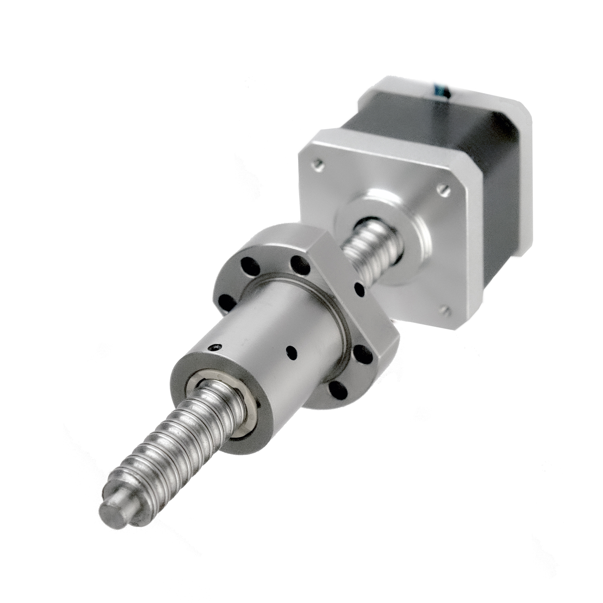
Two trade-offs belong in the decision. A screw-driven axis gains mechanical stiffness and repeatable positioning, but it also gains a mechanical component whose lead defines speed-versus-resolution. Where the Z axis must remain immobile with power removed, a brake stepper motor (available in 17HS, 23HS and 34HS frames) is the explicit solution rather than relying on the drive alone.
Architecture 3 — Geared stepper motors and gearboxes for gripper rotation and high-torque axes
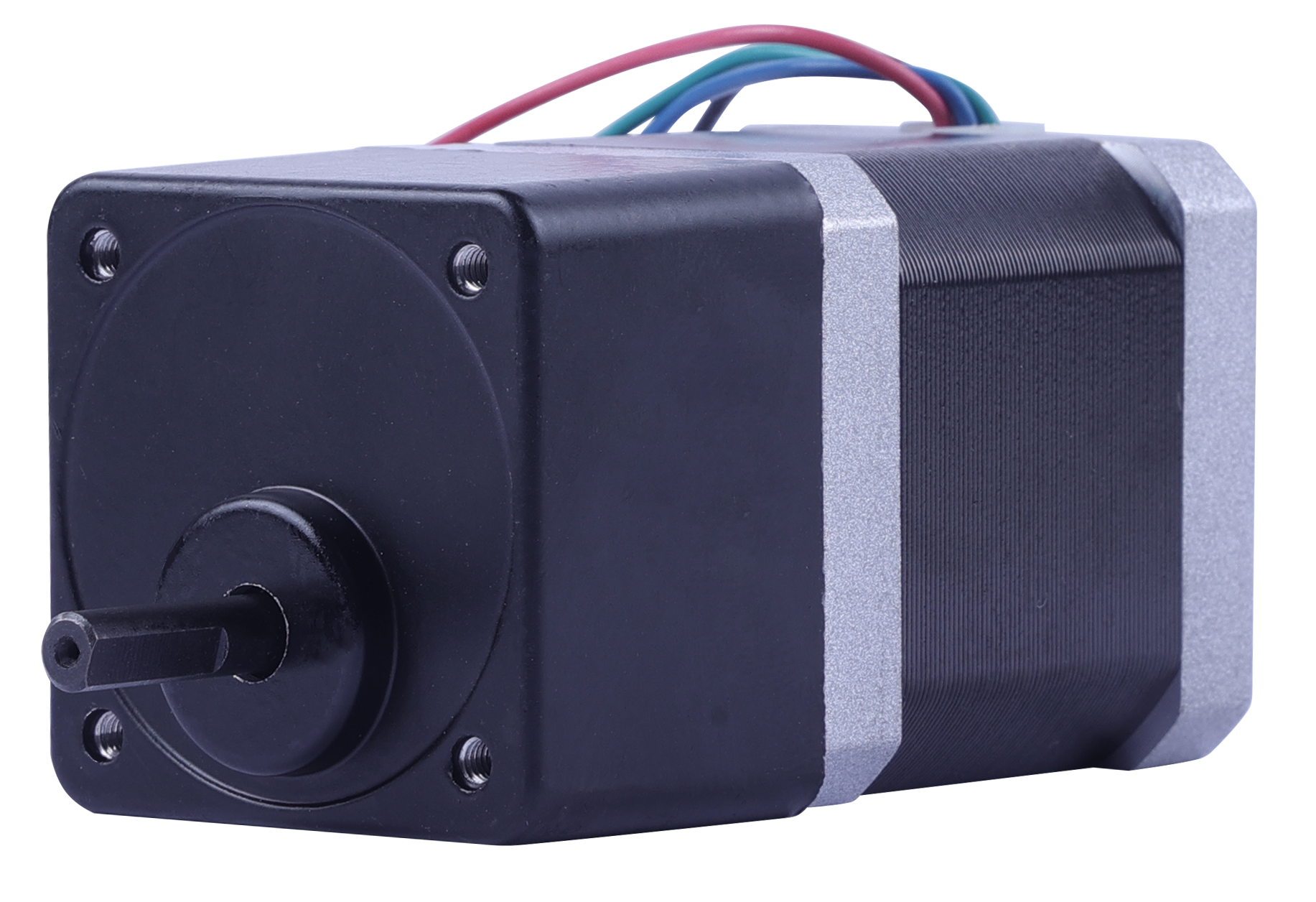
Rotary gripper axes rarely have the space for a large frame motor, so torque is obtained through reduction instead. ACT MOTOR's geared stepper motors cover 8HSAG, 11HSAG, 14HSAG, 17HSAG, 23HSAG, 34HSAG and 42HSAG with a 1.8° step angle, motor length of 28 mm to 156 mm, rated voltage of 12 V to 110 VDC, rated current of 0.5 A to 8 A, holding torque of 0.08 N·m to 28.0 N·m and reduction ratios from 1:3 to 1:512. The catalogue distinguishes precision planetary reduction gearboxes, economical planetary reduction gearboxes, RV reduction gearboxes and eccentric reduction boxes.
The engineering trade-off is straightforward: reduction multiplies available output torque and lowers the effective speed, but it also adds an interface with its own inertia and tolerance, and it makes the axis longer. A gripper that only needs to rotate between two fixed orientations may not justify a gearbox at all; one that must hold a heavy end-effector against gravity usually does.
Architecture 4 — Closed-loop stepper motors and encoders for dynamic axes
Where an axis must accelerate hard, run continuously, or operate under a load that varies from cycle to cycle, the open-loop assumption becomes the constraint. ACT MOTOR's hybrid closed-loop stepper motor family covers 8SSM, 11SSM, 14SSM, 23SSM, 24SSM, 34SSM and 42SSM with a 1.8° step angle, motor length of 33 mm to 171 mm, rated voltage options of 12–110 VDC, 18–80 VAC and 220 VAC, rated current of 0.5 A to 8 A and holding torque of 0.08 N·m to 28.0 N·m. Integrated closed-loop units in the catalogue include 23SSM8440-EC1000, 34SSM1460-EC1000, 34SSM1460-EC1000-S4 and 11SSM5409-EC800.
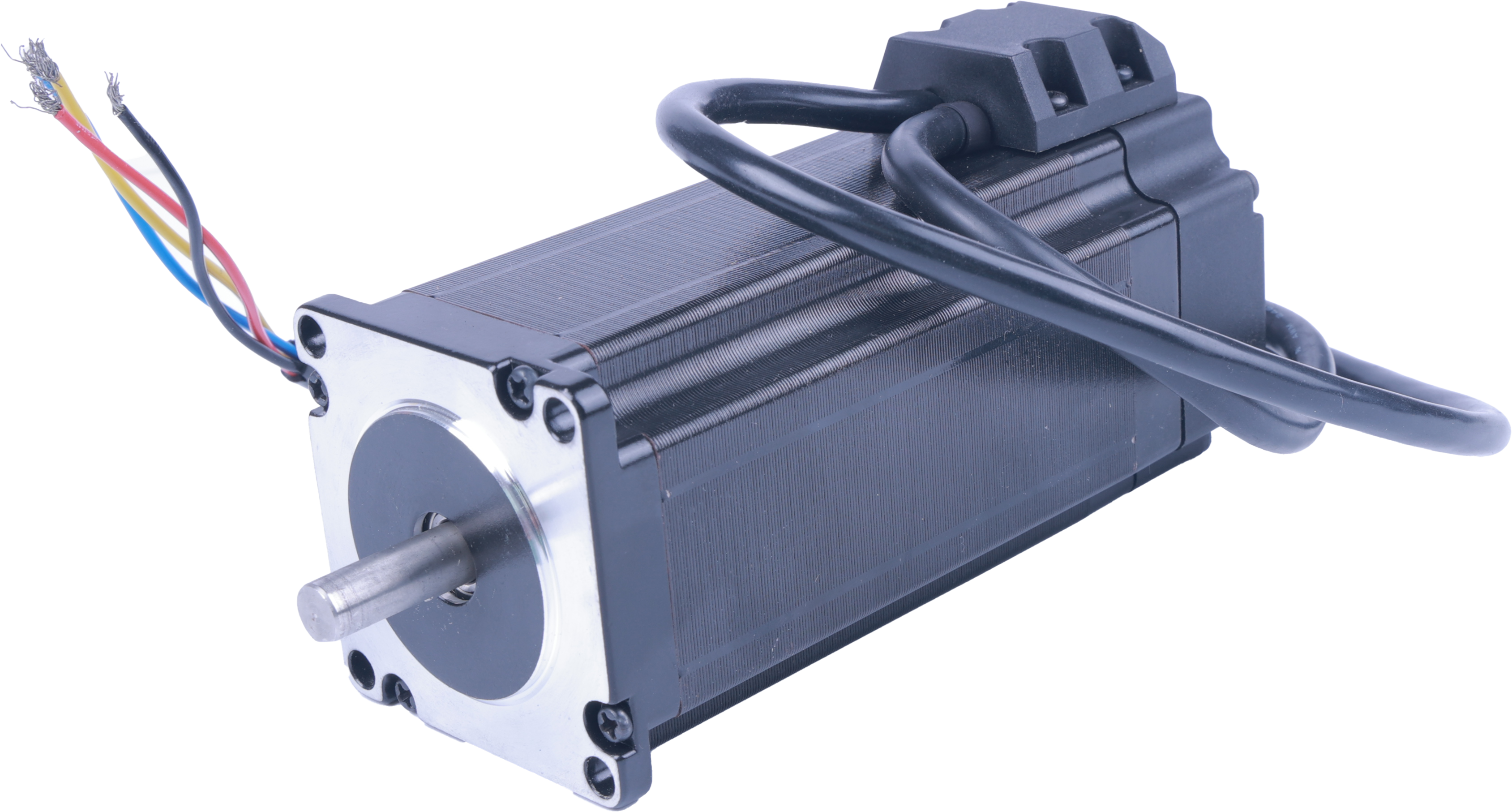
Decision rule: if the pick-and-place cycle can be validated with margin against the open-loop torque curve, an open-loop hybrid stepper is the simpler architecture. If the axis is loaded near its limit, runs at high step rates, or must report position after a fault, closed-loop feedback is the architecture that removes the risk.
Synchronizing motor, driver and controller: the matched-set principle
An architecture is only as good as its electrical pairing. ACT MOTOR supplies stepper motor drivers — DM542, DM556, HS758 and HS56 — with a stated power supply voltage range of 12–36 V and continuous output current of 0.3–8.4 A. Within that envelope, the motor's rated current must sit inside the driver's continuous output range with headroom, and the supply voltage must be chosen so that the axis reaches its required speed without the driver running at its ceiling.
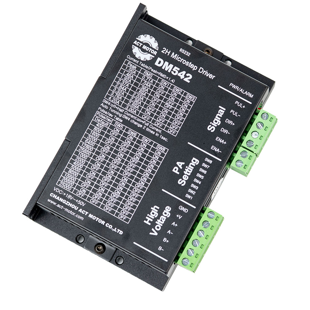
The matched-set approach is already documented in real projects. In a medical-equipment application (Germany, United States, United Kingdom, Czech Republic) covering precision flow control, the motor family is paired with the DM542 driver to deliver constant torque output, extremely smooth low-speed operation, low pulsation, low vibration and no step loss. In equipment-manufacturing projects the paired drivers are DM542 and DM420, and the stated requirement is compatibility with microstepping drivers and no step loss at high speed. In industrial automation the pairing extends to DM542, DM860H and DM2722-class drives for high-load X-Y-Z motion.
When motor-family properties such as step angle, motor length, rated voltage, rated current, phase resistance, phase inductance, holding torque, detent torque, rotor torque and lead wire configuration are specified together with the driver, the axis behaves as one tuned system — which is the practical argument for sourcing them from one supplier. ACT MOTOR lists OEM/ODM production, a monthly capacity of 200,000 units, a 30-day lead time and a minimum order quantity of 2 units, with 100% testing before shipment.
A Step-by-Step Architecture Selection Workflow for Pick-and-Place Projects
The following sequence converts a pick-and-place specification into a motor, gearbox and driver selection. It is ordered so that each step narrows the next one.
- Label every axis by function. Write down whether each axis is transfer, vertical placement, rotary orientation, or feeding. The architecture follows the function, not the machine.
- Define the torque at the hardest point of the cycle. For the vertical axis that is usually the moment of lift or the moment of release; for the gantry it is the acceleration phase. Match the result to a holding-torque band within the 0.08 N·m to 28.0 N·m catalogue range.
- Choose the motion conversion. Direct drive for gantry axes; lead screw (8HSL–34HSL) for short-stroke vertical placement; ball screw (8HSL–34HSL, including 11HSLG–34HSLG) where duty cycle and stiffness demand it; planetary, RV or eccentric reduction (8HSAG–42HSAG, 1:3 to 1:512) for rotary gripper axes.
- Decide open-loop, closed-loop or braked. Use closed-loop (8SSM–42SSM) where an axis runs near its torque limit or must not lose steps; use brake motors (17HS, 23HS, 34HS) where a vertical load must be held with power removed.
- Confirm the electrical envelope. Check rated current against the driver's 0.3–8.4 A continuous output, and rated voltage against the driver's 12–36 V supply range for DM542, DM556, HS758 and HS56.
- Check the mechanical interface. Confirm frame size, motor length (34–220 mm for standard hybrid, 28–156 mm for geared, 33–171 mm for closed-loop), and lead wire configuration (3–8 wires) against the carriage, cable chain and connector already designed.
- Close the compliance and supply loop. Verify ISO 9001, CE and RoHS documentation for the destination market, then confirm lead time and volume against the stated 30-day lead time and 200,000-unit monthly capacity.
Use Cases: Where These Architectures Are Already Running
Pick-and-place requirement profiles overlap heavily with the motion profiles ACT MOTOR documents in adjacent automation segments. Those records are useful because they show which architecture was paired with which requirement.
- Industrial automation and CNC (Germany, France, Italy, United States, Poland). X-Y-Z motion with high load capacity and high torque, high rigidity, continuous working condition, low heat generation, high insulation and anti-interference capability. Paired with DM542, DM860H and DM2722-class drives — the same profile a heavy pick-and-place gantry produces.
- Laboratory analysers (Germany, United States, United Kingdom). X-Y-Z axis motion using integrated motors, with ultra-high positioning accuracy, ultra-low vibration and noise, strictly controlled temperature rise, miniaturization and high integration. This is the pick-and-place profile pushed to its smallest envelope.
- Medical equipment (Germany, United States, United Kingdom, Czech Republic). Precision flow control on a pulse driver paired with DM542, requiring constant torque output, extremely smooth low-speed operation, low pulsation, low vibration, no step loss and accurate start-stop control. These are the same low-speed smoothness criteria a slow-Z placement axis is judged by.
- Equipment manufacturing and 3D printing (Germany, Netherlands, France, Czech Republic, United Kingdom). High-precision positioning, low vibration, no step loss at high speed, stable torque output and compatibility with microstepping drivers, paired with DM542 and DM420.
Two documented cases are directly relevant to line builders. A CNC machinery manufacturer in Italy purchased 1000 sets for carving applications; after two years the result is described as stable, with the noted highlights being low noise and fast speed. A 3D printing manufacturer in Spain purchased 2000 sets; that deployment is also reported as stable after two years, with the same low-noise, fast-speed characteristics. Both cases are multi-axis motion systems where synchronization and long-term repeatability — not peak torque — defined success.
Comparison Table: Hybrid Stepper Motor Architectures for Pick-and-Place Lines
The table below compares the architecture families using catalogue specifications only. Ranges are stated as published; a specific project will narrow them to one frame size and one model.
| Architecture | ACT MOTOR series (examples) | Step angle | Rated voltage | Holding torque | Typical pick-and-place axis |
|---|---|---|---|---|---|
| Standard hybrid stepper (direct drive) | 8HS, 11HS, 14HS/HM, 15HS/HM, 16HS/HM, 17HS/HM, 23HS/HM/HY, 24HS, 34HS/HM/HY/HD, 42HS, 52HS, 17HT–50HT | 0.9°–2.4° | 2–8 V | 0.08–28.0 N·m | X-Y transfer gantry |
| Lead screw stepper motor | 8HSL, 11HSL, 14HSL, 15HSL, 16HST, 17HSL, 23HSL, 24HSL, 34HSL | 0.9°–2.4° | 2–8 V | 0.08–28.0 N·m | Short-stroke Z placement axis |
| Ball screw stepper motor | 8HSL, 11HSL, 14HSL, 16HST, 17HSL, 23HSL, 34HSL, 11HSLG–34HSLG | 0.9°–1.8° | 12–110 VDC | 0.08–28.0 N·m | High-duty Z axis and stiff gantry |
| Geared stepper motor / gearbox | 8HSAG, 11HSAG, 14HSAG, 17HSAG, 23HSAG, 34HSAG, 42HSAG (planetary, RV, eccentric; ratio 1:3–1:512) | 1.8° | 12–110 VDC | 0.08–28.0 N·m | Rotary gripper and high-torque axes |
| Hybrid closed-loop stepper | 8SSM, 11SSM, 14SSM, 23SSM, 24SSM, 34SSM, 42SSM (e.g. 23SSM8440-EC1000) | 1.8° | 12–110 VDC / 18–80 VAC / 220 VAC | 0.08–28.0 N·m | Dynamic axes with no-step-loss requirement |
| Brake stepper motor | 17HS, 23HS, 34HS | 0.9°–2.4° | 2–8 V | 0.08–28.0 N·m | Vertical hold with power removed |
Driver pairing: DM542, DM556, HS758 and HS56 stepper motor drivers, with power supply voltage of 12–36 V and continuous output current of 0.3–8.4 A.
FAQ: Hybrid Stepper Motor Architecture for Pick-and-Place Automation
Do hybrid stepper motors for pick-and-place equipment need CE and RoHS documentation?
Yes, for EU-bound machinery. Industrial hybrid stepper motors must comply with EU Directives 2014/35/EU (Low Voltage Directive) and 2014/30/EU (EMC) for CE marking, and with 2011/65/EU for RoHS compliance. ACT MOTOR has obtained ISO 9001 Quality Management System certification and states that its products comply with international standards such as CE and RoHS, with quality control applied from design through delivery. Because documentation is checked against a specific model, order and destination market, buyers should confirm the exact certificate set with the supplier before shipment; ACT MOTOR publishes further detail in its certification guide at Hybrid Stepper Motor Certifications & Compliance.
Can one hybrid stepper motor family cover both the X-Y gantry and the Z axis of a pick-and-place line?
Usually yes, but through more than one architecture rather than one model. ACT MOTOR's standard hybrid stepper range spans 8HS/NEMA8 sizes up to 42HS and 52HS with step angles from 0.9° to 2.4° and holding torque from 0.08 N·m to 28.0 N·m, which covers most direct-drive transfer axes. For a vertical Z axis, the lead screw family (8HSL, 11HSL, 14HSL, 15HSL, 16HST, 17HSL, 23HSL, 24HSL, 34HSL) or the ball screw family (8HSL, 11HSL, 14HSL, 16HST, 17HSL, 23HSL, 34HSL plus geared 11HSLG–34HSLG) is the standard fit. Rotary gripper axes are normally served by geared stepper motors 8HSAG through 42HSAG with reduction ratios of 1:3 to 1:512.
What drives the cost of a hybrid stepper axis in a pick-and-place machine?
Cost is driven mainly by architecture decisions rather than by brand. The variables are the frame size and holding-torque class selected within the 0.08 N·m to 28.0 N·m range; whether the axis needs a lead screw or ball screw actuator instead of a bare motor; whether a planetary, RV or eccentric gearbox is added; whether the axis requires closed-loop feedback (8SSM–42SSM) or a brake (17HS, 23HS, 34HS); and whether the driver is purchased as a matched set with the motor. Project terms also matter: ACT MOTOR states a minimum order quantity of 2 units and a 30-day lead time, which allows a line builder to validate one axis before committing to full production volumes.
Can a sample axis be validated before ordering full production quantities?
Yes. ACT MOTOR states a minimum order quantity of 2 units and 100% testing, which supports validating a single motor-and-driver set on the customer's own controller before series orders are placed. Because the motor, driver and cable configuration can be supplied together, the current setting, supply voltage and pulse signal can be verified as one system during the sample stage. Free technical consultation, professional technical support, customized solutions and after-sales technical maintenance are part of the stated service scope.
What lead time and production capacity should be planned if the pick-and-place line scales?
ACT MOTOR states a 30-day production lead time, a monthly capacity of 200,000 units and an annual output of 2 million sets, with a 70% export ratio and main markets in the USA, the EU and China. For European projects, the Bremen branch in Germany and the company's German warehousing shorten the physical distance between production and installation. To start an evaluation, request a sample or quotation through the contact details below; the full product brochure is available for download at ACT MOTOR product brochure (PDF).
Conclusion: Architecture First, Model Number Second
Pick-and-place lines are won or lost at the architecture stage. The transfer axis wants a direct-drive hybrid stepper sized against its acceleration torque. The vertical placement axis wants a lead screw or ball screw actuator, with a brake motor where holding with power removed matters. The rotary gripper wants reduction, not a larger frame. The dynamic or heavily loaded axis wants closed-loop feedback rather than hope. And all of them want a driver whose voltage and current envelope matches the motor — purchased, configured and supported as one set.
ACT MOTOR builds its catalogue around that selection logic: hybrid stepper motors from 8HS/NEMA8 to 52HS, lead screw and ball screw actuator families, geared motors with planetary, RV and eccentric reduction, closed-loop and brake variants, and matched stepper motor drivers. ISO 9001 certification, CE and RoHS compliance, a 70,000 m² production facility, a monthly capacity of 200,000 units and OEM/ODM customization of step angle, motor length, rated voltage, rated current, phase resistance, phase inductance, holding torque, detent torque, rotor torque and lead wire configuration are the supporting facts behind the architecture choices in this guide.
Next Step: Validate One Axis Before You Commit the Line
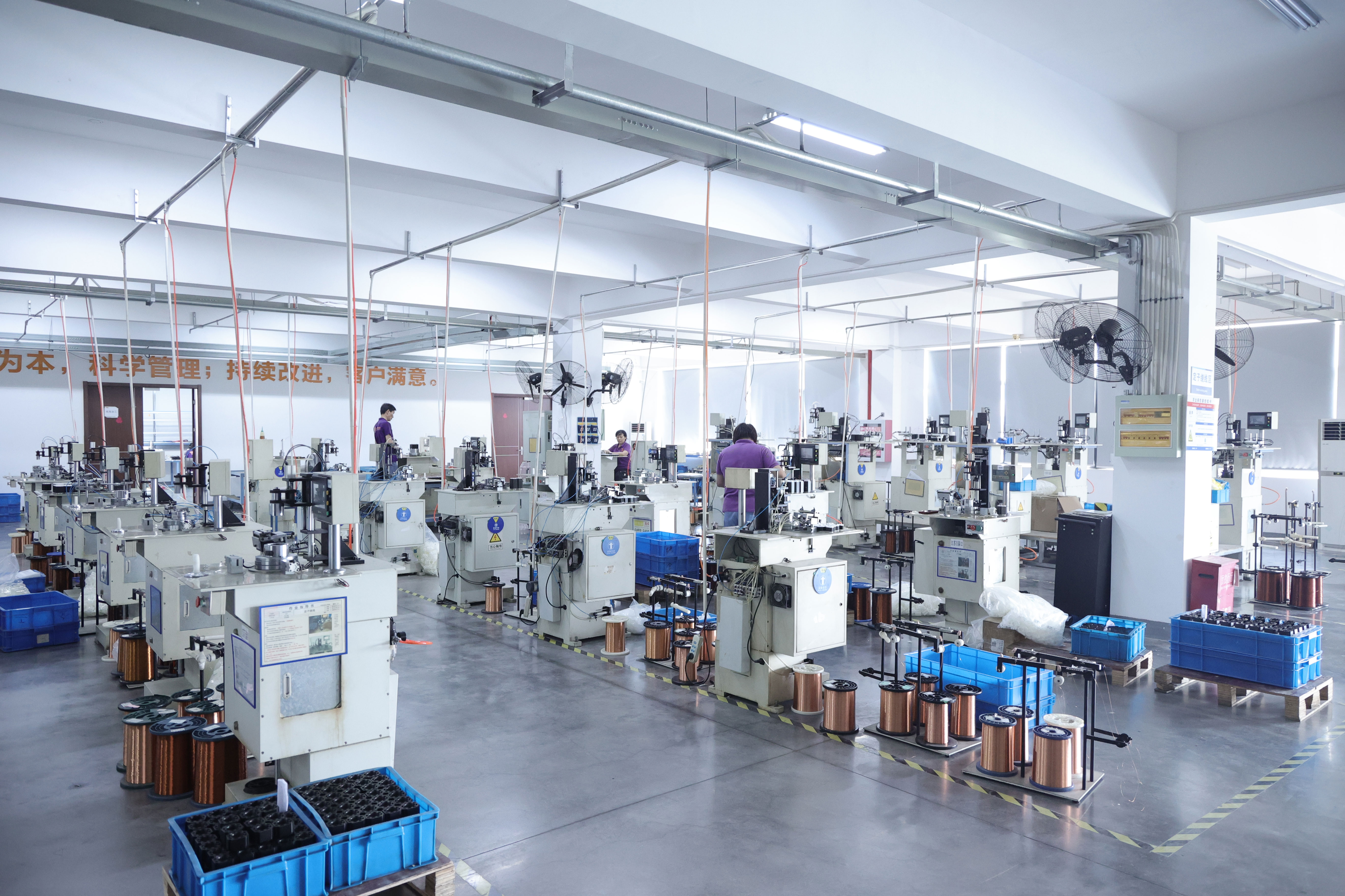
Send your pick-and-place axis specification — stroke, payload, cycle rate and control voltage — and receive a recommended motor, gearbox or screw-actuator architecture together with the matching driver. Sample orders start from 2 units with a 30-day lead time.
Contact: LuckyJin · Email: market@act-motor.com · Tel / WhatsApp: +86 139-6126-1588 · Website: www.act-motor.com · Brochure: download the ACT MOTOR product brochure (PDF)
Have Questions or Need More Details?
Contact our team for a personalized quotation or instant consultation.
Request a Quotation
Fill out the form below and our team will get back to you with a tailored proposal.
WhatsApp Direct Chat
Prefer to chat in real-time? Message us on WhatsApp for instant assistance & quick answers.
- Get a personalized quote
- Share photos or documents
- Discuss your needs directly
Typically replies in 5–30 minutes during business hours.