
Missed Steps, Stalls, and Vibration: A Troubleshooting Guide for Hybrid Stepper Motor Systems
Troubleshooting guide · Hybrid stepper systems
An axis that loses position in the middle of a cycle, a motor that stalls the moment the load arrives, and a low-speed vibration that makes a healthy machine sound like a failing one are the three most common complaints in hybrid stepper motor service work. None of them identifies a failed motor on its own. In a hybrid stepper system the same symptom can originate in the driver current setting, the motor-to-driver pairing, the load and inertia match, or a mechanical resonance band, and the cheapest fix is usually found before any part is replaced.
This guide is written for the engineer or buyer who has already chosen a hybrid stepper approach and now has to make it run, or who is evaluating whether to repair, replace or re-specify an existing axis. It works symptom first: what each symptom looks like, which of the four diagnostic domains it points to, an ordered check sequence, and the decision rule for replacing or re-specifying a Hybrid Stepper Motor together with a matched Hybrid Stepper Motor Driver.
ACT MOTOR (Changzhou ACT Motor Co., Ltd.) is a manufacturer of hybrid stepper motors, stepper motor drivers and related motion components, founded in 2010 and based in Changzhou, Jiangsu, China. The company operates a 70,000 m² production site, exports roughly 70% of its output to the USA, the EU and China, and builds the 8HS to 50HT hybrid stepper motor range, the DM542, DM556, HS758 and HS56 driver series, the 8SSM closed-loop series, and geared, lead screw, ball screw and brake variants. Its published specifications and certificate records are used throughout this guide as a reference for what a complete, verifiable specification package looks like when a replacement part is being specified.
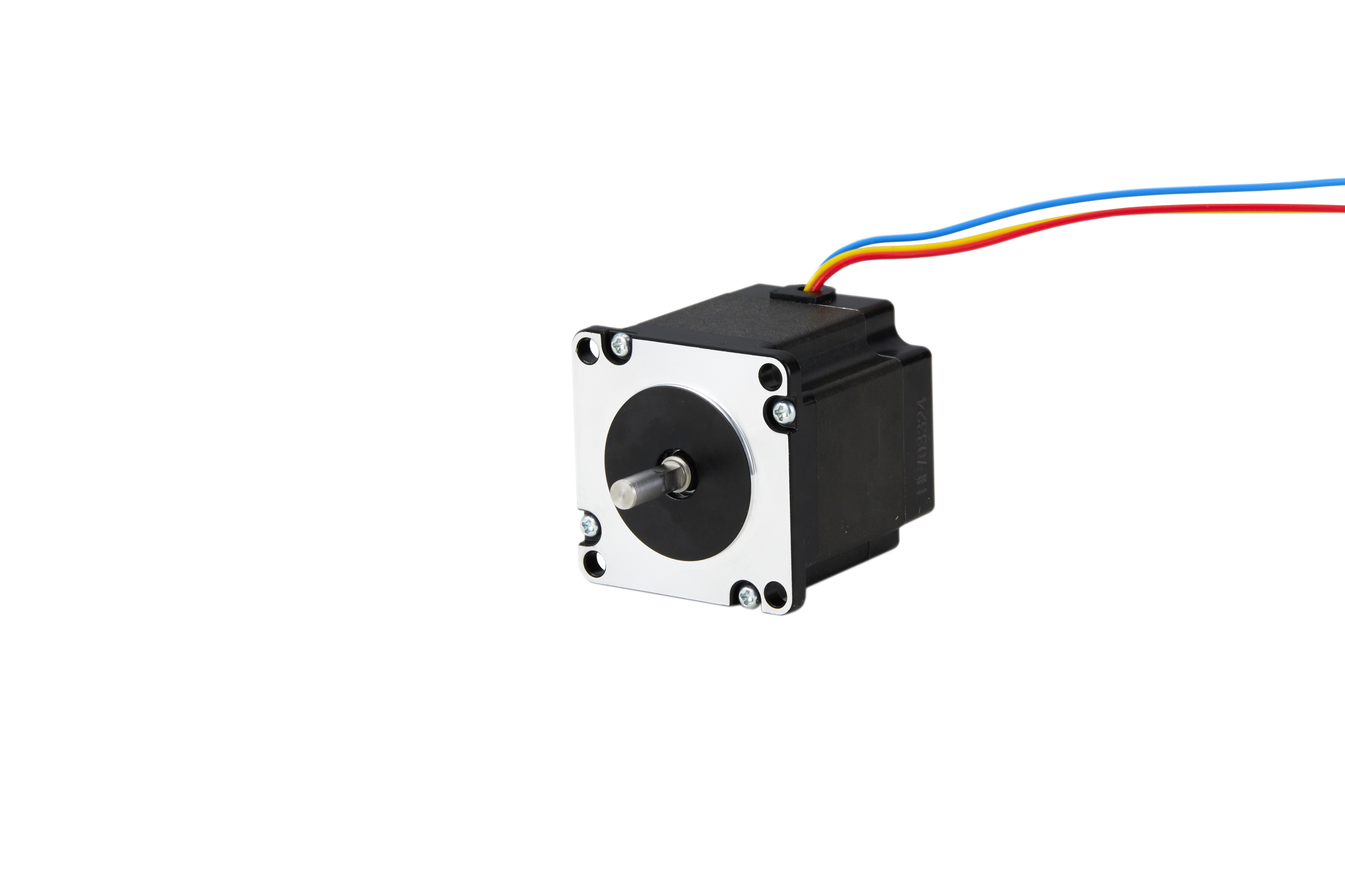
Hybrid stepper motor, 23HT series. Position loss, stalls and low-speed vibration are system-level symptoms, not automatic evidence of a failed motor. Image: ACT MOTOR.
Problem definition: what each symptom actually means
The three symptoms are often reported with the same words and treated as the same fault. They are not. Each one has a different signature, a different likely origin, and a different cost of correction.
Missed steps and cumulative position loss
A missed step is a commanded increment that the rotor did not complete. A standard hybrid stepper motor runs open-loop, so the controller has no way of knowing the increment was lost. The error surfaces later as a position offset, a skipped tool change, a part placed outside tolerance, or a machine that has to be re-homed between cycles. The diagnostic signature is repeatability: the error accumulates in one direction, tends to appear at the same point in the motion profile, and often appears during acceleration or during a direction reversal rather than at constant speed.
Stall under load
A stall is a complete loss of synchronism between the rotating field and the rotor. The motor stops or jumps to a new position, and in most machines the controller continues issuing pulses as if nothing happened. Stalls cluster around two moments: acceleration into a move, and the instant an external load arrives, such as a tool engaging material or a package landing on a conveyor. A stall that appears only under load is a torque question, not a positional one.
Low-speed vibration and mechanical resonance
Vibration is the only one of the three symptoms that usually leaves the axis working. Amplitude rises in a specific low-speed band, produces audible noise and visible shaft oscillation, and then falls away again above that band. Because the axis still performs at higher speeds, vibration is frequently tolerated until it damages a coupling, loosens a mount, or shows up as surface marks on the product.
Industry background: why this fault pattern is worth documenting
Hybrid stepper motors are not a niche component. Hybrid designs accounted for the largest share of the stepper motor market in 2025, at approximately 53.93% of total market value (KBV Research). The overall stepper motor market was valued at USD 3.962 billion in 2024 and is projected to reach USD 6.245 billion by 2035, growing at a CAGR of 4.22% (Market Research Future). Asia Pacific dominated the market in 2025 with a 48.91% share (Mordor Intelligence).
The application mix explains why missed steps, stalls and vibration matter commercially rather than only technically. Medical equipment is the fastest-growing application segment, with a projected CAGR of 7.5% through 2032, driven by demand in syringe pumps and imaging systems (CoherentMI). In metering and fluid handling, low-speed vibration is not a comfort issue; it appears as flow pulsation and dosing error. In packaging, logistics and CNC equipment, a stall is a production stop with a scrap cost attached. The high-torque segment alone was valued at USD 1.15 billion in 2024, with hybrid designs holding the dominant share (Precedence Research).
The supply side is consolidated around a group of established global suppliers, including MinebeaMitsumi, Sanyo Denki, Oriental Motor, Moons' Industries and Nidec Corporation (Market Research Future / Mordor Intelligence). Supplier comparison is a separate exercise from fault diagnosis. What matters here is that a replacement part must arrive with a specification and a compliance record specific enough to be checked against the installed system, because an undocumented substitution is how a resonance problem becomes a repeat failure.
Detailed solution: the four diagnostic domains
Domain 1 — Current setting and microstep configuration
Driver current is the first check because it is the fastest to change and the most common cause of load-dependent stalls. The hybrid stepper motor range from ACT MOTOR spans a rated current of 0.5 A to 8 A, phase resistance of 0.05 Ω to 10 Ω and phase inductance of 0.1 mH to 10 mH. The DM542, DM556, HS758 and HS56 driver series has a continuous output current of 0.3 A to 8.4 A and a supply voltage of 12 V to 36 V. Those two ranges have to overlap at the specific motor being driven, not merely at the top of the catalogue.
Setting the driver current too low produces exactly the reported symptom: the axis runs unloaded, then loses steps on acceleration or stalls when the load engages. Setting it too high produces the opposite problem. The motor runs hotter, and sustained heat reduces the torque margin that the higher current was meant to buy. The practical rule is to start below the motor rated current and raise it only until the axis completes its heaviest move reliably, then confirm the temperature rise over a full duty cycle.
Microstepping is frequently used as a remedy for vibration and rarely solves a torque problem. Finer microstepping smooths low-speed motion and reduces the amplitude of the step transitions, but it does not increase holding torque. If an axis stalls at the required load, increasing microstep resolution will not recover the lost torque; it may simply make the stall quieter.
Domain 2 — Driver pairing and wiring
Pairing failures are structural rather than adjustable. In a bipolar hybrid stepper motor the winding can be connected in series or in parallel depending on the lead configuration, and the standard range carries 3 to 8 lead wires. A motor wired in the wrong configuration can run, but it will run with reduced torque or with abnormal heating, and it will behave inconsistently across the speed range. The closed-loop 8SSM series uses 2 to 8 lead wires and a wider supply window of 12–110 VDC, 18–80 VAC or 220 VAC, which changes the pairing options.
A second pairing error is confusion between the motor rated voltage and the driver supply voltage. The standard hybrid stepper motor range is rated at 2 V to 8 V, while the driver supply is 12 V to 36 V. These are not competing numbers and are not a mismatch. The low figure describes the winding; the higher figure is the bus voltage used by the chopper stage. Reading the rated voltage as a required supply leads to under-driving the motor, which then presents as a stall that no amount of current adjustment will fix.
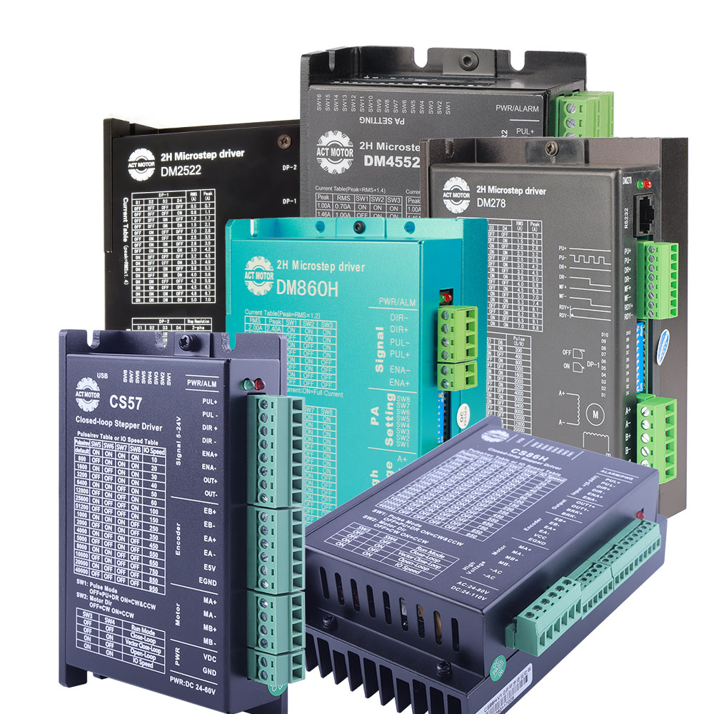
A matched motor and driver combination. Pairing must be checked at the winding level, not only at the nameplate level. Image: ACT MOTOR.
Signal-level faults belong to the same domain. Pulse width, direction setup time and enable logic all have to satisfy the driver input specification. A pulse that is too short for the opto-isolated input is interpreted intermittently, which produces random single-step losses that look like a mechanical fault and move around the machine.
Domain 3 — Load, torque and inertia match
Holding torque across the ACT MOTOR hybrid stepper motor range is 0.08 N·m to 28.0 N·m, with detent torque of 0.01 N·m to 0.75 N·m and rotor inertia of 0.004 kg·cm² to 10 kg·cm². Holding torque is a standstill figure. It is not the torque available during acceleration, and it is not the torque available at speed. A sizing exercise that compares a required running torque against a holding torque figure will produce an undersized axis that stalls only under real load.
Inertia matching matters in the opposite direction. An oversized motor brings high rotor inertia, and a large rotor driving a light load can oscillate and settle slowly even though it has torque to spare. When the load fundamentally needs more torque at low speed, gearing is the correct answer rather than a larger frame. Geared stepper motors in the ACT MOTOR range offer reduction ratios from 1:3 to 1:512 at a 1.8° step angle, which trades speed for torque in a predictable way, at the cost of backlash that has to be considered in bidirectional positioning.
For linear motion, the transmission choice changes the symptom. Ball screw stepper motors (0.9°–1.8° step angle, 12–110 VDC) run with lower friction and are more readily back-driven; lead screw stepper motors (0.9°–2.4° step angle) are typically self-locking and better at holding a vertical position. On a vertical axis, a brake stepper motor from the 17HS, 23HS or 34HS series is the correct answer when the position must be held with power removed.
Domain 4 — Mechanical resonance
Resonance is a property of the assembled system, not of the motor alone. The motor, coupling, screw, mount and moving mass form a resonant system, and the amplitude of the oscillation peaks inside a speed band and falls away outside it. The diagnostic signature is unambiguous: if the axis stalls or vibrates at one specific speed and runs cleanly at a higher and a lower speed, torque is not the limiting factor.
Practical countermeasures are mechanical and profile-based rather than electrical. Reducing microstep resolution or changing the current decay setting can move the system out of the problematic band. Adjusting the acceleration profile so the axis passes quickly through the band avoids continuous operation inside it. Coupling alignment, mount stiffness and added damping change the resonant frequency itself. Replacing the motor without changing any of these usually relocates the problem to a slightly different speed.
Step-by-step diagnostic sequence
The order below is deliberate. Each step is cheaper and more reversible than the one after it, and each step should end with a recorded observation rather than an impression.
- Record the symptom with its operating conditions. Note the speed at which the fault appears, the load on the axis, the direction of travel, whether the fault is repeatable at the same position, and the ambient and motor temperature. A fault that disappears when the machine is cold points to a different domain than a fault that appears only after an hour of running.
- Verify the electrical basics before adjusting anything. Confirm the supply voltage is inside the driver range of 12–36 V, confirm the lead configuration matches the motor winding, and confirm grounding and shielding on the pulse and direction lines. Most intermittent single-step losses are resolved here.
- Check the driver current against the motor rated current. Use the motor nameplate rating within the 0.5–8 A range and confirm the driver can deliver it within its 0.3–8.4 A continuous output. Record the setting before changing it so the change can be reversed.
- Confirm the pulse and direction timing from the controller. Verify pulse width, direction setup time and enable logic against the driver input specification. Random losses that move around the machine rather than repeating at one position usually belong to this step.
- Test the axis at low speed with a different microstep and decay setting. If the vibration disappears at a different resolution without any mechanical change, the fault is in the resonance domain, not the torque domain.
- Isolate the mechanics from the electrics. Disconnect the load or the coupling and run the motor alone. If the motor runs cleanly unloaded, the fault is downstream: screw friction, gearbox backlash, rail binding or a misaligned coupling.
- Run a thermal check over a full duty cycle. Measure or observe the motor and driver temperature after continuous operation. A motor that is hot enough to derate will show the same missed-step symptom as an under-current setting, and adjusting current upward makes it worse.
- Decide between adjustment, repair, replacement and re-specification. Use the decision table below rather than repeating the same adjustment a second time.
Decision table: adjust, repair, replace or re-specify
| Observation | Most likely domain | First action | Re-specify when |
|---|---|---|---|
| Stalls only during acceleration, runs at constant speed | Current setting or torque margin | Raise current toward the motor rating and re-test | The motor is already at its rated current and still stalls |
| Stalls only when the external load engages | Load and torque match | Re-calculate running torque, not holding torque | Required torque exceeds the frame size at the needed speed |
| Random single-step losses at different positions | Driver pairing or signal timing | Check wiring, lead configuration, pulse width, grounding | The controller and driver signal levels are incompatible |
| Vibration and noise in one narrow low-speed band | Mechanical resonance | Change microstep, decay and acceleration profile | The band cannot be avoided in the process cycle |
| Position error after a direction reversal | Mechanical backlash | Check coupling, gearbox and screw preload | Backlash is inherent to the transmission choice |
| Motor hot and losing steps after long running | Thermal derating | Reduce current or improve cooling | The duty cycle requires more thermal margin than the frame size provides |
Which configuration addresses which symptom
The comparison below uses only the published specifications for the ACT MOTOR hybrid stepper motor range. It is a diagnostic mapping, not a performance ranking: the correct configuration is the one that removes the symptom without adding cost or complexity elsewhere in the machine.
| Configuration | Step angle | Holding torque | Key electrical parameter | Symptom it typically addresses |
|---|---|---|---|---|
| Standard Hybrid Stepper Motor (8HS–50HT) | 0.9°–2.4° | 0.08–28.0 N·m | Rated 2–8 V, 0.5–8 A, 3–8 lead wires, motor length 34–220 mm | Baseline open-loop axis; correct starting point for any diagnosis |
| Closed-loop hybrid (8SSM–42SSM) | 1.8° | 0.08–28.0 N·m | 12–110 VDC / 18–80 VAC / 220 VAC, 2–8 lead wires, motor length 33–171 mm | Repeated missed steps with no mechanical cause found |
| Geared (8HSAG–42HSAG) | 1.8° | 0.08–28.0 N·m | Reduction ratio 1:3–1:512, 12–110 VDC, motor length 28–156 mm | Stall on a load that needs more torque at low speed |
| Lead screw (8HSL–34HSL) | 0.9°–2.4° | 0.08–28.0 N·m | Rated 2–8 V, 0.5–8 A, motor length 34–220 mm | Linear motion where a self-locking transmission is preferred |
| Ball screw (8HSL–34HSLG) | 0.9°–1.8° | 0.08–28.0 N·m | 12–110 VDC, 0.5–8 A, phase resistance 0.05–10 Ω | Precision linear motion with lower friction |
| Brake (17HS, 23HS, 34HS) | 0.9°–2.4° | 0.08–28.0 N·m | Rated 2–8 V, 0.5–8 A, 3–8 lead wires | Vertical axis that must hold position with power removed |
Driver pairing follows the same logic. The DM542, DM556, HS758 and HS56 series is specified at 12–36 V supply and 0.3–8.4 A continuous output. The driver must be able to deliver the motor rated current at the chosen setting, and it must accept the pulse and direction signals the controller produces. A driver that satisfies both conditions is the correct pairing even if a larger model is available.
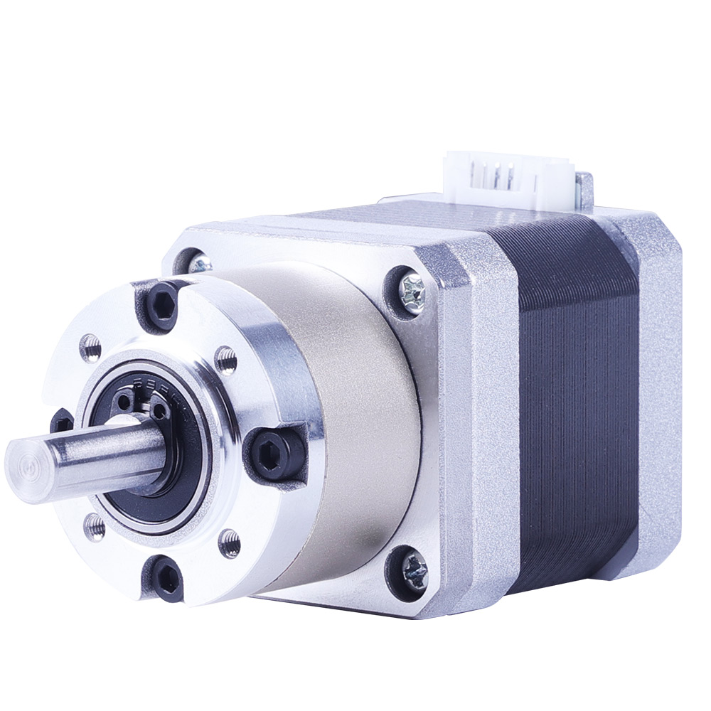
Geared hybrid stepper motor, 17HS4413AG5. When the load needs more torque at low speed, gearing is the structural fix rather than a larger frame. Image: ACT MOTOR.
Use cases: how the sequence plays out in real machines
Medical peristaltic pump — vibration as metering error
A peristaltic pump driven by a hybrid stepper motor paired with a DM542 driver is a low-speed application with an unusually strict smoothness requirement. The documented operating requirements for this application are constant torque output, extremely smooth low-speed operation, precise flow control, low pulsation, low vibration and low noise, together with accurate start-stop control without step loss over long continuous running. In this case vibration is not a maintenance complaint; it appears directly as flow pulsation. The diagnostic order therefore starts at microstep and decay settings and at the resonance band, and only then considers the torque margin.
Laboratory analyser — X/Y/Z positioning
Analytical instruments move an X/Y/Z stage with an integrated stepper motor and require ultra-high positioning accuracy, ultra-low vibration and noise, controlled temperature rise, and a compact, lightweight build. Here the thermal check in step 7 carries most of the diagnostic weight, because a motor that is merely warm in open air can exceed the allowable temperature rise inside an enclosed instrument.
CNC and industrial automation — continuous duty and load variation
Industrial automation axes using DM542, DM860H or DM2722 drivers require high load capacity, high rigidity, continuous operation with low heat generation, high insulation and reliable anti-interference behaviour. One CNC machinery manufacturer in Italy has run 1000 sets for two years with stable operation, citing low noise and fast speed as the operating characteristics that mattered in the application. In this duty pattern the first diagnostic question is usually whether a stall is a torque event during acceleration or a thermal event after several hours.
3D printing — step loss at speed
3D printer axes driven through DM542 or DM420 drivers require high-precision positioning, low vibration, no step loss at high speed, stable extrusion torque and compatibility with microstepping drivers, with different priorities on the X, Y, Z and extruder axes. A 3D printing manufacturer in Spain has run 2000 sets for two years, again with low noise and fast speed as the reported characteristics. In this application a missed step is often a pulse-timing problem rather than a torque problem, which places step 4 ahead of step 3 in the sequence.
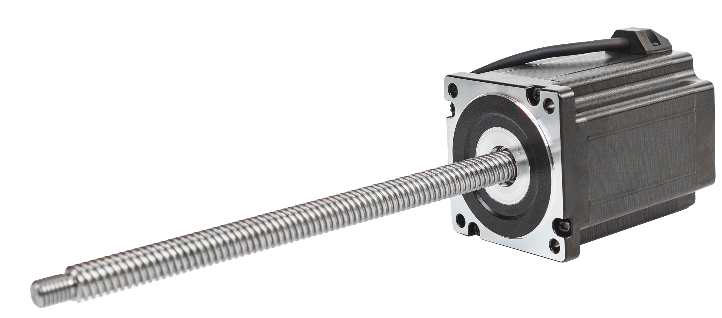
Ball screw hybrid stepper motor, 34HSL. The transmission choice changes which symptom appears first on a linear axis. Image: ACT MOTOR.
When replacing or re-specifying is the right decision
Replacement is justified when the diagnostic sequence has been completed and one of four conditions holds. First, the motor is at its rated current and still stalls on the heaviest move, which means the frame size is below the load requirement. Second, repeated missed steps persist after wiring, signal timing and mechanics have been verified, which is the case where a closed-loop 8SSM motor provides feedback the open-loop system cannot. Third, the required torque at the required speed cannot be reached within the current frame and supply, which is a gearing or transmission decision rather than a motor decision. Fourth, the duty cycle keeps the motor at a temperature where it derates, which is a thermal margin problem that no setting change will remove.
Re-specification differs from replacement in one important respect: the motor and the driver are specified together. A new motor on an unchanged driver repeats the original pairing error, and a new driver on an unchanged motor repeats the original current-setting error. The pairing to confirm is the motor rated current against the driver continuous output, the motor winding against the lead configuration, and the motor rated voltage against the driver supply as two separate quantities with two separate meanings.
Compliance records that support a documented replacement
For machinery exported to the EU, hybrid stepper motors and their drivers fall under the Low Voltage Directive 2014/35/EU and the EMC Directive 2014/30/EU for CE marking, and under the RoHS Directive 2011/65/EU for restricted substances (International Trade Compliance Association / ACT MOTOR compliance guide). The certificate records below are the ones ACT MOTOR maintains for this product family, and they illustrate the level of documentation a buyer should expect when a replacement part is specified.
| Record | Reference | Issued by | Valid until | Scope |
|---|---|---|---|---|
| CE — motor | ISETC.000520211115 | ISET | 2026-11-14 | EN 60034-1:2010/AC:2010, EN 61000-6-1:2019, EN 61000-6-3:2007+A1:2011+AC:2012, EN 61000-3-2:2019, EN 61000-3-3:2013+A1:2019 |
| CE — driver | ISETC.000320211115 | ISET | 2026-11-14 | EN 61800-3:2004/A1:2012, EN 61800-5-1:2007+A1:2017 |
| CE — power supply | ISETC.000420211115 | ISET | 2026-11-14 | EN 61558-1:2005/A1:2009, EN 61558-2-16:2009/A1:2013, EN 61000-6-1:2019, EN 61000-6-3:2007+A1:2011+AC:2012 |
| ISO 9001 quality management system | 07625Q2378R1S-JS/001 | ZRX | 2028-10-12 | GB/T19001-2016 / ISO 9001:2015, issued 2025-10-13 |
| RoHS test report — motor | GTS2408190853EN | GTS | 2029-08-29 | IEC 62321 series, issued 2024-08-30 |
| RoHS test report — driver | GTS2408190852EN | GTS | 2029-08-29 | IEC 62321 series, issued 2024-08-30 |

CE certificate for the driver family, covering the LVD and EMC standards listed above. Image: ACT MOTOR.
Frequently asked questions
Which compliance documents should accompany a replacement hybrid stepper motor and driver?
A replacement for an EU-bound machine should come with CE documentation covering the Low Voltage Directive 2014/35/EU and the EMC Directive 2014/30/EU, RoHS evidence under Directive 2011/65/EU, and a current ISO 9001 certificate for the manufacturer. For the ACT MOTOR hybrid stepper motor family these are CE certificate ISETC.000520211115 for motors, ISETC.000320211115 for drivers and ISETC.000420211115 for power supplies, all issued by ISET and valid until 2026-11-14; RoHS test reports GTS2408190853EN for motors and GTS2408190852EN for drivers, issued by GTS and valid until 2029-08-29; and ISO 9001 certificate 07625Q2378R1S-JS/001 issued by ZRX, valid from 2025-10-13 to 2028-10-12. Documents should be checked against the exact model being supplied, not only against the brand.
Can a hybrid stepper motor be customised to match an existing machine specification?
Yes, within a defined parameter set. ACT MOTOR operates in OEM and ODM mode and lists the customisable parameters as step angle, motor length, rated voltage, rated current, phase resistance, phase inductance, holding torque, detent torque, rotor torque and lead-wire count. Production capacity is 200,000 units per month with 100% testing, and the minimum order quantity is 2 units. For a replacement project the parameters to confirm first are the step angle, the holding torque band and the lead-wire configuration, because those three determine whether the existing driver can be reused.
How should two hybrid stepper motor quotations be compared on budget?
Compare the configured specification rather than a headline unit price. The relevant variables are the holding torque band within the 0.08–28.0 N·m range, the step angle within 0.9°–2.4°, the lead-wire count within 3–8, whether a gearbox is included and at what reduction ratio within 1:3–1:512, whether a brake or closed-loop 8SSM configuration is required, and whether a matched driver from the DM542, DM556, HS758 or HS56 series is quoted with the motor. A quotation that omits the driver or the compliance documents is not comparable, because both are part of a functioning replacement rather than optional extras.
Can a sample be supplied before a production order?
Yes. The minimum order quantity for ACT MOTOR hybrid stepper motors is 2 units, which allows a sample to be evaluated on the machine before a production commitment. A useful sample validation covers four checks: run the axis at the lowest production speed to look for the resonance band, run the heaviest move at the acceleration used in production to confirm the torque margin, run a full duty cycle to observe temperature rise, and verify the lead configuration and connector against the existing harness.
What is the lead time for a hybrid stepper motor and matched driver order?
The quoted production lead time is 30 days, supported by a monthly capacity of 200,000 units across a 70,000 m² production site in Changzhou, Jiangsu, China. European customers are served through the company branch in Bremen, Germany, alongside offices in Shanghai and Jinan. For a replacement or re-specification project, the fastest route is to send the existing motor model, the fault description from the diagnostic sequence above, and the required holding torque and step angle, so that the motor and the driver can be quoted as a matched pair. Technical enquiries can be sent to market@act-motor.com or raised by phone and WhatsApp on +86 139-6126-1588.
Conclusion: diagnose the system, then specify the pair
Missed steps, stalls and low-speed vibration are three different faults with three different signatures, and they resolve through one ordered sequence: current setting, driver pairing, load and inertia match, then mechanical resonance. Working in that order keeps the cheap and reversible checks ahead of the expensive ones, and it produces a record of what was tested rather than a list of parts that were swapped.
Replacement becomes the correct decision at a specific point, not at the first failed adjustment. That point is reached when the motor is at its rated current and still stalls, when missed steps persist after wiring and signal timing are verified, when the required torque exceeds what the frame can deliver at the required speed, or when the duty cycle keeps the motor in thermal derating. At that point the motor and the driver should be re-specified together, against a documented specification and a current compliance record, because a correctly paired system is what prevents the same symptom from returning under a new part number.

Hybrid stepper motor and driver production at ACT MOTOR, Changzhou, Jiangsu, China. Image: ACT MOTOR.
Need a matched motor and driver for a failing axis?
Send the existing motor model, the symptom and the operating conditions, and ACT MOTOR will confirm the holding torque, step angle, lead configuration and driver pairing against the documented range. Samples start from 2 units, and the quoted production lead time is 30 days.
Email: market@act-motor.com | Tel / WhatsApp: +86 139-6126-1588 | Website: www.act-motor.com
Address: No.18, Boyang Road, Jintan Area, Changzhou, Jiangsu, China
Download the full product catalogue: ACT MOTOR product brochure (PDF)
Have Questions or Need More Details?
Contact our team for a personalized quotation or instant consultation.
Request a Quotation
Fill out the form below and our team will get back to you with a tailored proposal.
WhatsApp Direct Chat
Prefer to chat in real-time? Message us on WhatsApp for instant assistance & quick answers.
- Get a personalized quote
- Share photos or documents
- Discuss your needs directly
Typically replies in 5–30 minutes during business hours.