
2+2 Power-Signal DC Connector: Current, IP and Mating Specs
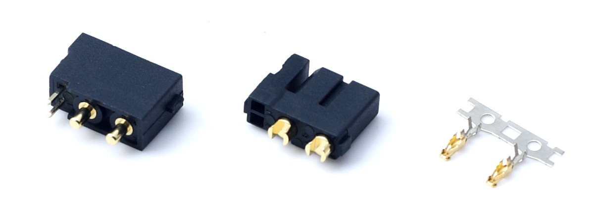
A 2+2 combo connector in its mated pair format: two heavy power contacts and two low-current signal contacts share a single housing and a single locking interface.
A 2+2 power-signal high-current DC connector places two heavy power contacts and two low-current signal contacts inside one shell. One mating action then carries the battery current and the control lines that supervise it: BMS communication, pack identification, temperature sensing or an enable loop. That integration is why the format shows up in lithium battery packs, UAV and RC power harnesses, service robots, garden tools, electric two-wheelers and small energy-storage equipment.
This guide is written for teams that have already chosen a combo connector architecture and now have to release a drawing, a specification and a purchase order. It walks through each parameter in the order that failures usually appear in the field: current, voltage and temperature, ingress protection, contact resistance and plating, anti-spark behaviour, then mating, locking and vibration. The last sections turn those parameters into a specification sequence, a verification checklist and a worked example using the DXT30U(2+2)-F(B).
How to read the values in this guide. The -20 °C to +120 °C operating window, the IP40 standard versus IP67 waterproof choice, and the 1000 mating cycle target are treated here as specification targets to be confirmed against a specific model's datasheet and test report. They are not published measurements for any single part number. Where a supporting document exists, this guide names it so you can request the exact record rather than accept a catalogue headline.
What "2+2" Means in a Connector Pin Layout
The 2+2 label describes the contact count and how it is split. Two power contacts are sized for the pack current and are arranged as a positive and negative pair. Two signal contacts are intended for low-current circuits such as BMS data lines, a pack ID resistor, a thermistor loop or an enable/shunt-trip line. Power and signal sit in the same insulator body and are keyed so the assembly can only be mated one way.
Three layout decisions deserve attention before you approve a drawing. First, contact spacing: the gap between a power contact and an adjacent signal contact is a creepage and clearance question, not a cosmetic one, especially when the pack voltage is well above the signal level. Second, keying and polarity: a shell that can be forced into the wrong orientation will eventually be forced into the wrong orientation during field service. Third, mate sequencing: some designs intend one signal contact to engage before the power contacts, which can be used for a pre-charge path or a ground reference. If sequencing matters, it must be written into the drawing, because a generic 2+2 layout will not provide it automatically.
Signal contacts in this format are low-current by design. If you intend to route a pre-charge current through a signal contact, verify that the contact is rated for that current for the required duration; a signal contact sized for milliamps is not a pre-charge contact.
The Problem: Two Electrical Domains Sharing One Shell
A combo connector has to satisfy two very different sets of requirements at once. The power side cares about milliohms of contact resistance, heat at continuous load, and the arc that appears when a live pack meets a capacitive load. The signal side cares about a stable, low-noise connection where a few tens of milliohms of drift can look like a fault to the BMS.
When a 2+2 connector is specified loosely, the same failure patterns recur:
- Intermittent signal dropout that the control board reports as a BMS or communication fault, traced back to a signal contact that was never checked against vibration or mating cycles.
- Local heating at the power contacts when a headline current rating is applied without the ambient, conductor and counterpart conditions it was measured under.
- Water ingress where an IP40 interface was used outside a sealed enclosure, or where an IP67 pair was mated with a damaged seal.
- Pitting or welded contacts after repeated hot-plug connection into a large input capacitance without any pre-charge strategy.
At the Evaluation-to-Execution stage the architecture is usually fixed. What remains open is the exact parameter set and the document that proves each value. That is the gap this guide closes.
Industry Background: Where 2+2 Connectors Sit
High-current connection is a large and still specialised category. Fact.MR estimated the global high power connectors market at approximately USD 5.47 billion in 2025, while Dataintelo reported that DC connectors represented 58.7% of the energy storage connector market in 2025, driven by higher voltage requirements. Both figures are commercial research estimates with their own product scope, and they describe the category rather than any individual supplier.
At the component level, XT60 and XT90 remain the reference formats for medium and high power non-proprietary RC aircraft and drone battery-to-ESC connections in 2026, according to ChinaHobbyLine's connector compatibility guide. A 2+2 combo connector is not a replacement for that base format; it is an application-specific layer used when power and signal must be mated in one action, or when a harness must be made mistake-proof.

Two-contact high-current pairs remain the base of most UAV and RC harnesses; a 2+2 combo adds the signal pair to the same mating action.
Current: Continuous Rating Versus Peak Rating
A current rating only means something when it is attached to conditions. The continuous rating is the current a mated pair can carry indefinitely while staying inside a stated temperature-rise limit, at a stated ambient temperature, with a stated conductor size, mated to a stated counterpart. The peak rating is a short-duration value that must also state duration and duty cycle. A single "max amps" number with no conditions is not a specification you can design to.
The two ratings matter differently by application. In a spraying UAV or an RC model, the continuous figure governs cruise and hover while the peak figure covers take-off and aggressive manoeuvres, so both must be checked against the flight profile. In a portable energy-storage unit or a service robot, the load is closer to steady state, which makes the continuous rating and its ambient basis the deciding number. In a two-wheeler or battery exchange cabinet, the connector sees repeated high-current bursts plus a thermal soak between uses.
What to ask for, in writing:
- The ambient temperature at which the continuous rating applies.
- The conductor cross-section used in the test.
- The mating counterpart, because the pair is what carries the current.
- The permitted temperature rise and how it was measured.
- A derating curve, so you can see what happens above the reference ambient.
Electrical performance of this kind is normally evidenced by a test report to the IEC 60512 series or GB/T 5095, issued by a third-party laboratory with CNAS, CMA and ISO 17025 accreditation. That report is the document that turns a datasheet number into a verifiable claim.
Voltage and the -20 °C to +120 °C Temperature Window
Rated voltage is not the same as system voltage. The rated voltage of a connector describes the insulation capability of the mated assembly, and it must clear your pack's maximum voltage with margin for transients. For EU-bound equipment, a CE-LVD declaration of conformity to Directive 2014/35/EU, assessed against EN 61984 for connectors, is the document that supports the safety claim; it is a manufacturer self-declaration issued with an EU authorised representative, not a third-party certificate.
Temperature is where current and material meet. The -20 °C to +120 °C window used in this guide is a working envelope for lithium battery, UAV and energy-storage hardware, and it should be read as the range the mated assembly must survive, not as a single contact temperature. Contact temperature rise adds to ambient: a connector running a 40 °C rise in a 60 °C enclosure is already at 100 °C at the contact. Ask whether the published range applies to the insulator, the contact, or the mated assembly, and confirm the range in the model datasheet.
Housing material carries the high-temperature end of that envelope. A UL94 V-0 flammability test report to the UL 94 standard is the verification document to request. For the DXT30U(2+2)-F(B) family, the housing is described by the manufacturer as a flame-retardant engineering plastic with a UL94 V-0 report on file; the practical question for a buyer is whether the report covers the exact material grade used in the parts you receive, which the report itself will show.
IP40 or IP67: Let the Enclosure Decide
Ingress protection follows the enclosure, not the catalogue page. In the two-digit IP code, the first digit covers solids and the second covers liquids: IP40 means protection against solid objects larger than 1 mm with no liquid protection, while IP67 means a dust-tight housing protected against temporary immersion. Both ratings apply to the mated pair in its stated condition. A connector rated IP67 does not make an unsealed cable gland waterproof, and an IP40 connector inside a sealed enclosure does not need to be.
| Attribute | IP40 standard | IP67 waterproof option |
|---|---|---|
| Solid protection | Objects larger than 1 mm; not dust-tight | Dust-tight |
| Liquid protection | None | Temporary immersion |
| Suitable placement | Inside a sealed battery box, robot chassis or control cabinet | Exposed mated interface: outdoor UAV, garden tool, street-light module, washdown area |
| Extra burden on the design | Enclosure sealing and strain relief must be handled elsewhere | Seal integrity at every mating cycle; mating discipline in field service |
| Corrosion evidence to request | Not usually critical indoors | Salt spray test report to ASTM B117 or GB/T 10125 |
The decision rule is simple. If the mated interface stays inside a sealed enclosure for its whole service life, IP40 is the lower-cost, lower-maintenance choice. If the interface is exposed to rain, condensation, washdown or dust, use a waterproof pair. The AOYG range includes a waterproof pairing, DXT60EW-M with DXT60W-F, for exposed interfaces; confirm the exact IP class and mated condition on that model's own datasheet rather than assuming it from the product name.
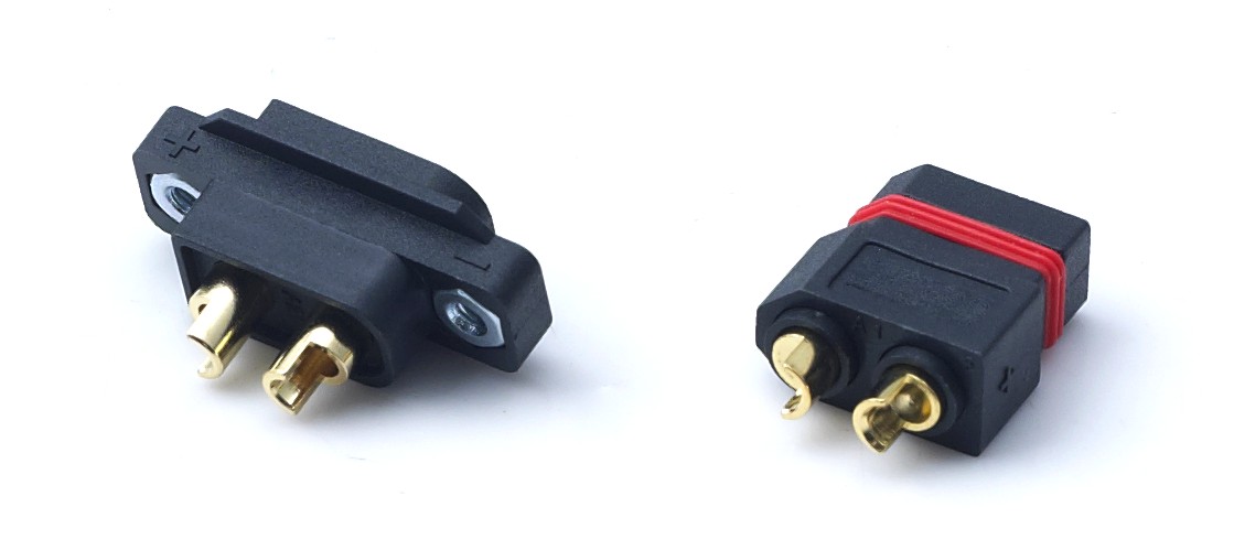
A waterproof pairing for exposed interfaces: the IP claim applies to the mated pair, so seal condition at every mating cycle matters as much as the rating itself.
Contact Resistance, Gold Plating and Heat
Contact resistance is the parameter that connects electrical and thermal behaviour. Every milliohm in the mated pair becomes heat at load, and two connectors with the same headline current rating can behave very differently once resistance is measured. Specify contact resistance in milliohms, together with the test current and method used to measure it, and treat the mated pair — not a single contact — as the unit under test.
Gold plating is usually chosen for stability rather than for raw ampacity. A gold finish resists surface oxidation and keeps low-current contact resistance steady, which is exactly what signal contacts in a 2+2 shell need over hundreds of mating cycles. When plating is on the specification, three details belong beside it: which contacts are plated, the plating thickness, and whether the finish survives the stated number of mating cycles without unacceptable resistance drift. Some designs plate power and signal contacts differently, and that is a legitimate engineering choice — it simply needs to be stated so the buyer is not comparing unlike parts.
Verification for both resistance and plating is the same electrical performance test report to IEC 60512 or GB/T 5095. Ask for the measurement conditions, not just the result.
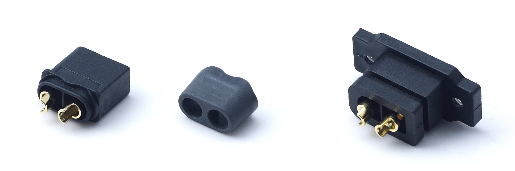
Mating hardware and contact condition are inspected together; resistance drift usually shows up first at the contact interface, not the housing.
Anti-Spark Pre-Charging and Hot-Plug Behaviour
An arc at connection is a design outcome, not bad luck. When a live lithium pack is connected to an ESC, inverter or power supply with significant input capacitance, the capacitor bank draws a large inrush current for a brief moment. That current can pit the contact surfaces, weld a contact, or damage the electronics behind the connector. The larger the capacitance and the higher the pack voltage, the more pronounced the effect.
Three strategies are common. A pre-charge resistor can be built into the connector assembly or the harness, limiting inrush while the capacitors fill. A sequenced contact design can mate a pre-charge path first and the main power contacts second, which is where the extra signal contacts in a 2+2 layout can be put to work. Or the pre-charge function can stay entirely external, in a separate plug or a switch, keeping the main connector simple. Each approach changes the mating procedure, and the procedure has to reach the field technicians, not just the design file.
If anti-spark behaviour is part of your specification, ask for the strategy in writing and for the evidence behind it. Where no pre-charge arrangement is documented, the safe assumption is that the connector is not intended for repeated hot-plug connection into a capacitive load at full voltage.
Mating, Locking and Vibration Exposure
Manual mating is a usability specification. Insertion and extraction force determine whether an operator can seat the connector by hand in cold weather or with gloves on, and a clear tactile or audible confirmation reduces half-mated connections, which are a leading cause of local heating. Grip area, keying and tool-free operation all belong in the drawing review, because a connector that needs a tool at the battery exchange cabinet changes the whole service procedure.
Locking has to survive the application. A latch or a secondary lock must hold the pair together under vibration, cable pull and impact, and retention force should be evidenced rather than assumed. This matters most where the connector is mounted on a moving mass: a spraying UAV, an AGV chassis, a garden tool or an electric two-wheeler. The manufacturer states that its connectors are built for frequent plugging and unplugging and for high- and low-temperature working conditions, and that the housing material is selected to resist cracking and loosening under sustained vibration — claims worth matching against the vibration and impact conditions of your own assembly.
The 1000 mating cycle target belongs here as a verification criterion rather than a slogan. To check it, request cycle test data produced under IEC 60512 or GB/T 5095 methods by an accredited laboratory, and read the test conditions: alignment during mating, plating thickness, whether cleaning was applied, and what resistance drift was accepted at the end of the run. Then align your field replacement interval with the confirmed figure. If no cycle data exists, treat 1000 cycles as unconfirmed for that part number.
Specification Sequence: Eight Steps From Datasheet to Purchase Order
- Fix the electrical envelope. Write continuous current, peak current with duration, system voltage and duty cycle as conditions — ambient, conductor size and mating counterpart included.
- Assign all four contacts. State what each power and signal contact carries, including whether either signal contact is reserved for pre-charge sequencing or a ground reference.
- Choose the IP class from the enclosure. IP40 inside a sealed housing, a waterproof pair for an exposed interface; confirm the rating applies to the mated condition.
- Set the temperature and derating basis. Confirm that the -20 °C to +120 °C window applies to the mated assembly and check contact temperature rise against your real ambient.
- Specify contact resistance and plating. Milliohms with test method, plus which contacts are gold-plated and to what thickness.
- Decide the anti-spark approach. Internal resistor, sequenced contacts or external pre-charge, with the mating procedure written down.
- Define mating, locking and service life. Insertion force, latch type, retention under vibration and the confirmed mating cycle figure.
- Assemble the verification dossier. ISO 9001:2015 and IATF 16949:2016 for the quality system, CE-LVD to EN 61984 for EU supply, IEC 60512 electrical performance, ASTM B117 salt spray, UL94 V-0 housing, RoHS 2.0 to IEC 62321 and REACH SVHC to Regulation (EC) No 1907/2006.
| Parameter | Why it decides the build | Document that verifies it |
|---|---|---|
| Continuous current | Sets steady-state heat in hover, robot or storage duty | IEC 60512 / GB/T 5095 electrical performance report |
| Peak current | Covers take-off, acceleration and inrush bursts | Same report, with duration and duty cycle stated |
| Rated voltage | Insulation margin above pack voltage and transients | CE-LVD declaration to EN 61984 |
| Operating temperature | Defines the usable ambient window for the mated pair | Model datasheet plus material data |
| IP class | Matches the interface to its real exposure | Datasheet mated condition; salt spray to ASTM B117 |
| Contact resistance | Converts directly into heat at load | Electrical performance report with test method |
| Plating | Keeps signal resistance stable across cycles | Drawing plus cycle test data |
| Anti-spark design | Prevents pitting and welded contacts on hot-plug | Written strategy and supporting test evidence |
| Locking and retention | Holds the pair under vibration and cable pull | Retention and vibration test data |
| Housing flammability | Limits fire spread from an internal fault | UL94 V-0 test report to UL 94 |
| Chemical compliance | Required for EU and North American market access | RoHS 2.0 (IEC 62321), REACH SVHC report |
| Mating cycles | Sets the field replacement and service interval | Cycle test data, 1000-cycle target confirmed |
Worked Example: DXT30U(2+2)-F(B)
AOYG DC Power Connector is a manufacturer and solution provider focused on high-current DC connection systems for lithium-ion smart devices. Company information supplied for this article states a 6,000 m² factory, 100 employees, a 25-engineer R&D team, a monthly capacity of 8,000 units, a 50% export ratio with main markets in the EU and USA, and IATF 16949:2016 automotive quality management system certification alongside ISO 9001:2015.
The DXT30U(2+2)-F(B) is a female 2+2 power-signal combo connector for lithium battery applications, and it is the cleanest illustration of how the parameter set above maps onto a real part number. Its documentation set lists the CE-LVD declaration to EN 61984, the electrical performance test report to IEC 60512 and GB/T 5095 from a CNAS, CMA and ISO 17025 accredited laboratory, a salt spray report to ASTM B117 and GB/T 10125, a UL94 V-0 flammability report to UL 94, a REACH SVHC report to Regulation (EC) No 1907/2006 and a RoHS 2.0 report to IEC 62321. In other words, the verification dossier described in step eight exists as a named document set for this model rather than as a promise.
Customisation is where a 2+2 project usually becomes specific. The manufacturer offers OEM and ODM production services, including customised size, current specification, pin position, wiring structure and logo printing, plus development of exclusive connector products based on the customer's application scenario and technical parameters. That matters when a robot chassis or a battery exchange cabinet needs a cable exit direction or a signal assignment that no catalogue part provides.
One boundary should be stated plainly: the existence of a report is not the value inside it. The continuous current, rated voltage, mated IP class and temperature range of DXT30U(2+2)-F(B) must be read from that model's own datasheet and test report before the drawing is released. This guide establishes which questions to ask and which documents answer them.
Where the 2+2 Format Fits
Agricultural spraying UAVs and FPV drones. Power and signal travel together from the pack to the flight controller, and the mating action happens dozens of times per week. Peak current dominates, vibration is continuous, and an anti-spark strategy protects both contacts and electronics.
Service robots and AGV handling robots. Duty is closer to steady state, so continuous current and contact resistance drift over many cycles become the deciding parameters, together with a locking mechanism that survives constant chassis motion.
Garden tools and portable cleaning equipment. Handheld use brings exposed interfaces, so a waterproof pairing plus salt spray evidence is more relevant than a high peak rating.
Portable energy storage, solar street light modules and battery exchange cabinets. Here the connector may sit untouched for long periods and then be mated under load. Temperature rise at continuous current and a documented pre-charge or hot-plug policy matter more than mating speed.
Electric two-wheelers and low-voltage lithium battery equipment. Repeated swap cycles make the mating cycle figure a maintenance planning input, not a marketing number. Adjacent low-voltage systems such as 5G base station backup power follow the same logic: a telecom site planning guide notes that 5G sites typically draw 11.5 to 14 kW with peaks reaching 19 kW, which raises the current the backup DC path must carry and makes connector resistance a system-level concern.
Frequently Asked Questions
Which compliance documents should come with a 2+2 high-current DC connector?
Ask for the RoHS 2.0 test report to IEC 62321, the REACH SVHC report to Regulation (EC) No 1907/2006, the UL94 V-0 housing report to UL 94, and a CE-LVD declaration to EN 61984 for EU supply. Add ISO 9001:2015 and, where consistency across batches matters, IATF 16949:2016. For the DXT30U(2+2)-F(B), these reports are listed in the manufacturer's documentation set for the model.
Can the pin position, current specification and wiring be customised?
Yes. The manufacturer provides OEM and ODM production services, including customised size, current specification, pin position, wiring structure and logo printing. ODM projects can go further into development of an exclusive connector based on the customer's application scenario and technical parameters, which is how non-standard cable exits or signal assignments are usually resolved.
OEM high-current DC power connector manufacturer for RC aircraft: what should be verified?
Verify five things: the conditions behind the current rating, the mating cycle data, the RoHS 2.0 and REACH SVHC reports, the UL94 V-0 housing report, and a sample you can test in your own harness. For RC aircraft duty, add the pre-charge strategy, because repeated connection into an ESC with large input capacitance is where contacts degrade fastest.
How do I verify a 1000 mating cycle target?
Request cycle test data produced to IEC 60512 or GB/T 5095 by a CNAS, CMA and ISO 17025 accredited laboratory, and read the test conditions: mating alignment, plating thickness, cleaning between cycles and the resistance drift accepted at the end of the run. If the report does not exist for the part number, treat 1000 cycles as unconfirmed and set the service interval from confirmed data only.
What are the MOQ, lead time and payment terms?
Purchasing terms stated for this range are a minimum order quantity of 2 units, a lead time of 30 to 45 days, FOB or CIF delivery terms, pre-shipment testing as the acceptance criterion, and 30/70 payment terms. Monthly capacity is stated as 8,000 units, which is the figure to check against your own ramp plan before committing to a launch date.
Can I test a sample before committing to a production run?
Yes. Samples can be ordered at the stated minimum quantity, and the manufacturer provides technical support for model selection, product adaptation analysis, assembly suggestions and sample debugging. Before you order, confirm the drawing against your real current, voltage and IP requirements; the contact details and product range are published at aoygvn.com.
Conclusion
A 2+2 power-signal high-current DC connector is specified by conditions, not by headlines. Continuous and peak current mean nothing without ambient, conductor and counterpart. Voltage needs an insulation declaration, temperature needs a material rating, IP needs a mated condition, and contact resistance needs a test method. Anti-spark behaviour, locking and mating cycles are design decisions that must be written down and then evidenced.
The practical approach is to fix the electrical envelope first, assign the four contacts second, and then build the verification dossier before the purchase order. When those documents exist for a specific part number — as they do for the DXT30U(2+2)-F(B) — the specification conversation shifts from claims to parameters, which is where a reliable lithium battery, UAV or energy storage build actually starts.
Have Questions or Need More Details?
Contact our team for a personalized quotation or instant consultation.
Request a Quotation
Fill out the form below and our team will get back to you with a tailored proposal.
WhatsApp Direct Chat
Prefer to chat in real-time? Message us on WhatsApp for instant assistance & quick answers.
- Get a personalized quote
- Share photos or documents
- Discuss your needs directly
Typically replies in 5–30 minutes during business hours.