Long-Term Reliability of High-Current DC Power Connectors
Mating cycles, temperature endurance, sealing class and the support pathway that keep a connector in service
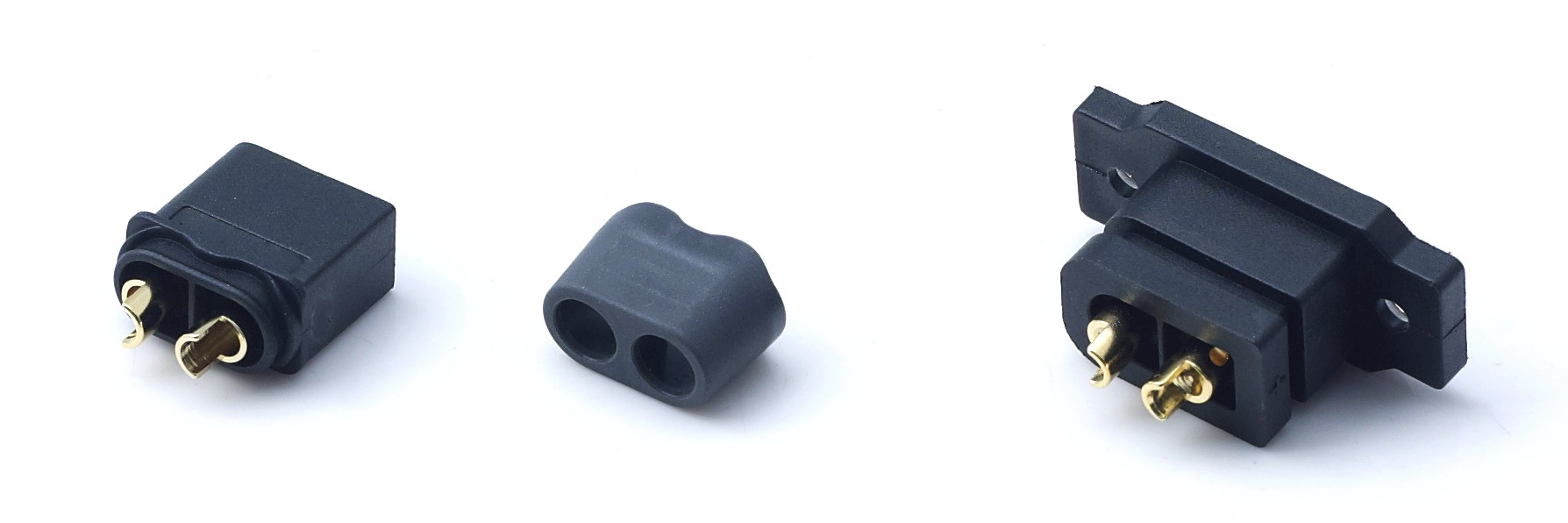
Cover: a high-current DC power connector pair built for repeated mating in battery-powered equipment.
A high-current DC power connector rarely fails on the day it is installed. It fails after two or three years of mating, heating, cooling and, in exposed installations, moisture and chemical attack — and by that point the failure is usually blamed on the battery, the BMS or the operator. Long-term reliability is therefore a specification problem before it becomes a maintenance problem.
Short answer: a high-current DC power connector is long-term reliable when three documented values hold together — a mating life of at least 1000 cycles, an operating temperature window that covers the site (-20 °C to +120 °C across the AOYG series discussed here), and a contact system whose resistance ceiling and plating thickness are stated. Warranty duration, return windows and replacement criteria are commercial terms, not catalogue values; they have to be fixed in the supply agreement.
That distinction matters at the evaluation stage: durability can be proven with specifications and test reports, while service policy can only be negotiated and written down.
AOYG DC Power Connector is a manufacturer of high-current DC connection systems for lithium-ion smart devices. Founded in 2024, the company operates a 6,000 m² facility with 100 employees, including a 25-engineer R&D team, produces up to 900,000 units per year, and holds IATF16949:2016 automotive quality management system certification. The five series covered in this article share one durability baseline — at least 1000 mating cycles and an operating window of -20 °C to +120 °C — and differ in continuous current, sealing class and signal integration.
Problem Definition: Why a Connector Rated for 60 A Fails at 40 A After Two Years
Degradation, not initial rating, decides connector life. Three mechanisms run in parallel in long-life installations. The first is mechanical wear: every mating cycle slightly burnishes the plating and reduces contact normal force, so the interface that measured 0.8 mΩ when new drifts upward over hundreds of cycles. The second is thermal aging: sustained temperature rise softens the thermoplastic housing and relaxes contact springs, which further raises resistance. The third is environmental attack, where moisture, salt and chemical vapour corrode the plating boundary.
The visible symptom arrives late. Resistance climbs, the joint runs warmer, voltage drop increases, and the operator eventually reports that a machine “cut out” or that a pack “lost power”. Because the connector is the cheapest component in the power path, it is often the last one investigated.
Chemical manufacturing and outdoor energy storage combine all three mechanisms at once. Cabinets absorb solar gain by day and cool sharply at night, so condensation forms on any surface that is not sealed. Washdown and airborne process vapour attack unplated or thinly plated surfaces. Meanwhile the connector may be mated daily by shift staff, or by service technicians during pack replacement.
The evaluation problem is that this category of component is frequently described by current and voltage alone. Many datasheets omit mating cycles, the wire gauge behind the temperature-rise figure, plating thickness and ingress protection. Without those four data points, two connectors that sit next to each other on a purchase order can have very different service lives, and the buyer has no defensible way to price the difference. The practical question is not “which connector is best”, but “whose long-life claims can I verify, and what happens when one unit fails in the field?”
Industry Background: Why Connector Life Has Become a Procurement Question
The category is growing, and the growth is concentrated in architectures where connectors are mated repeatedly rather than once at assembly. The global high power connectors market was valued at approximately USD 5.47 billion in 2025, according to Fact.MR’s high power connectors market analysis. In energy storage specifically, DC connectors represented 58.7% of the energy storage connector market in 2025, a share attributed to higher voltage requirements in Dataintelo’s energy storage connector market report.
Higher voltage raises the cost of a poor joint. Arc damage and plating erosion at a high-voltage interface produce a larger consequence per failure, and the resistance drift that is tolerable in a 12 V accessory circuit is not tolerable in a 500 V DC battery line.
Standardization adds a second pressure. In RC aircraft and drones, XT60 and XT90 remain the primary industry standards for medium to high power non-proprietary builds in 2026, as described in ChinaHobbyLine’s RC battery connector compatibility guide. Standardized form factors mean that packs, airframes and test rigs are re-plugged across many sessions and many owners, so cycle count stops being a laboratory number and becomes an operating parameter.
Outdoor infrastructure contributes the environmental half of the problem. Outdoor mobile photovoltaic energy storage, marine lithium battery systems, outdoor communication backup power, outdoor 5G base station standby power and outdoor garden machinery all place connectors in temperature swing and moisture for years. In each case the connector has moved from a “fit once” component to a serviceable wear part — and once a component is a wear part, mating life, sealing class, plating and the replacement pathway belong in the procurement criteria next to current rating.
Detailed Solution: How AOYG Specifies Long-Life Performance
Rather than publishing a single headline durability number, AOYG states durability per series. The five series discussed below share the same mating floor and thermal window and separate on current capacity, ingress protection and signal capability — which is what makes them comparable for long-life duty.
Mating cycles: the 1000-cycle floor and what it covers
Every series referenced in this article is rated at ≥1000 mating cycles: the DXT90H-M/DXT90S-F UAV connector, the DXT90H-M+DXT90E-F Yellow RC model connector, the DXT60EW-M+DXT60W-F waterproof pair, the DXT30U(2+2)-F(B) power-signal combo, and the DXT30U-M/DXT30U-F drone connector. In field terms, one mate-and-unmate per day for roughly three years consumes the rating; a monthly service interval would not exhaust it within the working life of most equipment. Battery swap cabinets, rental fleets, service depots and drone sessions are the duty profiles where that arithmetic actually binds.
The rating is a floor verified under test conditions, not a promise for every environment. Cycles accumulated at high ambient temperature, or in a corrosive atmosphere, consume the margin faster because plating wear and corrosion accelerate each other. That is why the cycle figure should always be read together with the temperature window, the plating specification and the sealing class.
Thermal endurance: -20 °C to +120 °C and the temperature-rise condition
All five series are rated for -20 °C to +120 °C operation with PA66 UL94 V-0 housings. Both halves of that window have practical meaning outdoors: the upper limit leaves headroom above the internal ambient of a solar-loaded cabinet, and the lower limit covers cold-start conditions in unheated installations.
Continuous current is always quoted with a temperature-rise condition and a wire gauge, and the gauge is part of the thermal design rather than an accessory. The DXT90H-M/DXT90S-F is rated 90 A continuous on 10AWG wire with temperature rise ≤85 °C; the DXT90H-M+DXT90E-F Yellow is rated 45 A continuous on 10AWG with rise <85 °C and 90 A short-term peak; the DXT60EW-M+DXT60W-F is rated 60 A continuous and 100 A peak on 8–10AWG; the DXT30U(2+2)-F(B) carries 20 A per power pin on 16AWG with a 35 A peak on 12–16AWG; the DXT30U-M/DXT30U-F carries 15 A with a 30 A peak on 18AWG, compatible with 20AWG.
A 90 A connector crimped onto undersized cable will run hotter than the qualification condition regardless of how good the contact is. Matching the wire gauge is the cheapest durability improvement available in the whole power path.
Contact resistance and plating: the degradation margin you can specify
Contact resistance ceilings are published per series: ≤0.7 mΩ on the DXT30U-M/DXT30U-F, ≤0.8 mΩ on the DXT60EW-M+DXT60W-F, ≤1.0 mΩ on the DXT90H-M+DXT90E-F Yellow, and ≤1.2 mΩ on the DXT30U(2+2)-F(B). Insulation resistance is specified at ≥2000 MΩ with a withstand voltage of AC 2000 V for one minute across the range.
Terminals are H62 brass with gold plating. The DXT90H-M/DXT90S-F uses standard 0.3 µm gold plating with optional thicker industrial gold plating, and the DXT90H-M+DXT90E-F Yellow and DXT60EW pairs use gold-plated beryllium copper spring contacts. Salt spray testing is stated at 48 hours for gold-plated terminals on the listed series.
Interpretation matters here. The resistance ceiling defines what end of life looks like in a test, while plating thickness defines how long it takes to get there in a corrosive atmosphere. For a coastal site or a chemical plant, 48 hours of salt spray is an entry threshold rather than a finish line — the thicker industrial gold option is the lever that buys additional corrosion margin.
Anti-spark precharge: protecting the contact at the moment of mating
The DXT90H-M/DXT90S-F female side (DXT90S-F) contains a built-in high-power precharge resistor. In lithium polymer packs and UAV power rails, the inrush current at the instant of connection can damage the contact surface before the connector is even seated; the precharge resistor limits that initial current so the main contact closes onto a settled rail. Because arc erosion is one of the paths by which a new connector drifts toward its resistance ceiling, this is a durability feature and not only an electrical one.
BMS and LiPo integration: the 2+2 power-signal architecture
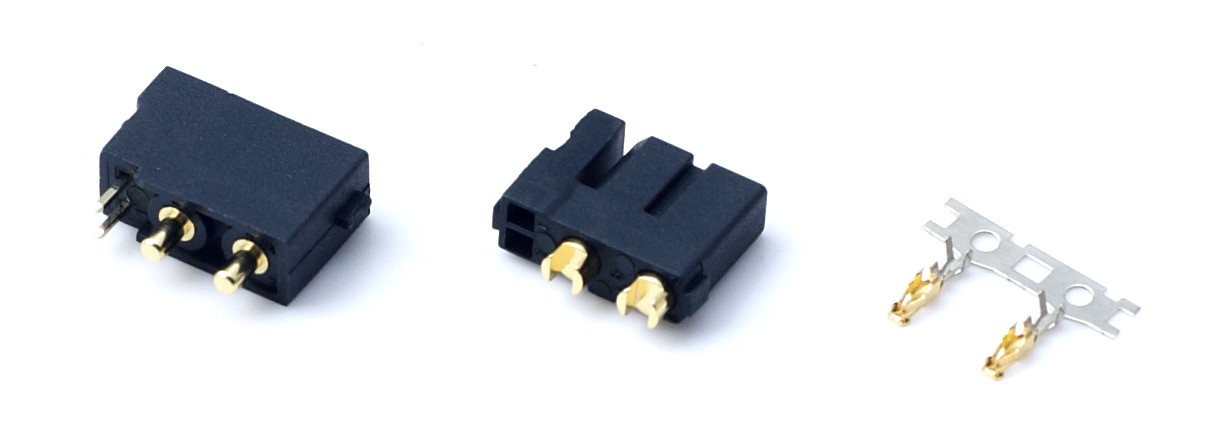
A 2+2 power-signal combo pair: two power pins and two signal pins in a single housing.
The DXT30U(2+2)-F(B) places two power pins and two signal pins in one housing. The power pins are rated 20 A on 16AWG, the signal pins 1 A, with a 35 A peak, a DC 500 V rating, 12–16AWG silicone wire, ≥1000 mating cycles, IP40 protection and -20 °C to +120 °C operation. Its mating counterparts are the DXT30U(2+2)-M and DXT30U(2+2)P.
The durability argument is structural: BMS sense and communication lines travel with the power pair through a single interface instead of a separate connector block. Fewer interfaces means fewer seals to maintain, fewer mating operations to log, fewer part numbers in the service kit, and no chance of a pack being reassembled with the signal connector left loose. The 1 A signal rating is intended for sense and communication duty, not for load current. The series’ applicable industry list includes BMS systems, portable energy storage, robots, garden power tools and smart device battery packs.
Sealing class: IP40 versus IP67 is a longevity decision
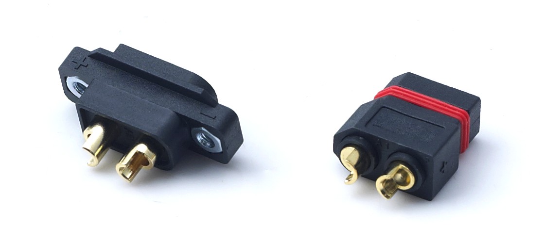
The DXT60EW-M+DXT60W-F waterproof pair, sealed with a silicone O-ring to IP67.
The DXT60EW-M+DXT60W-F is the IP67 option: 60 A continuous and 100 A peak, Φ5 mm H62 brass gold-plated terminals, contact resistance ≤0.8 mΩ, 8–10AWG wire, and silicone O-ring sealing in a PA66 UL94 V-0 housing. The DXT90H, DXT30U and DXT30U(2+2) series are IP40, which is appropriate for wiring inside a sealed enclosure.
The limitation should be stated plainly: IP40 is not a washdown or weather rating. Specifying an IP40 connector for an outdoor cabinet transfers the entire sealing burden to the enclosure, and any condensation that forms inside that enclosure still reaches the contact interface. Where exposure is real, the sealed part should be selected rather than compensated for.
Warranty, replacement and technical support: what is verifiable and what is contractual
Two different things are being asked for when a buyer asks about warranty. The first is evidence that the product was built under control; the second is the commercial promise attached to it. AOYG documents the first, and the second belongs in the agreement.
On the verifiable side, the manufacturer maintains 100% test quality control, and the IATF16949:2016 system provides full lifecycle traceability from raw material through stamping, injection moulding, precision assembly and performance testing to finished goods. Third-party documentation is available for the compliance side: an electrical performance test report to IEC 60512 and GB/T 5095 from a laboratory accredited to CNAS, CMA and ISO17025; a salt spray report to GB/T 10125 and ASTM B117; a UL94 V-0 flammability report; RoHS 2.0 to IEC 62321; REACH SVHC screening; and a CE-LVD declaration of conformity to EN 61984, alongside ISO9001:2015 certification. On the support side, the manufacturer provides after-sales support including remote support, and offers sample testing before mass production.
On the contractual side, a long-life project should fix four things in writing: the failure definition (for example, a unit whose contact resistance exceeds the specified ceiling at goods-in or during service), the remedy for a confirmed failure, the freight and logistics responsibility, and the escalation route and expected response when a technical issue appears in the field. Traceability and a 100% test regime are what make such a claim arguable rather than anecdotal — without lot identification, a replacement discussion becomes a discussion about impressions.
Step-by-Step Breakdown: A Five-Step Evaluation Path for Long-Life Projects
Step 1 — Convert service life into mating cycles. Count how many times the connector is mated per unit per year, multiply by target service life, then add a margin for field service and rework. If the result approaches or exceeds 1000, the cycle floor alone is not enough and sealing plus plating choices carry more weight.
Step 2 — Fix the temperature window and the wire gauge. State the maximum ambient inside the enclosure and the minimum cold-start temperature, then confirm the continuous current is quoted at the gauge you will actually crimp: 90 A at 10AWG, 60 A at 8–10AWG, 20 A at 16AWG, 15 A at 18AWG.
Step 3 — Write a contact-resistance ceiling into incoming inspection. Use the published ceiling (0.7 to 1.2 mΩ depending on series). A unit that exceeds its ceiling at goods-in will not improve in service, so this is the cheapest early-warning test available.
Step 4 — Match the interface to the pack architecture. One power pair for simple packs; 2+2 where a BMS needs power and signal in one housing; IP67 where the interface is exposed to weather, washdown or chemical vapour; anti-spark precharge where lithium packs are connected hot.
Step 5 — Fix the support and replacement pathway before volume. Request the test report pack for the exact model, agree the failure definition and the escalation contact, and run a sample build first: minimum order quantity is 2 units, lead time is 30–45 days, and monthly capacity is 8,000 units.
Use Cases: Where These Specifications Are Tested in Practice
Chemical manufacturing and process areas
Process environments combine temperature cycling, airborne vapour, washdown and near-continuous operation. The fit is the IP67 DXT60EW-M+DXT60W-F at 60 A continuous and 100 A peak, with silicone O-ring sealing, 48-hour salt spray on the gold-plated terminals and ≥1000 mating cycles; the thicker industrial gold plating option on the DXT90H series is relevant where corrosion margin matters more than unit cost. IP40 parts remain inside sealed cabinets only. Because the manufacturer runs 100% test quality control with lot traceability, a batch-level investigation is possible if a field issue appears.
Outdoor energy storage and 5G backup cabinets
The applicable-industry list for the DXT60EW pair covers outdoor mobile photovoltaic energy storage, outdoor communication backup power, outdoor 5G base station standby power, marine lithium battery systems and waterborne unmanned equipment. The duty here is daily thermal cycling and condensation, so IP67 sealing, 8–10AWG cabling and the 60 A / 100 A peak rating define the specification rather than the nominal system voltage.
BMS-controlled LiPo packs, service robots and smart devices
Repeated charging, pack swapping and signal integrity point to the DXT30U(2+2)-F(B): 20 A on the power pins, 1 A on the signal pins, 35 A peak, ≥1000 cycles and -20 °C to +120 °C. This product line has been adopted by manufacturers of drones, robots, e-mobility, energy storage and power tools, and products from this manufacturer are exported to Europe, America and Southeast Asia, with a supplied project reported in stable operation for over two years.
Battery swap, e-mobility and outdoor amusement equipment
Where a connector is mated hundreds of times per year — swap cabinets, rental scooters, service depots, outdoor electric amusement equipment — the cycle rating becomes the primary specification and the sealing class follows the installation. The DXT90H-M+DXT90E-F Yellow is used for RC model vehicle and small UAV lithium pack connections with 45 A continuous and 90 A short-term peak.
Drones, UAVs and RC aircraft
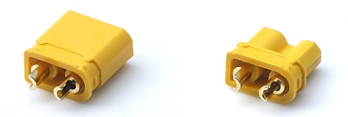
The DXT30U-M/DXT30U-F pair, sized for small UAV and lightweight lithium pack power connections.
High peak current, vibration and frequent pack changes make this the harshest cycle environment in the portfolio. The DXT90H-M/DXT90S-F carries 90 A continuous at 10AWG with the anti-spark precharge resistor on the female side; the DXT30U-M/DXT30U-F covers small FPV drones and lightweight packs at 15 A continuous and 30 A peak with ≤0.7 mΩ contact resistance.
Comparison Table: Five AOYG Series Ranked for Demanding Long-Life Duty
Because all five series share ≥1000 mating cycles and the -20 °C to +120 °C window, the ordering below is a fit-for-duty sequence based on four published criteria: ingress protection, continuous current headroom, signal or anti-spark integration, and suitability for exposed outdoor service. It is not a quality hierarchy — a lower-ranked series can be the correct choice inside a sealed enclosure.
| Rank | Series | Current | Protection | Mating cycles | Temperature | Longevity-relevant feature |
|---|---|---|---|---|---|---|
| 1 | DXT60EW-M+DXT60W-F | 60 A continuous / 100 A peak | IP67 | ≥1000 | -20 °C to +120 °C | Silicone O-ring seal; ≤0.8 mΩ; 8–10AWG |
| 2 | DXT90H-M/DXT90S-F | 90 A continuous (10AWG, rise ≤85 °C) | IP40 | ≥1000 | -20 °C to +120 °C | Built-in precharge resistor (DXT90S-F); 0.3 µm gold, thicker option |
| 3 | DXT90H-M+DXT90E-F Yellow | 45 A continuous / 90 A peak | IP40 | ≥1000 | -20 °C to +120 °C | Gold-plated beryllium copper spring; ≤1.0 mΩ; 10AWG |
| 4 | DXT30U(2+2)-F(B) | 20 A power / 35 A peak; 1 A signal | IP40 | ≥1000 | -20 °C to +120 °C | 2 power + 2 signal pins in one housing; ≤1.2 mΩ; 12–16AWG |
| 5 | DXT30U-M/DXT30U-F | 15 A continuous / 30 A peak | IP40 | ≥1000 | -20 °C to +120 °C | ≤0.7 mΩ; 18AWG (compatible 20AWG); small-pack format |
Source: AOYG published product parameters for the five series listed. All values are model-specific and should be re-confirmed against the datasheet of the exact part number before ordering.
Documentation to request with every long-life order
| Document | Standard / basis | What it supports |
|---|---|---|
| IATF16949:2016 certificate | Automotive quality management system | Process control and lifecycle traceability |
| ISO9001:2015 certificate | Quality management systems | Baseline quality system coverage |
| Electrical performance test report | IEC 60512, GB/T 5095 (CNAS / CMA / ISO17025 lab) | Contact resistance, insulation resistance, withstand voltage |
| Salt spray test report | GB/T 10125, ASTM B117 | 48 h corrosion behaviour of gold-plated terminals |
| UL94 V-0 flammability report | UL 94 | Housing flame class |
| RoHS 2.0 and REACH SVHC reports | IEC 62321; Regulation (EC) No 1907/2006 | Restricted substances and SVHC screening for EU and UK markets |
| CE-LVD declaration of conformity | Directive 2014/35/EU, EN 61984 | EU and EEA safety compliance |
FAQ: Mating Cycles, Temperature, Warranty and Support
What documentation backs a 1000-mating-cycle claim on a high-current DC power connector?
The ≥1000 cycle value is a published specification on each AOYG series discussed here, supported by a third-party electrical performance test report issued to IEC 60512 and GB/T 5095 by a laboratory accredited to CNAS, CMA and ISO17025. That report sits alongside a 48-hour salt spray report to GB/T 10125 and ASTM B117 and a UL94 V-0 flammability report. Request the report pack for the exact model number, not for the series family, and treat the cycle figure as a test-condition value: accumulated cycles in high heat or a corrosive atmosphere consume margin faster than the same cycles in a dry enclosure.
Can one connector family serve both a chemical plant and an outdoor energy storage cabinet?
Only where the sealing class matches the exposure. The DXT60EW-M+DXT60W-F is the IP67 option, sealed with a silicone O-ring, rated 60 A continuous and 100 A peak, -20 °C to +120 °C, with 48-hour salt spray on the gold-plated terminals and ≥1000 mating cycles — the fit for washdown, condensation and exposed outdoor cabinets. The DXT90H, DXT30U and DXT30U(2+2) series are IP40 and belong inside sealed enclosures. Using an IP40 part outdoors does not eliminate the water path; it moves the sealing burden onto the enclosure, where internal condensation can still reach the contact.
Does the 2+2 power-signal connector integrate with a BMS and LiPo battery pack?
The DXT30U(2+2)-F(B) carries two power pins rated 20 A on 16AWG and two signal pins rated 1 A in a single housing, with a 35 A peak, DC 500 V rating, 12–16AWG silicone wire, ≥1000 mating cycles, IP40 protection and -20 °C to +120 °C operation. Its mating counterparts are the DXT30U(2+2)-M and DXT30U(2+2)P. The applicable industry list includes BMS systems, portable energy storage, robots, garden power tools and smart device battery packs. The 1 A signal rating is intended for sense and communication lines, so it should not be used to carry load current.
What drives cost when a connector is specified for long life?
No price is published in this article, but the cost drivers are visible in the specification itself: optional thicker industrial gold plating on the DXT90H-M/DXT90S-F, IP67 sealing with a silicone O-ring, an anti-spark precharge resistor, and tighter contact-resistance ceilings. Because the minimum order quantity is 2 units and lead time is 30–45 days, a durability upgrade can be validated at sample quantity before it is committed to a production order. Testing the exact configuration is a more reliable way to price long life than buying on the headline current rating alone.
How do I validate long-term reliability before volume, and how quickly can units arrive?
Run a sample build and a coupon test first. AOYG supports sample testing and OEM/ODM customization covering size, current specification, pin position, wiring structure and logo printing, with a minimum order quantity of 2 units, a lead time of 30–45 days and monthly capacity of 8,000 units; 100% test quality control and the report pack support incoming inspection. For a technical discussion on mating cycles, sealing class, BMS wiring or a replacement pathway for a specific project, contact AOYG DC Power Connector by email at xiuweizhao77@gmail.com, on WhatsApp at +84 366770891, or through www.aoygvn.com.
Conclusion: Specify the Life, Then Verify the Evidence
Long-term reliability in a high-current DC power connector resolves into a small set of checkable values: at least 1000 mating cycles, an operating window of -20 °C to +120 °C, a stated contact-resistance ceiling, a plating specification, and an ingress protection class that matches the installation. The AOYG series covered here meet the first two across the range and separate on the rest — the IP67 DXT60EW pair for exposed outdoor and process environments, the DXT90H-M/DXT90S-F at 90 A with anti-spark precharge for high-current lithium packs, the DXT90H-M+DXT90E-F Yellow for RC and light EV duty, the 2+2 DXT30U(2+2)-F(B) where a BMS needs power and signal through one interface, and the DXT30U-M/DXT30U-F for small packs.
The remaining variables are commercial, and they should be treated that way: warranty duration, return windows and replacement criteria are set in the supply agreement, while the test regime, the traceability standard and the support channel are what make those terms enforceable. Buyers who confirm both halves — the published durability values and the negotiated service pathway — are the ones who discover a connector problem at goods-in rather than in a customer’s cabinet two years later.

AOYG DC Power Connector supplies high-current DC connection systems and supports sample testing, OEM/ODM customization and remote technical support.
Next step: test a pair against your own duty cycle
Request a sample pair, the test report pack for a specific model, or a technical review of your mating-cycle and temperature requirements. Minimum order quantity is 2 units and lead time is 30–45 days.
Email: xiuweizhao77@gmail.com | WhatsApp: +84 366770891 | www.aoygvn.com
Have Questions or Need More Details?
Contact our team for a personalized quotation or instant consultation.
Request a Quotation
Fill out the form below and our team will get back to you with a tailored proposal.
WhatsApp Direct Chat
Prefer to chat in real-time? Message us on WhatsApp for instant assistance & quick answers.
- Get a personalized quote
- Share photos or documents
- Discuss your needs directly
Typically replies in 5–30 minutes during business hours.