Hydraulic Cylinder Guide: Pressure Ratings, Stroke Length & Mounting Styles
Hydraulic Cylinder Guide: Pressure Ratings, Stroke Length & Mounting Styles
A hydraulic cylinder fits a machine only when three parameters are confirmed at the same time: the continuous working pressure the cylinder is rated to hold, the stroke length that produces the required travel inside the available closed length, and the mounting style that transfers force into the structure without adding side load. Pressure tells you what the cylinder can survive, stroke tells you how far the machine can move, and mounting tells you whether the force reaches the load in a straight line. Apex Hydraulic Co., Ltd., a custom hydraulic cylinder manufacturer established in 2009 in Qingdao, Shandong Province, China, builds cylinders and hydraulic power units against these three parameters from approved drawings, with dimensional inspection, pressure testing, leakage testing and full-stroke functional testing before shipment.
Why Cylinder Selections Fail Before the Cylinder Even Arrives
Most hydraulic cylinder problems are specification problems, not manufacturing problems. Three recurring failures appear in mobile and industrial equipment projects.
Pressure mismatch. A cylinder is ordered against the nominal pressure of the machine, while the actual relief setting, pressure spikes from shock loading, or a regeneration circuit pushes peak pressure higher. When the cylinder is engineered without confirming maximum system pressure first, the sealing system and wall thickness may be selected for the wrong load case. Apex Hydraulic states this constraint explicitly in its heavy-duty and long-stroke cylinder specifications: maximum system pressure must be confirmed before engineering approval, and proof-test pressure is defined in the approved inspection and testing plan.
Stroke and envelope mismatch. A cylinder that delivers the correct travel but does not fit the retracted installation envelope forces frame modification. This is the core reason telescopic cylinders exist: they produce a long working stroke from a compact retracted length. The Apex HTC-compatible series, for example, covers strokes from 78 to 144 inches with a retracted length between 34.75 and 48.75 inches, and the underbody L-series covers a 676–2,057 mm power stroke with a closed length of 367–598 mm.
Mounting mismatch. Force that enters a machine through the wrong mount geometry produces side loading, rod deflection and premature seal wear. Mounting style, pin diameter and mounting width are therefore not accessories; they are part of the cylinder's structural definition.
Industry Background: A Market Driven by Mobile Equipment
The global hydraulic cylinder market was valued at USD 15.7 billion in 2024 and is projected to reach USD 24.7 billion by 2034, according to Global Market Insights. Grand View Research reports that welded hydraulic cylinders held a 53.6% market share in 2025, a figure consistent with the durability requirement of heavy-duty applications, and that double-acting cylinders account for 71.6% of the function segment by revenue.
Demand is concentrated where machines work, not where they are assembled. Mobile applications including construction and agriculture represent 51.8% of hydraulic cylinder market demand, and bore sizes up to 150 mm held the largest share of 61.6% in 2025. Telescopic cylinders formed a USD 2,225.1 million segment in 2024, with a projected CAGR of 5.9%. Industrial manufacturing is expected to be the fastest-growing end-user segment at a 6.12% CAGR through 2031, according to Mordor Intelligence.
Standardization explains why mounting style deserves early attention. ISO 6022:2006 establishes mounting dimensions for single-rod hydraulic cylinders in the 250 bar series, ISO 6020-2:2015 specifies mounting dimensions for 160 bar compact cylinders, and NFPA/T3.6.7 R3-2009 (R2024) defines square-head industrial cylinder mounting dimensions in North America. These standards exist to preserve interchangeability. On mobile equipment, however, mounting geometry is frequently defined by the machine envelope rather than by a catalogue standard, which is why build-to-print documentation — the original part number, drawing, sample or verified installation dimensions — remains the practical basis for selection.
The Three Selection Parameters in Detail
1. Pressure Rating: Rated Pressure, Maximum System Pressure and Proof Pressure
Working pressure is an application value, not a catalogue value alone. The engineering sequence is to establish the machine's normal working pressure, confirm the maximum system pressure including relief and spike conditions, and then select or engineer the cylinder so that its rated working pressure covers the first and its proof-test plan covers the second.
Apex Hydraulic cylinder families publish different pressure references because they serve different duty classes:
- Single-acting ram / plunger cylinders (APEX-CSPC Series): working pressure 160–350 bar, with maximum design pressure up to 500 bar for specially engineered configurations.
- Heavy-duty high-pressure cylinders (APEX-CHDC Series): working pressure and maximum system pressure customized to the approved hydraulic-system specification, with proof-test pressure defined in the approved inspection and testing plan.
- North American welded series (HBU, HCL, HTG): rated working pressure up to 3,000 PSI.
- Dump truck telescopic cylinders (S Series): nominal working pressure 2,000 PSI / 140 bar, with higher pressure applications subject to engineering evaluation.
- Underbody dump trailer telescopic cylinders (L120 / L105 / L90 / L75): maximum working pressure 200–220 bar depending on series.
- Position-sensing and mill-duty cylinders (APEX-CPSC, APEX-CMDC): working pressure up to 250 bar for the normal product range.
Hydraulic circuit settings matter as much as cylinder ratings. On the 12K hydraulic trailer jack kit, for example, the extend / raising-port relief setting is 3,200 PSI and the retract / lowering-port relief setting is 1,500 PSI, against a maximum working pressure of 3,200 PSI and a maximum flow rate of 2 GPM. Specifying a cylinder without aligning it to those circuit values is a common source of warranty disputes.
2. Stroke Length: Travel, Closed Length and Buckling Verification
Stroke length is the travel the rod extends; closed length and extended pin-to-pin dimensions determine whether that travel is usable. In long-stroke compression applications, the rod also becomes a column. Apex Hydraulic treats this as an engineering gate rather than a catalogue choice: on the long-stroke series, piston rod diameter is determined through load, unsupported length, buckling and deflection calculations, rod buckling verification is required for long-stroke compression applications, and rod deflection verification is required for horizontal and inclined installations.
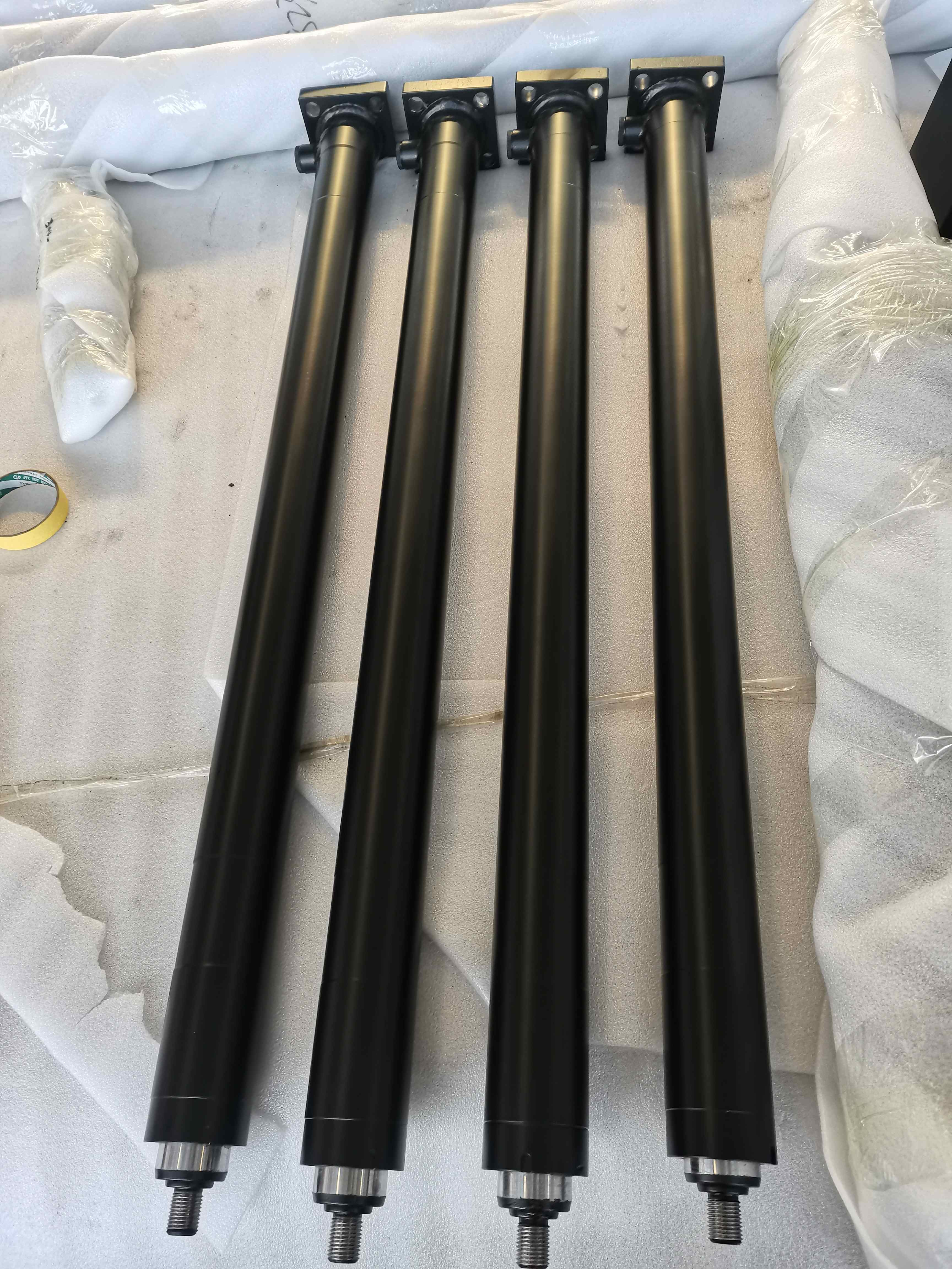
Where installation space is short but travel is long, a multi-stage telescopic construction is used. Apex telescopic cylinders extend from the largest stage to the smallest stage and retract from the smallest stage to the largest stage unless the approved design specifies otherwise. The underbody L-series delivers a 676–2,057 mm stroke with 3–6 stages, and the S Series general stroke range runs from 36 to 500 inches, with current stocking models covering 72–265 inches. Front-end tipper cylinders of the FC, FE and FEE families reach 3,880–8,130 mm strokes on the listed FC standard models.
A practical rule follows from these numbers: define stroke from the machine's required movement, then treat closed length as the constraint, and only then decide whether a single-stage or telescopic cylinder satisfies both.
3. Rod Diameter: Load, Buckling and Surface Integrity
Piston rod diameter is calculated, not assumed. The Apex heavy-duty high-pressure specification states that rod diameter is determined by load direction, unsupported length, buckling calculation and side-load conditions, and that column stability requires piston-rod buckling verification for long-stroke compression applications. Side-load conditions must be evaluated during engineering review, and where significant side loading is expected on single-acting ram cylinders, external guides are recommended.
Surface integrity is the second half of rod design. Published Apex welded cylinder data specifies an induction-hardened rod with a core hardness of 45–50 HRC, hard chrome plating at 0.001 inch, a final rod surface hardness of 69–71 HRC, and a corrosion test of 96 hours according to ASTM B117-07a. Those values describe wear and corrosion behaviour at the rod, which is the component most exposed to dust, mud, salt spray and abrasive material.
4. Mounting Styles: How Force Enters the Machine
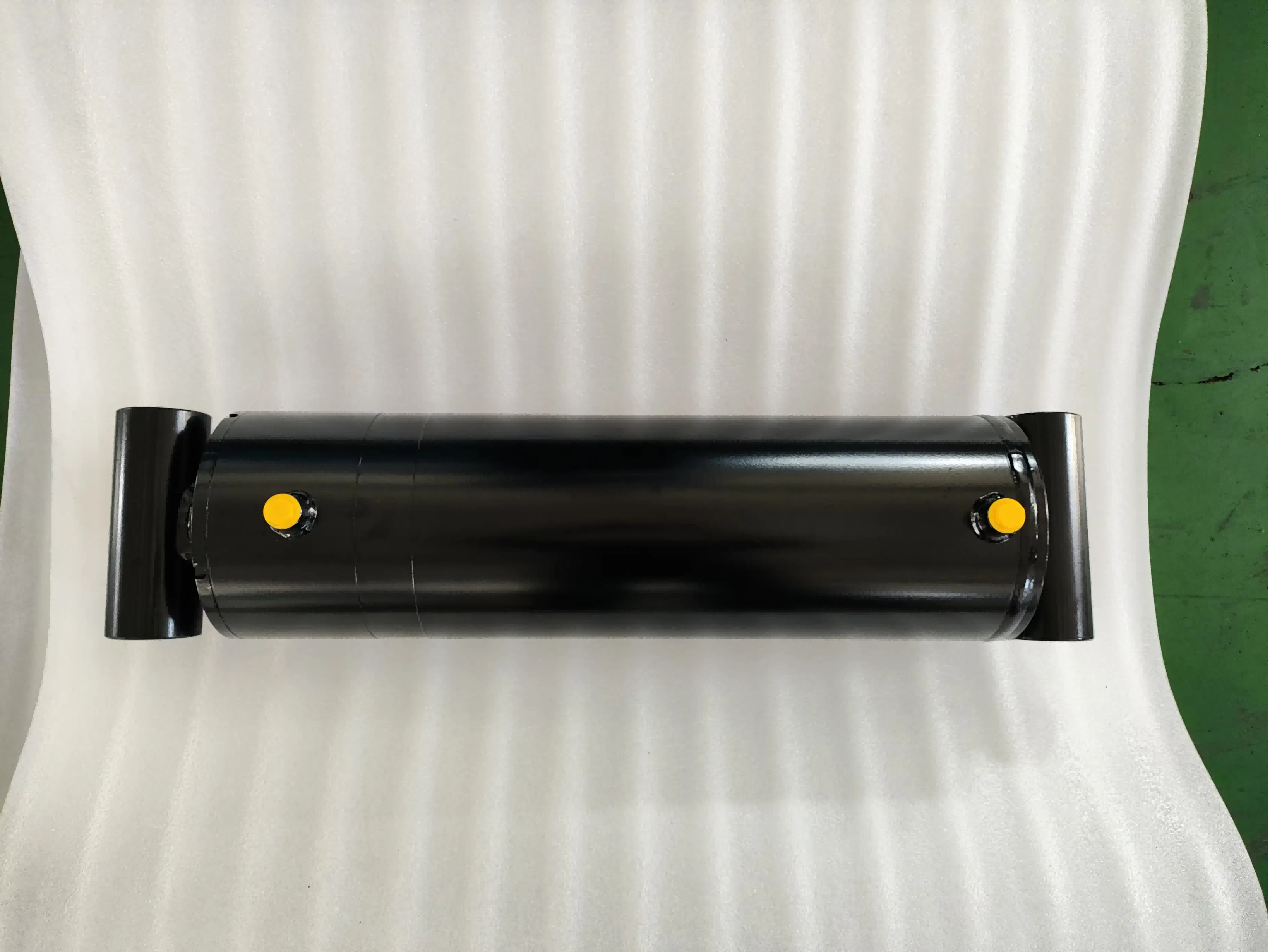
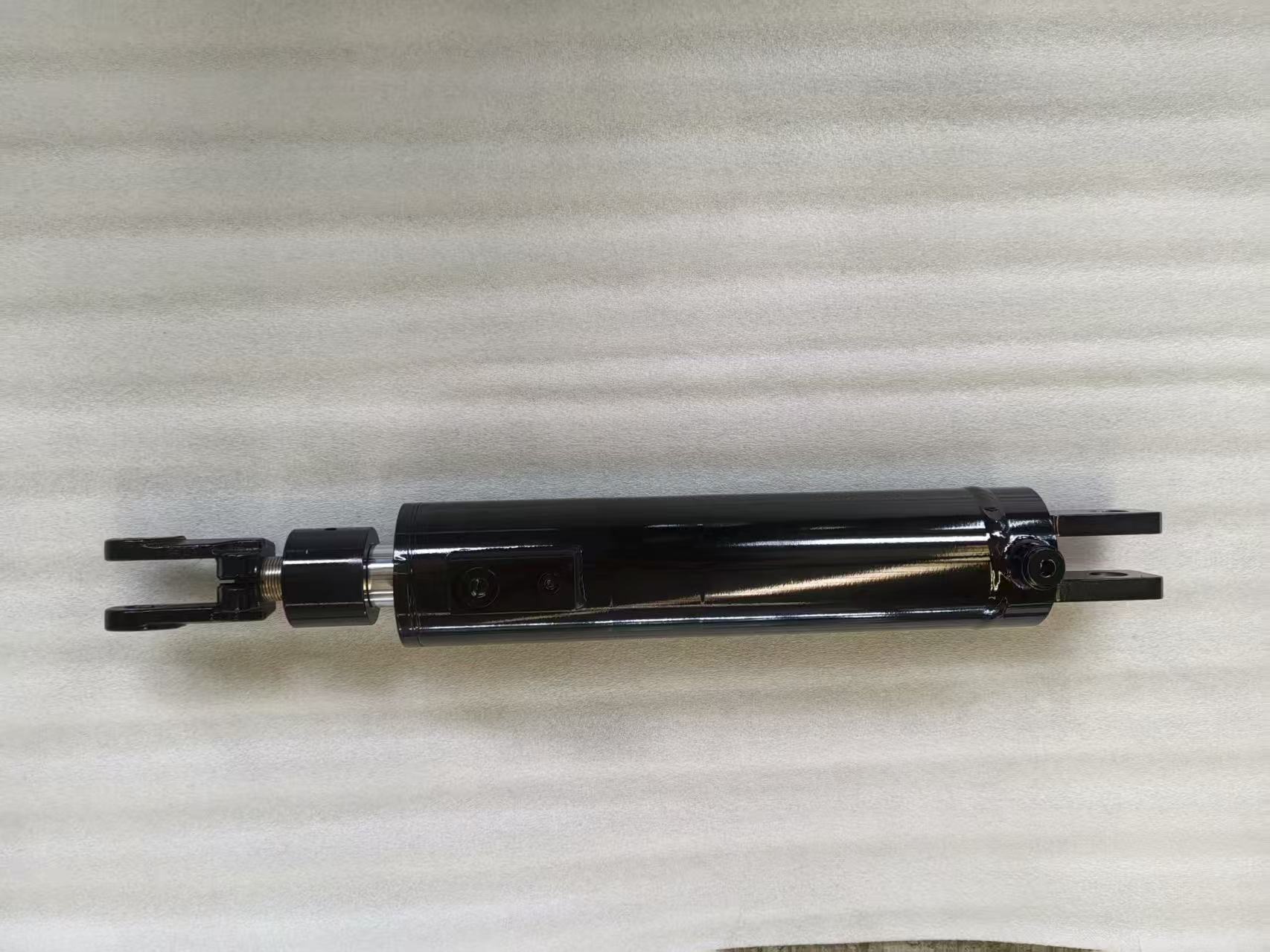
Mounting style decides the load path. Apex custom cylinders are offered with cross-tube, clevis, pin-eye, trunnion, flange, foot mount, spherical bearing or customer-specific mounting, and rod-end connections including clevis, pin-eye, threaded rod end, spherical bearing or custom machined interface. Specific product families narrow that list in ways that matter to buyers:
- HBU Series: cross-tube bushing mount, bore 1.5–5.0 in, stroke 4–48 in, bushing inside diameter 0.75–1.75 in.
- HCL Series: fixed clevis mount, bore 1.5–5.0 in, stroke 4–36 in, pin diameter options of 1.0, 1.25 and 1.5 in.
- HTG Series: adjustable threaded female clevis with locking bolt, bore 2.0–4.0 in, stroke 4–36 in, 1.0 in pin diameter.
- Underbody telescopic L-series: transverse pivot / trunnion mounting with an induction-hardened ball upper connection permitting up to 30 degrees of articulation; rod-eye options with pin are also available.
- HTC-compatible dump trailer cylinders: front-mount inverted installation with a 1.00 inch rod pin hole.
Two engineering consequences follow. First, angular movement must be accommodated somewhere in the linkage; spherical bearings or ball connections are used where the machine geometry changes angle through the stroke. Second, mounting pins and bushings are wear parts — the welded series uses replaceable bushings, and the grapple cylinder specification notes that replaceable bushings simplify attachment maintenance and reduce lifecycle cost.
Step-by-Step Breakdown: A Repeatable Selection Sequence
The following sequence reflects the input data Apex Hydraulic requires for custom cylinder and power unit projects. Working through it in order prevents the three mismatches described earlier.
- Identify equipment type and cylinder function. Boom, arm, bucket, lift, tilt, steering, ejector, tailgate, packer, jib, winch or stabilizer duty defines the load case. Replacement projects require the machine model and serial number where a reference part number is used.
- Record pressure values separately. Capture required working pressure and maximum system pressure, and include relief valve settings if they are already defined. Maximum system pressure must be confirmed before engineering approval.
- Record the movement envelope. Required stroke length, retracted pin-to-pin length, extended pin-to-pin length and the available installation envelope are all needed; extended length is derived from retracted length plus effective stroke, and must be validated against the drawing.
- Define the load. Required push force and pull force, normal working load, maximum peak load, load direction, unsupported rod length, side-load conditions and duty cycle determine bore, rod diameter and bearing selection. Rated push force is calculated from piston area and rated pull force from annular piston area at the specified working pressure.
- Select the mounting style and interface dimensions. Confirm mounting style, mounting pin diameter, mounting width and permitted angular movement. On pivot-mounted equipment, unequal or misaligned pin centres are a frequent cause of side loading.
- Specify ports and routing. Apex cylinder port options include SAE ORB, NPT, BSPP, BSPT, metric thread, SAE flange or customer-specified connections, with port position customized to hose routing and installation clearance. Port size is selected according to required flow rate and acceptable pressure loss.
- Confirm environment and finishing. Operating temperature, hydraulic fluid type, corrosion-protection requirement and required paint colour complete the specification. On the welded North American series, standard hydraulic ports are SAE O-ring boss with NPT available as an option, with a black industrial coating as standard finish.
Documentation that removes ambiguity: equipment type, cylinder function, existing part number, existing cylinder photograph, installation drawing or sample cylinder, bore diameter, rod diameter, stroke, retracted and extended pin-to-pin length, working and maximum system pressure, push and pull force, mounting style, pin diameter, mounting width, port type and position, operating temperature, fluid type, duty cycle, corrosion requirement, paint colour, annual demand and order quantity.
Use Cases: Where Each Parameter Set Is Applied
Dump trailers with underbody tipping. Compact closed length is the governing constraint because the cylinder sits beneath the load floor. The L-series uses 3–6 stages to reach a 676–2,057 mm stroke from a 367–598 mm closed length, with tipping capacity of 4–21 tons and 30 degrees of ball articulation, using single-acting extension with gravity return.
Dump trucks with front-end telescopic cylinders. The S Series works on single-acting extension and gravity return at a nominal 2,000 PSI / 140 bar, with a standard dump angle range of approximately 45–57 degrees and mounting codes CC, DB, DC and MB. The HTC-compatible inverted telescopic design runs at 3,000 PSI for 7-ton and 12-ton configurations.
Construction and mining replacement cylinders. Build-to-print replacement cylinders are manufactured to verified reference part numbers and confirmed dimensions. In one verified Caterpillar reference set, bore diameters ranged from 80 to 120 mm, rod diameters from 45 to 65 mm, strokes from 525 to 1,531.9 mm, closed lengths from 575 to 1,925.7 mm and working pressures from 250 to 280 bar. Komatsu reference part numbers are also supported for boom, arm, bucket, lift, tilt, steering, suspension, hoist and ripper functions, with final parameters determined from the verified part number, approved drawing or measured sample.
Refuse and roll-off equipment. Packer, sweep, slide, ejector, tailgate, fork and container-lift cylinders operate in high-frequency cycles under variable and shock loading. Roll-off hoist cylinders in the verified reference set span 3–7 inch bore and 17–74 inch stroke ranges, with counterbalance valve configurations available for lift, dump, jib and tilt functions.
Aerial work platforms. Double-acting cylinders control boom elevation, boom extension, jib articulation, steering, chassis leveling and outrigger stabilization, with load-holding valves, hose-burst protection and emergency lowering features addressing the safety case rather than only the force case.
Industrial and mill-duty machinery. Mill-duty cylinders operate at up to 250 bar over a 50–320 mm bore range and a 50–3,000 mm stroke range, with fatigue requirement defined according to pressure cycles, load spectrum and required service life, and a replaceable gland as a standard design objective for simplified maintenance.
Comparison Table: Apex Cylinder Families by Pressure, Stroke and Mounting
| Family / Series | Acting type | Pressure reference (per published specification) | Stroke / size reference | Mounting reference |
|---|---|---|---|---|
| APEX-CHDC heavy-duty high-pressure | Double acting | Customized to approved system specification; maximum system pressure confirmed before approval | Bore, rod and stroke engineered to installation envelope and load | Heavy-duty clevis, pin-eye, cross-tube, trunnion, flange, spherical bearing, custom |
| APEX-CLSC long-stroke | Single or double acting | Customized to equipment hydraulic system | Long stroke with buckling and deflection verification | Clevis, pin-eye, cross-tube, trunnion, flange, spherical bearing |
| APEX-CWDC welded double-acting | Double acting | Customized to equipment hydraulic system | Bore, rod and stroke to approved drawing | Cross-tube, clevis, pin-eye, trunnion, flange, foot mount, spherical bearing |
| HBU / HCL / HTG welded series | Double acting | Up to 3,000 PSI | Bore 1.5–5.0 in; stroke 4–48 in (HBU), 4–36 in (HCL, HTG) | Cross-tube bushing; fixed clevis; adjustable threaded female clevis with locking bolt |
| APEX-CSPC single-acting ram / plunger | Single acting | 160–350 bar; up to 500 bar for specially engineered configurations | Bore / plunger 50–400 mm; stroke 50–2,500 mm | Flange, foot mount, trunnion, clevis, threaded body, custom |
| L-series underbody telescopic | Single acting, gravity return | 200–220 bar depending on series | 3–6 stages; stroke 676–2,057 mm; closed length 367–598 mm | Transverse pivot / trunnion; induction-hardened ball up to 30 degrees |
| S Series dump truck telescopic | Single acting, gravity return | Nominal 2,000 PSI / 140 bar; higher pressure by engineering evaluation | 2–5 stages; general stroke 36–500 in; stocking models 72–265 in | Pin-mounted base and plunger end; mounting codes CC, DB, DC, MB |
| APEX-CPSC position-sensing | Double acting | Up to 250 bar for the normal range | Bore 40–320 mm; rod 25–220 mm; stroke 50–2,400 mm | Clevis, pin-eye, cross-tube, trunnion, flange, spherical bearing, custom |
| APEX-CCSC compact short-stroke | Single or double acting | 160–250 bar; up to 350 bar for specially engineered configurations | Bore 40–250 mm; rod 20–180 mm; stroke 10–500 mm | Front flange, rear flange, foot mount, clevis, trunnion, threaded body |
| APEX-CMDC mill-duty | Double acting | Up to 250 bar for the normal product range | Bore 50–320 mm; rod 28–220 mm; stroke 50–3,000 mm | Front / rear flange, head / cap / intermediate trunnion, clevis, foot mount, spherical bearing |
Read the table vertically, not just horizontally. A family that reaches the required force at a low pressure may be the wrong choice if the closed length does not fit; a family with the right envelope may need a different mounting style to protect the rod from side load. When two families satisfy the force and travel requirement, the mounting style and service access usually decide the final selection.
From Approved Drawing to Delivery: Lead Time, Capacity and Test Evidence
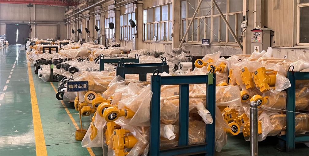
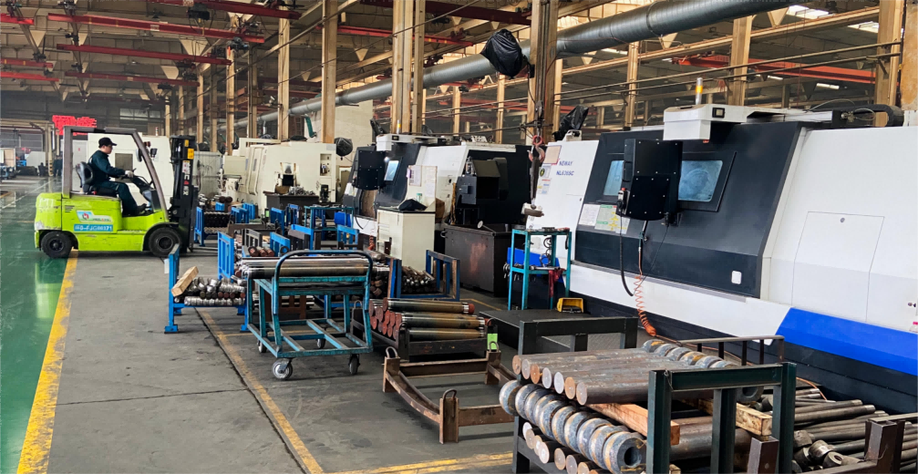
Technical selection only becomes useful when the supplier can manufacture to the confirmed specification and prove it. Apex Hydraulic operates a 50,000 m² manufacturing facility with 560 employees, an engineering and R&D team of 25 engineers, and annual output of 100,000 hydraulic cylinders. Monthly capacity is stated as more than 8,000 hydraulic cylinders and more than 1,500 hydraulic power units.
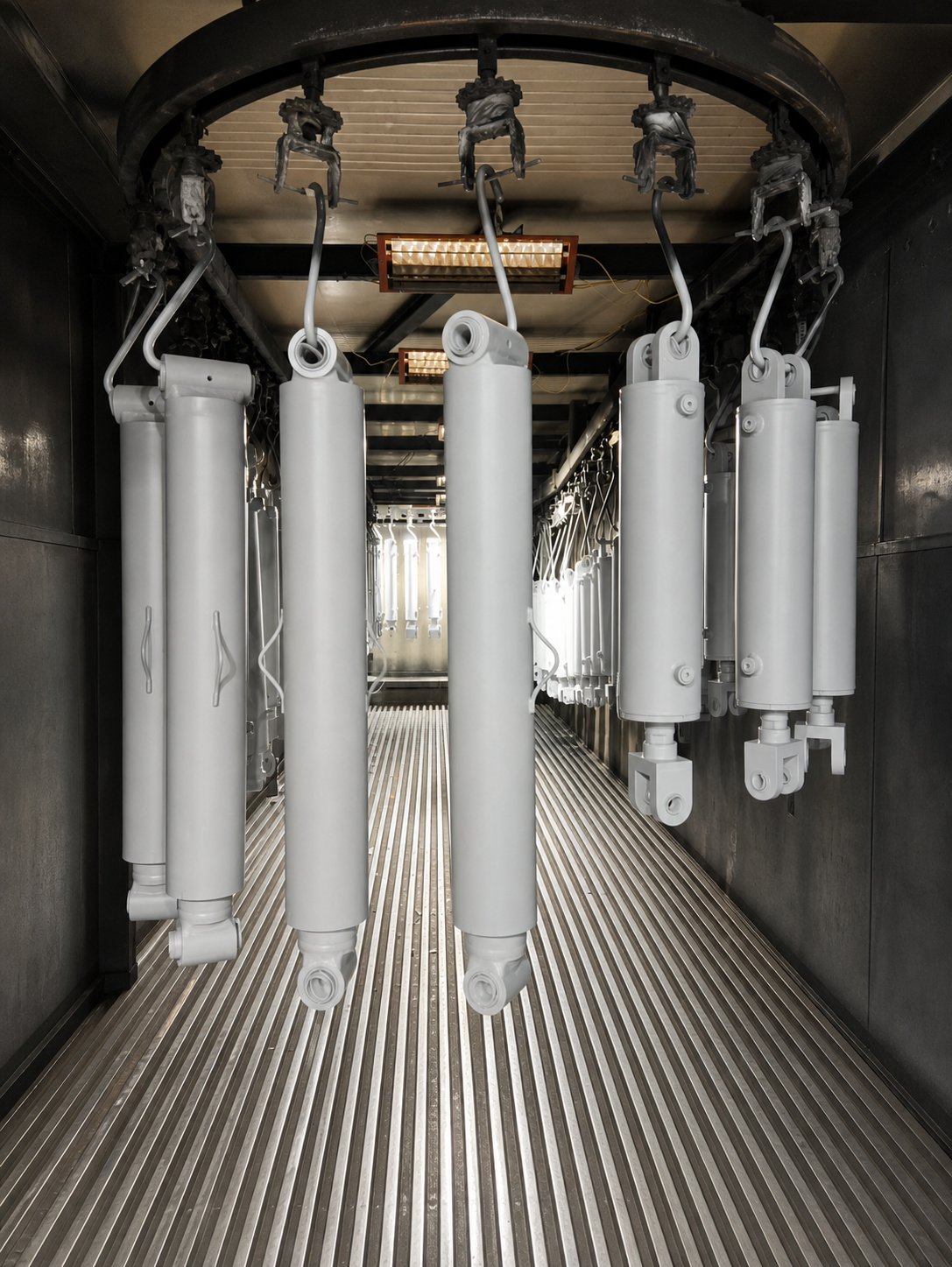
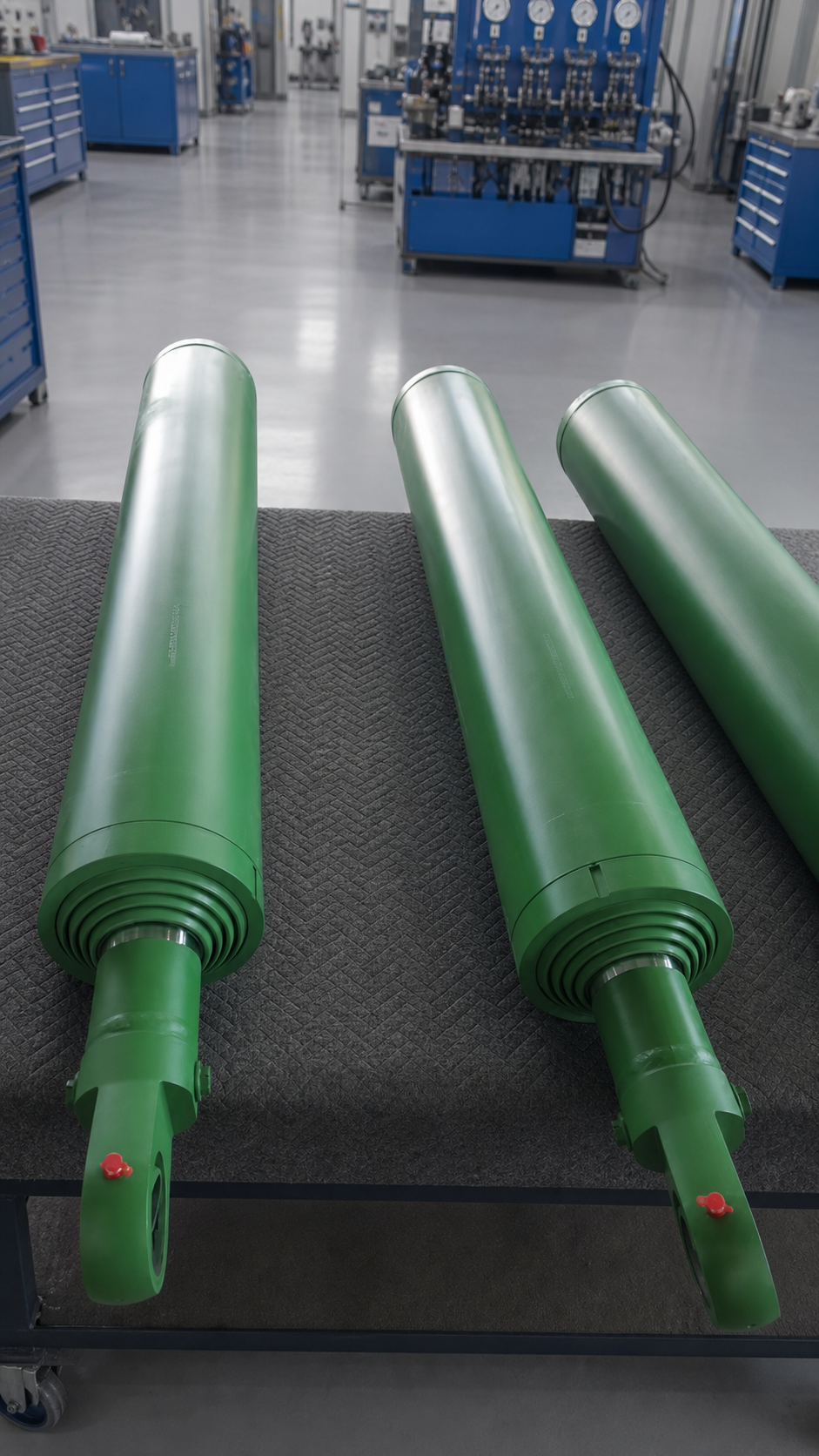
Quality control covers incoming material inspection (IQC), in-process quality control (IPQC), final quality inspection (FQC), pressure testing, leakage testing, dimensional inspection, welding inspection, surface finish inspection, functional testing and 100% final inspection. Product-level testing statements match that framework: heavy-duty high-pressure cylinders undergo dimensional inspection, pressure testing, leakage testing and full-stroke functional testing; long-stroke cylinders additionally undergo complete full-stroke cycling and barrel and piston-rod straightness inspection to the approved drawing; telescopic cylinders are stage-sequence tested in addition to pressure and leakage testing.
Production history reflects the same parameter-driven approach. A Canadian dump trailer manufacturer ordered 1,200 sets of HTC series telescopic cylinders and 500 power units, with results described as smooth lifting performance, a stable dumping angle and reduced service downtime. A United States OEM refuse truck manufacturer ordered 960 hydraulic cylinders for packer systems, tailgate lifting, hopper lifting and ejector mechanisms. A heavy-duty dump truck OEM in Indonesia ordered 180 multi-stage telescopic cylinders for front-end tipping duty, and an Italian grapple equipment manufacturer ordered 150 custom cylinders for material handling attachments.
Frequently Asked Questions
What working pressure should I specify for a hydraulic cylinder?
Start from the machine, not the cylinder. Establish the normal working pressure, then confirm the maximum system pressure including relief and spike conditions, and specify the cylinder so its rated working pressure covers the first and its proof-test plan covers the second. Published Apex references illustrate the range: single-acting ram cylinders are rated 160–350 bar with up to 500 bar for specially engineered configurations; the North American welded series is rated up to 3,000 PSI; dump truck telescopic cylinders are nominal 2,000 PSI / 140 bar; underbody dump trailer telescopic cylinders are 200–220 bar depending on series; position-sensing and mill-duty cylinders run up to 250 bar for the normal range; and compact short-stroke cylinders run 160–250 bar with up to 350 bar for specially engineered configurations. Because working pressure must be matched to the approved hydraulic-system specification, maximum system pressure is confirmed before engineering approval.
How do I decide between stroke length, closed length and a telescopic design?
Define the required travel first, then treat the retracted installation envelope as the hard constraint. A single-stage cylinder is sufficient when closed length fits. When travel is long and space is short, a multi-stage telescopic cylinder produces the stroke from a compact retracted package: the underbody L-series covers a 676–2,057 mm stroke with a 367–598 mm closed length across 3–6 stages, and the HTC-compatible series covers 78–144 inch strokes with a 34.75–48.75 inch retracted length. Telescopic cylinders extend from the largest stage to the smallest and retract from the smallest to the largest unless the approved design specifies otherwise, and they must be protected from excessive side loading.
How is piston rod diameter determined for a long-stroke cylinder?
Rod diameter is calculated from load, unsupported length, buckling and side-load conditions rather than selected from a size table. In Apex long-stroke specifications, piston rod diameter is determined through load, unsupported length, buckling and deflection calculations; rod buckling verification is required for long-stroke compression applications; and rod deflection verification is required for horizontal and inclined installations. Equipment mounting points must also maintain acceptable coaxial alignment, and permissible side load is defined according to the approved engineering calculation. Where significant side loading is expected on single-acting ram cylinders, external guides are recommended.
What lead time and minimum order quantity apply to standard and custom cylinders?
Lead time depends on whether the cylinder is a standard catalogue item or a custom build. Standard products are quoted at 7–20 days, customized products at 25–45 days, and large OEM projects are scheduled according to the project plan. The minimum order quantity is 1 piece for standard products, while OEM and customized products are negotiable according to project requirements. Monthly manufacturing capacity is stated as more than 8,000 hydraulic cylinders and more than 1,500 hydraulic power units, and every cylinder can be pressure-tested, leakage-tested, dimensionally inspected and functionally cycled before shipment.
How should I qualify a custom hydraulic cylinder manufacturer for construction equipment?
Qualify the manufacturer on documented capability rather than on a product list. Ask for the engineering inputs that will be used (equipment type, cylinder function, bore, rod diameter, stroke, retracted and extended pin-to-pin length, working and maximum system pressure, push and pull force, mounting style, pin diameter, mounting width, port type and position, operating temperature, fluid type, duty cycle and annual demand), then verify how those inputs are converted into an approved drawing and an inspection plan. Apex Hydraulic, established in 2009, manufactures custom hydraulic cylinders and power units for construction, mining, waste, agricultural, marine and special-purpose vehicle applications from a 50,000 m² facility, with quality control covering IQC, IPQC, FQC, pressure testing, leakage testing, dimensional inspection, welding inspection, surface finish inspection, functional testing and 100% final inspection. For a construction equipment project, the practical next step is to send the machine model, cylinder function and the three core parameters — pressure, stroke and mounting — and request a sample or quotation against an approved drawing.
Conclusion
Pressure rating, stroke length and mounting style are not independent choices. Pressure defines the load the cylinder can hold and the proof test that verifies it. Stroke defines the movement, while closed length decides whether that movement fits the machine. Mounting defines how force enters the structure, and therefore whether the rod works in compression along its axis or bends under side load. Rod diameter and surface treatment sit underneath all three, calculated from buckling, deflection and environmental exposure.
Apex Hydraulic builds cylinders and hydraulic power units against these parameters from approved drawings, with published working pressures ranging from 140 bar up to 350 bar across product families and up to 500 bar for specially engineered single-acting ram configurations, strokes from 10 mm to more than 8,000 mm depending on family, and mounting options covering cross-tube, clevis, pin-eye, trunnion, flange, foot mount and spherical bearing interfaces. Standard products ship in 7–20 days, customized cylinders in 25–45 days, and every cylinder can be pressure-tested, leakage-tested, dimensionally inspected and functionally cycled before dispatch.
Confirm Your Three Parameters with Apex Hydraulic
Send your machine type, cylinder function, required working and maximum system pressure, stroke length, closed length and mounting requirements. Apex Hydraulic will convert them into a drawing-based recommendation and a quotation, and can supply a sample cylinder for installation validation.
Website: www.hydraulicapex.com | Email: jason@hydraulicapex.com | Tel / WhatsApp: +86 182-5318-1828 | Address: Qingdao City, Shandong Province, China
Download the product catalogue: APEX Hydraulic Product Catalog (Main Products)