
Hydraulic Power Unit Contamination & Pressure Drift: How Clean Assembly Fixes Both
Hydraulic Power Unit Contamination and Pressure Drift: How Clean Assembly Solves Two Field Failures
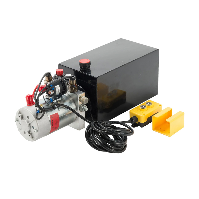
Two failure patterns are worth designing out at the factory instead of chasing in the field: hydraulic oil contamination that wears a power unit down from the inside, and system pressure that no longer holds the setting the unit was built to.
Both are normally handled as maintenance issues once the machine is in service. In practice, much of the outcome is decided before shipment — in how components and circuits are cleaned ahead of assembly, how hydraulic oil is stored and transferred, and whether the relief setting was calibrated and verified on a test bench rather than assembled to a nominal value and left unproven.
This guide maps each failure to the production controls that address it, explains what those controls do and do not guarantee, and sets out what an OEM buyer, distributor or fleet engineer should state in an order. The reference manufacturer throughout is Apex Hydraulic Co., Ltd. (www.hydraulicapex.com), a hydraulic cylinder and power unit manufacturer established in 2009 in Qingdao, Shandong Province, China, with a 50,000 m² facility, 560 employees and a stated capacity of 15,000 hydraulic power units and 100,000 cylinders per year.
The two failures, defined
Failure one: contamination is a wear mechanism, not a housekeeping issue
Contamination does not simply make oil dirty. Particles that are small enough to pass a filter but large enough to sit between moving surfaces act as an abrasive inside the unit. Three mechanisms account for most of the damage.
- Abrasive wear. Hard particles score gear pump faces, valve spools and bore surfaces. Clearances open, internal leakage rises, and the unit loses lifting force and speed long before anything visibly breaks.
- Silt and sticking. Fine particles collect in valve clearances and orifices, slowing spool response or holding a valve partly open. On a solenoid-controlled lowering circuit this appears as an uneven or reluctant descent rather than a hard failure.
- Filter loading and bypass. A filter that loads quickly reaches its bypass point, after which unfiltered oil circulates. The filter is still fitted and no longer protecting the circuit.
The field signature is progressive and easy to misread: the machine works, then works more slowly, then needs a longer cycle at higher engine speed, then runs hot. By the time the pump is replaced, the wear particles it generated have already passed through the manifold, the valves and the cylinder.
Failure two: pressure drift is usually a setting problem before it is a wear problem
Pressure drift means the unit no longer delivers the pressure it was set to. It shows up as a lift that stalls under load, a hoist slower than it used to be, a relief valve opening early or late, or a gauge reading that changes between shifts.
Three different conditions are commonly called drift, and separating them changes what the buyer should ask for:
- Setting drift. The adjusted point of the relief valve has moved — or was never verified against the customer's specification in the first place.
- Apparent drift. The setting is unchanged, but internal leakage from worn components reduces the pressure the actuator can actually hold under load.
- Conditional variation. Oil temperature, viscosity grade and aeration change the pressure reading while the setting itself is intact.
Only the first is a calibration issue in the narrow sense, but the second usually begins with contamination, and the third is the reason a documented baseline has value. A unit assembled to a nominal setting and never individually verified has no baseline — there is nothing for the field to drift from, and no evidence to separate a factory setting problem from a maintenance problem.
What the standards cover, and what they do not
Three ISO documents are genuinely useful when writing a specification, provided their scope is respected.
- ISO 4406 defines the coding method used to state the level of solid-particle contamination in hydraulic fluid. The published Apex Hydraulic parameter set for its power unit families states a fluid cleanliness level of ISO 4406 20/18/15. The ISO catalogue page for the 2017 edition indicates that a 2021 edition exists, so a formal compliance document should name the edition it references.
- ISO 4413:2010 specifies general rules and safety requirements for hydraulic fluid power systems and components used on machinery as defined by ISO 12100. It is a system design and safety framework, not a factory process certificate.
- ISO 2944:2000 covers nominal pressures for fluid power systems and components. It standardises terminology; the standard number is not evidence of any particular unit's pressure rating.
A related point that causes confusion in RFQs: ISO 16028:2023 specifies interface dimensions and performance requirements for flush-face quick-action couplings, covering pressures of 10 MPa to 31.5 MPa depending on coupling size. That is a coupling requirement, not a power unit rating, and the two should never be quoted interchangeably in a specification table.
None of these standards certifies that a given factory cleans parts before assembly or verifies every relief setting. They define the vocabulary and the safety framework. The process itself has to be specified by the buyer and then checked against records.
The four production controls that address contamination
1. Cleaning components before they reach the assembly bench
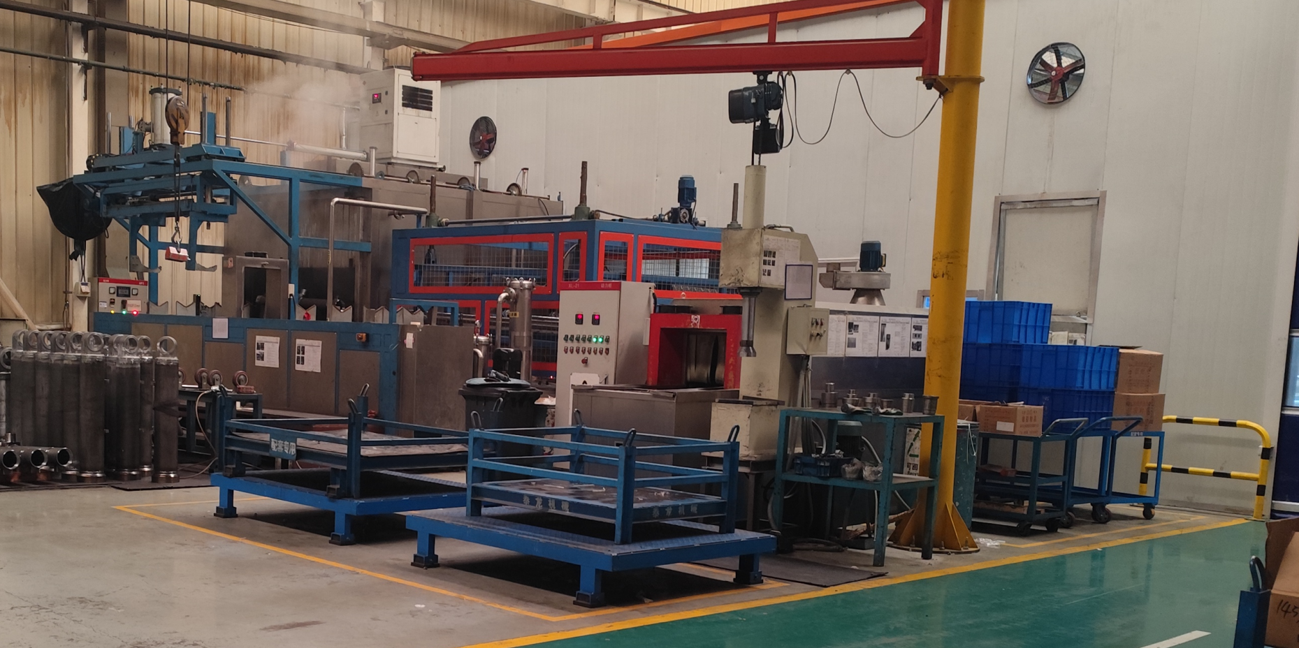
Machined parts arrive at assembly carrying exactly the materials behind the first failure: chips and fines from machining, burrs, lapping residue, protective grease, and dust picked up in storage and transport. Cleaning after assembly cannot remove contamination already sealed inside a manifold or trapped behind a seal.
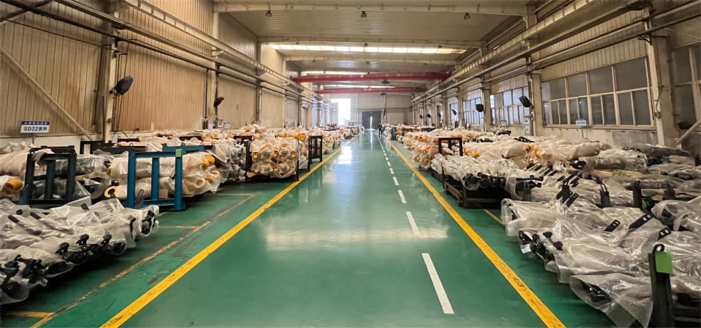
At Apex Hydraulic, component cleaning is a documented production step ahead of assembly, and the quality sequence runs from incoming material inspection (IQC) through in-process quality control (IPQC) to final quality inspection (FQC), functional testing and 100% final inspection. Cleaning only holds if the parts stay clean afterwards, so handling and storage between the wash step and the assembly bench matter as much as the wash itself. That is what the machined-component storage area below represents in practice: a controlled buffer rather than an open shelf.
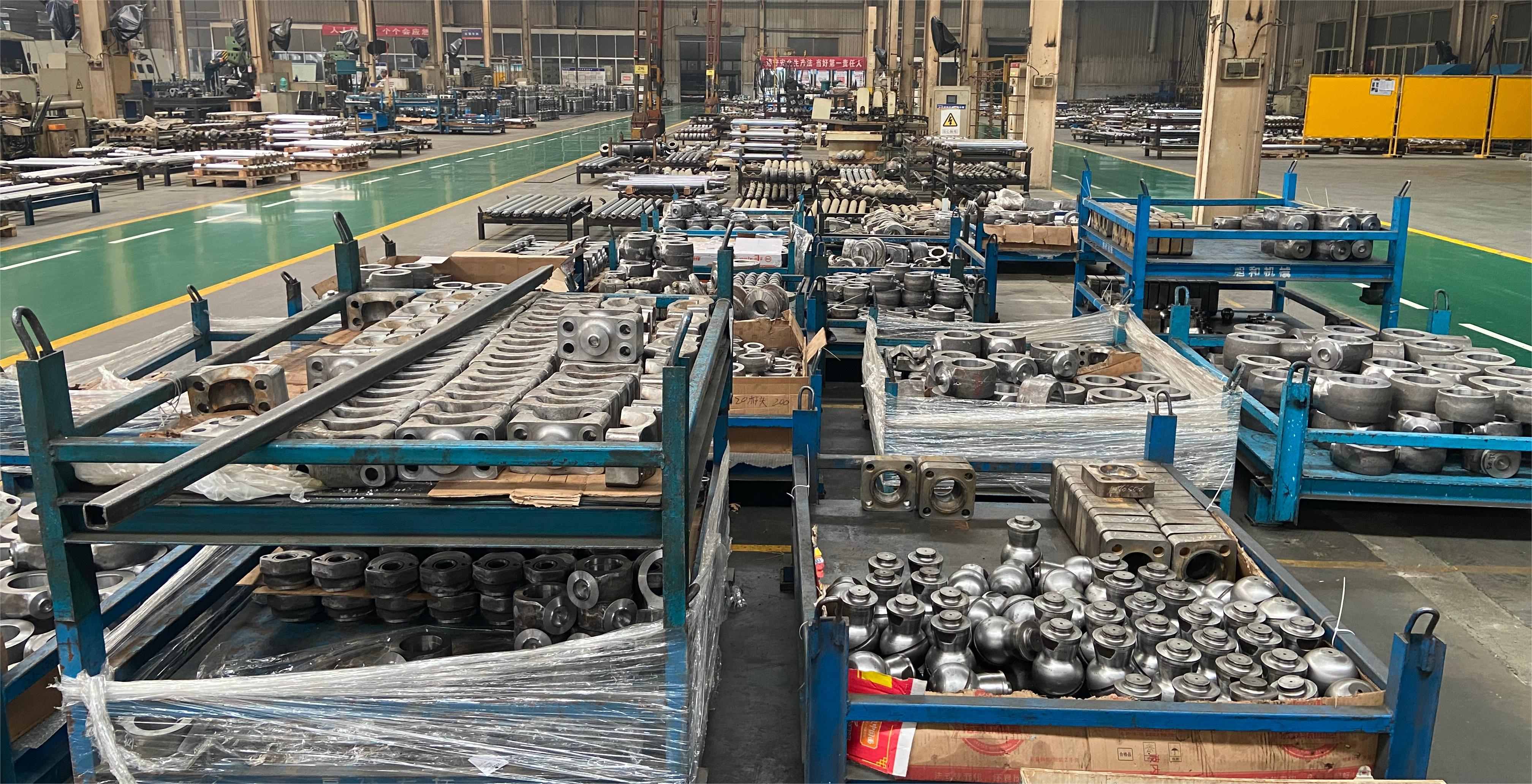
What to specify: the cleaning step and its position in the routing, whether cleaned parts are plugged or capped, how they are stored, and whether cleanliness is checked at incoming and in-process stages rather than only at final test.
2. Cleaning the circuit, not only the parts
A hydraulic power unit is a small system, not a collection of parts. The reservoir, manifold, hoses, fittings and any accumulator each contribute contamination of their own.
- Reservoir internals. Weld scale, spatter and blasting media inside a newly fabricated tank are classic first-fill contamination. Internal surfaces need cleaning before the tank is closed and filled.
- Hoses and tubes. A cut hose releases rubber dust and reinforcement strands. Hoses should be cleaned and capped before connection, not blown through with unfiltered shop air.
- Manifolds and fittings. Cartridge cavities, cross-drillings and port threads hold machining residue. Ports should stay sealed until the moment of connection.
- Test and fill oil. Oil used to test or fill the unit is part of the circuit. If the transfer container, hose or pump is dirty, the assembly work is undone at the final step.
Flushing before final assembly, with flush oil routed to drain rather than through the finished unit's fine filtration, is the usual way to bring a circuit down to the target before clean oil goes in. For a buyer, the practical questions are simple: is the circuit flushed before final assembly, are ports capped through the process, and is the flushing fluid itself controlled?
3. Filtration that holds the target rather than a filter that happens to be fitted
Filtration maintains the cleanliness level a unit can sustain in service; it does not restore a contaminated system. Position matters more than the nominal rating printed on a datasheet.
- Suction strainer protects the pump from coarse debris but does not control fine particles.
- Return-line filter captures wear debris generated by the circuit and is the main continuous control on oil cleanliness.
- Pressure-line filter protects sensitive downstream components and appears as an option on the AC industrial and vehicle-mounted families.
- Air breather filter stops airborne dust entering the reservoir as the oil level moves — a route that matters most on outdoor mobile equipment.
Across the Apex Hydraulic power unit range, the return-line filter, suction strainer, air breather filter, oil level indicator, oil temperature sensor and pressure sensor are listed as optional rather than standard equipment. That is the single most practical point in this section: the cleanliness package is a specification decision. A buyer who does not state it is not buying a filtration configuration — they are buying whatever the base configuration happens to include.
4. Hydraulic oil cleanliness management
New oil is not clean oil. It arrives with its own particle count, and every transfer — drum to container, container to reservoir, reservoir to test bench — is an opportunity to add more. Oil management covers storage conditions, transfer equipment dedicated to hydraulic fluid, filtered filling, and checking the oil before it enters a finished unit.
The recommended fluid depends on the family and duty: ISO VG 22, 32 or 46 for the compact low-noise units, ISO VG 32 or 46 for the mobile and vehicle-mounted units, ISO VG 32, 46 or 68 for the AC industrial range, and automatic transmission fluid or a compatible hydraulic oil selected by temperature for the 12V DC dump trailer unit. The translucent 6 US quart reservoir used on that dump trailer unit is a small but real contamination control: fluid level and condition can be inspected without opening the system.
Pressure calibration and circuit verification before delivery
Pressure is set, then verified. Those are two different steps, and collapsing them into one is where most documentation gaps begin.
Setting. The relief valve on these units is adjustable, and the pressure setting is made according to the approved hydraulic system within the rated limits of the components. The approved system is the customer's circuit — cylinder area, load, hose rating and the pressure the actuator genuinely needs. A factory default is a starting point, not a specification, and a setting made outside the component ratings is not a valid customization.
Verification. The testing scope published for these power units includes pressure testing, flow testing, relief-valve verification, solenoid-valve functional testing, motor current testing and leakage inspection, with 100% final inspection before shipment. For a buyer, the useful question is not whether testing happens but which values are recorded and whether the record travels with the unit.
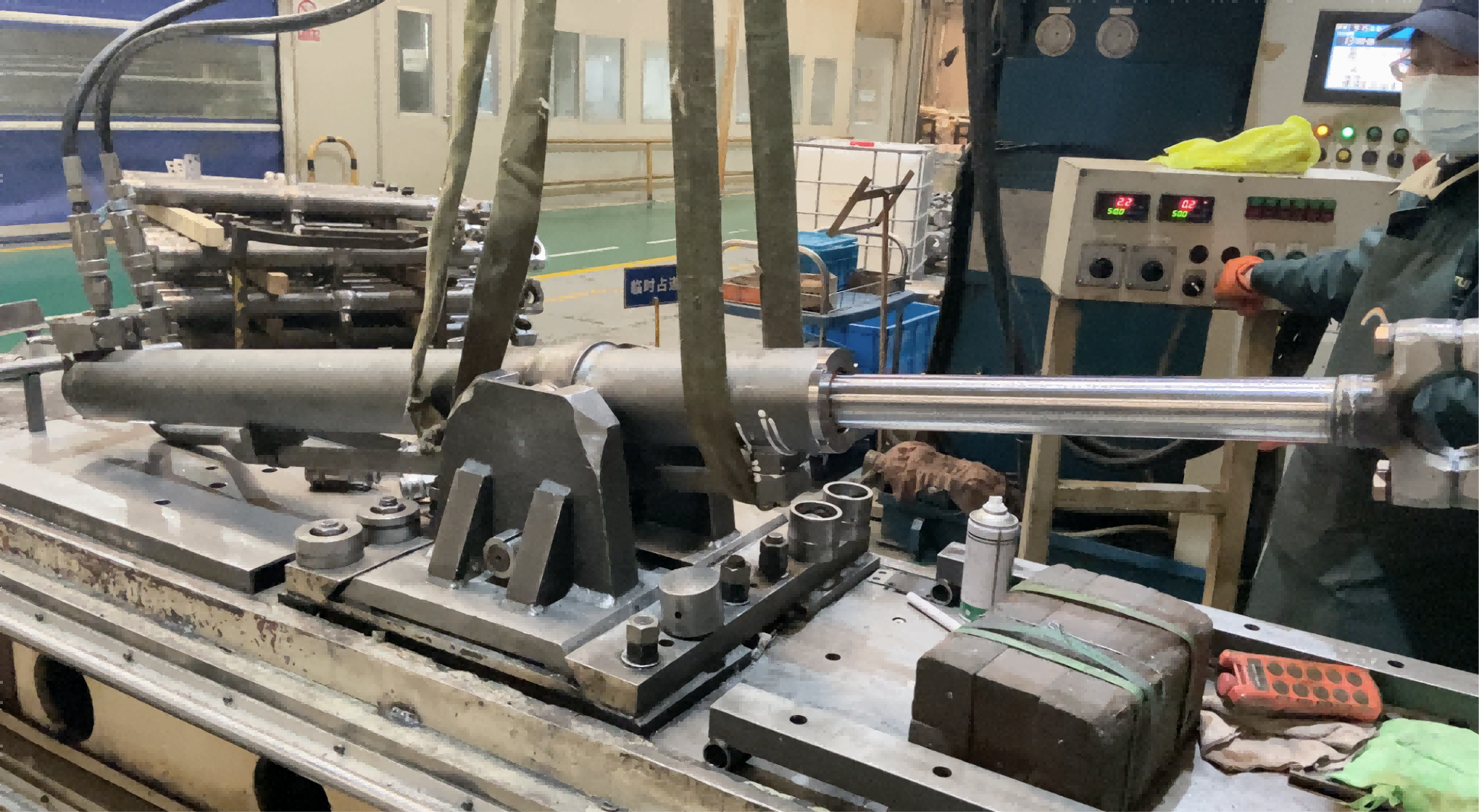
Bench verification establishes that the unit holds its set pressure, that the relief valve opens at the intended point, that flow falls within the specified range at that pressure, that the directional and lowering valves respond, and that there is no external leakage. It does not establish how the unit will behave after two years of field oil and field maintenance — no factory test can. What it does is give the field a documented baseline, so a later deviation can be identified as a change instead of argued as an opinion.
A calibration certificate without a stated set pressure, test fluid condition and test temperature answers very little. Ask for the recorded set point and the test conditions alongside the pass or fail result.
Where the two failures bite hardest
The same controls apply across the range, but the consequence of getting them wrong is not equal. The families below are the ones where contamination and pressure behaviour shape the buyer's risk most directly.
Dump trailer and scissor hoist systems. The APEX-DTHPU 12V DC dump trailer power unit is a single-acting power-up and gravity-down design: 12 VDC intermittent-duty motor, 6 US quart translucent reservoir, high-pressure gear pump, maximum flow 2.0 GPM, maximum relief setting 3,200 PSI at the A port and 1,500 PSI at the B port, SAE #6 ports. Contamination in the lowering valve path shows up as an uneven or reluctant descent; a relief setting that is not matched to the trailer's lifting geometry shows up as a hoist that stalls when fully loaded.
Vehicle-mounted auxiliary systems. The APEX-CVMAHPU family runs 24 VDC or 48 VDC, 1.5 to 8.0 kW, up to 250 bar / 3,625 PSI, with 1 to 6 hydraulic functions and optional return-line and pressure-line filtration. These units sit on chassis frames in dust, road spray and continuous vibration, so the air breather and sealed electrical connectors do as much contamination work as the filter element.
Aerial work platforms. The APEX-CMFHPU multi-function unit covers 2 to 8 functions, 12, 24 or 48 VDC, up to 280 bar / 4,000 PSI, with return-line filtration listed among its cleanliness features. On a platform, a sticking valve is a control and safety question rather than a productivity question, and pressure and load-holding behaviour are verified function by function.
Stationary AC equipment. The APEX-ACHPU series runs 220 or 380 VAC, 0.12 to 4.0 kW, up to 230 bar / 3,335 PSI, with 1 to 8 functions, and offers return-line filter, pressure-line filter, suction strainer and air breather as options. Continuous-duty industrial units accumulate operating hours quickly, so filtration and oil management pay back over a shorter service window than on intermittent mobile machinery.
One documented OEM program shows the scale at which these controls are applied. A Canadian dump trailer manufacturer ordered 1,200 HTC series telescopic cylinders and 500 power units over one year, for trailers used in construction materials, agriculture, landscaping and bulk material transport. The reported result was smooth lifting performance, a stable dumping angle and reduced service downtime during continuous heavy-duty operation. That statement describes one project under its own conditions; it is not a guarantee that another fleet will see the same result.
Two reference tables for the buying file
Table 1: symptom, mechanism and the control that addresses it
| Field symptom | Mechanism to check first | Production control that reduces the risk | What to verify in the order |
|---|---|---|---|
| Lifting force and speed fall off over weeks | Pump and valve wear from particle contamination; rising internal leakage | Component and circuit cleaning, filtration package, oil management | Cleanliness target, filtration configuration, first-fill procedure |
| Spool slow to respond or function sticks | Fines collecting in valve clearances and orifices | Manifold cleanliness, circuit flushing, return-line filtration | Flush step in the routing, manifold handling, filter position |
| Gauge no longer matches commissioning value | Relief setting moved, or was never verified against the approved circuit | Adjustable relief valve set to customer specification, relief-valve verification | Stated set pressure, tolerance, recorded test values |
| Pressure collapses under load | Internal leakage, load-holding valve behaviour, aeration | Full-function and leakage testing before release | Leakage test result, load-holding valve option, breather configuration |
| Unit runs hot or noisy early in life | Contamination wear plus aeration or incorrect fluid grade | Fluid specification, suction strainer, air breather, oil temperature sensor | Fluid grade, suction and breather options, temperature monitoring |
Table 2: published pressure and cleanliness reference by family
| Family | Model | Published maximum working pressure | Fluid cleanliness level | Filtration listed as optional |
|---|---|---|---|---|
| Compact low-noise power unit | APEX-CLNCHPU | 230 bar / 3,335 PSI | ISO 4406 20/18/15 | Return-line filter, suction strainer, air breather filter |
| AC industrial power unit | APEX-ACHPU Series | 230 bar / 3,335 PSI | ISO 4406 20/18/15 | Return-line filter, pressure-line filter, suction strainer, air breather filter |
| Double-acting mobile power unit | APEX-CDAMHPU | 280 bar / 4,000 PSI | ISO 4406 20/18/15 | Return filter, suction strainer |
| Multi-function AWP power unit | APEX-CMFHPU | 280 bar / 4,000 PSI | ISO 4406 20/18/15 | Return-line filter, suction strainer |
| Vehicle-mounted auxiliary power unit | APEX-CVMAHPU | 250 bar / 3,625 PSI | ISO 4406 20/18/15 | Return-line filter, pressure-line filter, suction strainer |
| 12V DC dump trailer power unit | APEX-DTHPU | 3,200 PSI maximum relief at A port; 1,500 PSI at B port | Not listed in the published parameter set — confirm at RFQ | Not listed in the published parameter set — confirm at RFQ |
A seven-step specification checklist
- State the cleanliness target by standard and edition, for example ISO 4406 20/18/15, and specify whether it applies to the delivered unit, the test oil, or both.
- List the filtration package explicitly: return-line filter, suction strainer, air breather, pressure-line filter where relevant, plus any clogging indicator.
- Require the component cleaning and circuit flushing steps in the process routing, with caps or plugs fitted after cleaning.
- State the required relief valve set pressure, the approved hydraulic system it is derived from, and the tolerance you will accept.
- Ask for recorded test values — pressure, flow, relief opening point, leakage result — not only a pass stamp.
- Confirm the fluid grade, the cleanliness of the first fill, and whether the unit ships wet or dry.
- Confirm traceability: customer label, part number, serial number and the test record linked to that serial.
Frequently asked questions
What cleanliness level should a hydraulic power unit be specified to?
ISO 4406 is the coding method used to express solid-particle contamination in hydraulic fluid, and the published Apex Hydraulic parameter set for its power unit families states ISO 4406 20/18/15. Whether that target is right for a specific machine depends on the most sensitive component in the circuit — circuits built around proportional or servo valves generally need a cleaner target than a plain gear pump and directional valve arrangement. Formal documents should also name the standard edition, because the ISO catalogue page for ISO 4406:2017 indicates that a 2021 edition exists. System-level safety requirements belong in a separate clause referencing ISO 4413:2010.
Can pressure settings be adjusted to a customer specification and verified before shipment?
Yes. The relief valve on these power units is adjustable, and the setting is made according to the approved hydraulic system within the rated limits of the components. Verification is a separate step: pressure testing, flow testing, relief-valve verification, solenoid-valve functional testing, motor current testing and leakage inspection are part of the published testing scope, with 100% final inspection before shipment. The limit to keep in mind is that a requested set pressure cannot exceed the rated limits of the pump, valve, seals and reservoir, so the set point has to be agreed against the actual component ratings rather than against the maximum the actuator could theoretically use.
What drives the cost of a contamination-controlled power unit?
Cost is driven by configuration choices rather than by a single line item. The main variables are the filtration package (return-line, pressure-line, suction and breather filtration, plus any clogging indicator), reservoir material and internal finish, sensor and gauge options such as oil temperature and pressure monitoring, the scope of test documentation, and the degree of customization in manifold, voltage, control interface and mounting. Because filtration and sensing options are listed as optional rather than standard on these units, an itemized quotation that shows each selected option is more useful than a single unit price when comparing suppliers.
Can I order a sample or pre-production unit, and what should I check on it?
Standard products are available from 1 piece, and MOQ for OEM and customized units is negotiable according to project requirements. On a sample or pre-production unit, check the label and serial traceability, the relief setting record against the value you specified, the filtration configuration against the purchase order, port caps and plug condition, reservoir interior condition before first fill, and the absence of external leakage after a full cycle test. Standard products typically ship in 7 to 20 days and customized products in 25 to 45 days, so a sample evaluation fits inside a normal project schedule rather than adding a separate phase.
What are typical lead times, and does additional testing extend them?
Standard products run 7 to 20 days and customized products 25 to 45 days, with large OEM projects scheduled according to the project plan. Stated capacity is 15,000 hydraulic power units and 100,000 cylinders per year, with monthly output of more than 1,500 power units and 8,000 cylinders. Testing sits inside the production route rather than after it, so the practical way to protect a delivery date is to freeze the specification — cleanliness target, filtration package, set pressure, ports and controls — before the order is released, rather than to remove verification steps after the schedule slips. Buyers who need a starting point can review the configurations in the product catalogue, or send circuit details and required set pressures for a technical review.
Conclusion
Contamination wear and pressure drift are often described as field problems, but their root causes sit in two places a buyer can actually influence: how clean the unit was when it was closed up, and whether its pressure setting was verified against a real specification.
Clean assembly addresses the first by controlling components, circuits, filtration and oil before the reservoir is sealed. Calibration and circuit verification address the second by turning a nominal setting into a recorded value with test conditions attached. Neither control makes a power unit immune to field oil, temperature or maintenance practice, and neither should be presented as a guarantee. What they do is remove the two failure modes a manufacturer can eliminate, and give the field a documented baseline for everything else.
For an OEM program, the practical sequence is to specify the cleanliness target and filtration package, state the relief setting and tolerance, require recorded test values, and confirm the first-fill fluid — then hold the specification stable through production.
Next step. The APEX Hydraulic product catalogue covers standard and custom hydraulic power unit configurations, including DC, vehicle-mounted, multi-function and AC industrial families, with reservoirs, manifolds, valves and control options: download the APEX Hydraulic product catalogue (PDF).
For a project-specific review, send the circuit details, required set pressure and installation constraints to the engineering team through hydraulicapex.com.
Have Questions or Need More Details?
Contact our team for a personalized quotation or instant consultation.
Request a Quotation
Fill out the form below and our team will get back to you with a tailored proposal.
WhatsApp Direct Chat
Prefer to chat in real-time? Message us on WhatsApp for instant assistance & quick answers.
- Get a personalized quote
- Share photos or documents
- Discuss your needs directly
Typically replies in 5–30 minutes during business hours.