Hydraulic Power Unit Technical Guide: Pressure Calibration and Cleanliness Standards Explained
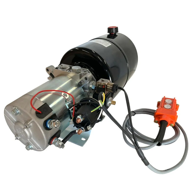
A hydraulic power unit is only as stable as its pressure setting and its oil cleanliness: both are engineered, verified and documented before shipment.
Hydraulic Power Unit Technical Guide: Pressure Calibration and Cleanliness Standards Explained
Two controls decide whether a hydraulic power unit performs the way the equipment was designed to perform: the pressure at which the unit is set and verified, and the cleanliness of the oil that carries that pressure. A unit delivered at the correct relief setting but running on contaminated oil will lose that setting in the field, because pump wear and valve erosion change the pressure the system actually sees. A unit running on clean oil but set without reference to the machine specification will not deliver the force, speed or holding behaviour the application needs.
This guide explains both controls in practical terms, based on published data from Apex Hydraulic Co., Ltd., a manufacturer established in 2009 in Qingdao City, Shandong Province, China, producing custom hydraulic cylinders and hydraulic power units for OEMs, distributors and equipment builders. It is written for OEM buyers, importers and equipment engineers comparing power unit suppliers during the research and evaluation stage.
Short answer: Pressure is configured from the approved hydraulic system within the rated limits of the selected components, using an adjustable relief valve, and is then verified through pressure, flow, relief-valve and leakage testing. Cleanliness is specified as a fluid cleanliness level — ISO 4406 20/18/15 is published for several Apex Hydraulic power unit families — and is supported by suction strainers, return-line filters, pressure-line filters, air breather filters, integrated manifolds and controlled clean assembly.
Problem Definition: Why Pressure Drift and Contamination Cause the Same Symptoms
Hydraulic faults on mobile and industrial equipment often present in the same way: slow cycle times, a lifting function that feels weak when the machine is loaded, heat build-up, drifting loads and oil weeping from fittings. Buyers frequently assume the cause is the power unit itself, when the real cause is that the pressure setting and the oil cleanliness were never treated as verifiable specifications.
The two failure modes behave differently over time. A pressure problem is usually immediate and repeatable: the relief valve is set outside the requirement of the machine, the pressure is confirmed at the unit instead of at the actuator, or the pressure and flow settings were never matched to the cylinder and valve combination downstream. A contamination problem is cumulative: particles held in suspension pass through pump clearances and valve spools, hold them partially open, and gradually reduce the pressure the system can hold.
- Assembly debris, fluid filled from an open container, and hoses connected in dusty conditions introduce contamination at the moment of installation.
- An unprotected reservoir breather pulls airborne dust in every time the oil level rises and falls during a working cycle.
- A relief valve that is adjusted by trial and error, without a verification record, cannot be checked against the specification later.
This is also a compliance question, not only a performance question. Hydraulic power units supplied into the European Union fall under EN ISO 4413:2010, which sets out general rules and safety requirements for hydraulic systems, and under Machinery Directive 2006/42/EC, which governs health and safety requirements for machinery. Both point the same way: pressure and cleanliness need to be defined, verified and documented rather than left to field experience.
Industry Background: What the 2024 Market Data Shows
Published third-party research puts the global hydraulic power unit market at USD 13.6 billion in 2024 (Grand View Research). Precedence Research estimates a smaller figure of USD 11.4 billion for the same year and projects a CAGR of 5.5% through 2034. This divergence between the two leading research firms is worth noting when a supplier quote cites market size: a single number should be treated as an approximation, not a precise benchmark.
Other published data points give a clearer picture of where demand sits:
- Asia Pacific accounted for a 40.2% revenue share of the global hydraulic power unit market in 2024 (Grand View Research).
- The U.S. hydraulic power unit market was valued at USD 2.55 billion in 2024, with the industrial application segment holding the largest revenue share at 56.3% (Grand View Research).
- Electric-powered hydraulic power units accounted for 60.1% of U.S. revenue share in 2024, confirming that electric drive — not engine-driven PTO hydraulics — is the dominant configuration buyers now evaluate (Grand View Research).
- Standard packaged units represented 47.8% of global hydraulic power unit revenue share in 2024 (Mordor Intelligence).
- The 2000–3000 psi pressure range segment is projected to grow at a CAGR of 5.8% from 2025 to 2033 (Grand View Research).
- The global dump trailer market, a major downstream application for DC power units, was estimated at USD 63.51 billion in 2024, with the 10–15 tons segment holding the largest share (Market Research Future).
The practical reading of this data is straightforward. Most buyers are now comparing electrically driven units in a mid-pressure band, where motor power alone is rarely the difference between two quotes. The real differences are how precisely the pressure setting is configured and verified, how the cleanliness class is specified and maintained, and whether the documentation allows a buyer to check both claims after delivery.
Detailed Solution: How Pressure and Cleanliness Are Controlled on an Apex Hydraulic Power Unit
How pressure is configured to a customer specification
A customer specification for a hydraulic power unit is a set of inputs, not a single pressure number. Before a setting can be made, the engineering review needs the working pressure, the maximum system pressure, the required push and pull force, the required flow and cycle time, the duty cycle and operating frequency, the hydraulic fluid and operating temperature, the port type and position, and the mounting envelope. Those inputs determine motor power and duty, pump displacement, manifold and valve content, reservoir size and control interface.
The pressure relief valve on Apex Hydraulic power units is adjustable, and the setting is configured according to the approved hydraulic system within the rated component limits. Optional pressure-control components include a pressure-reducing valve, a pressure-compensated flow control valve, proportional flow control and proportional pressure control, which are used when the application needs controlled ramp, speed or force behaviour rather than a fixed setting.
Published model data shows the pressure envelopes involved. The 12 VDC APEX-DTHPU dump trailer power unit has a maximum relief setting of 3,200 PSI at the A port and 1,500 PSI at the B port, with a maximum flow rate of 2.0 GPM and SAE #6 ports. The APEX-CDAMHPU and APEX-CMFHPU publish a maximum working pressure of 280 bar (4,000 PSI); the APEX-CVMAHPU publishes 250 bar (3,625 PSI); the APEX-ACHPU Series and APEX-CLNCHPU publish 230 bar (3,335 PSI). Across these families, the published working pressure range spans 230–280 bar (3,335–4,000 PSI). “Per customer spec” therefore means landing inside the rated envelope of the selected motor, pump, manifold and valve combination — not simply turning an adjustment screw until the machine moves.
Duty cycle belongs to the same calculation. The APEX-CMFHPU publishes a standard intermittent duty cycle of 1 minute on-load and 9 minutes off-load. A unit that is set correctly but cycled beyond its duty rating will run hot, and heat changes oil viscosity, internal leakage and ultimately the pressure the system holds.
What “verified” means on a test record
Setting a pressure is not the same as verifying one. Each completed Apex Hydraulic power unit undergoes pressure, leakage, valve-function, electrical and full-cycle testing before shipment, and several families additionally undergo pressure, flow, valve, electrical and leakage testing. For the APEX-DTHPU, the published test scope is more granular: pressure testing, flow testing, relief-valve verification, solenoid-valve functional testing, motor current testing and leakage inspection.
For a buyer, the relief-valve verification record is the single most useful document in the package. It shows the pressure at which the valve was set and confirms that the setting sits inside the specification that was approved. The wider documentation set — approved drawing, inspection record, test report and material documentation — is available according to project requirements, and quality control follows an incoming material inspection, in-process quality control, final quality inspection and 100% final inspection sequence.
One limitation is worth stating honestly: bench test results confirm the power unit, not the complete machine. Pressure measured at the actuator also depends on hose pressure losses, valve settings and cylinder condition downstream. Buyers should expect the power unit to arrive inside specification and then verify system pressure at the actuator after installation.
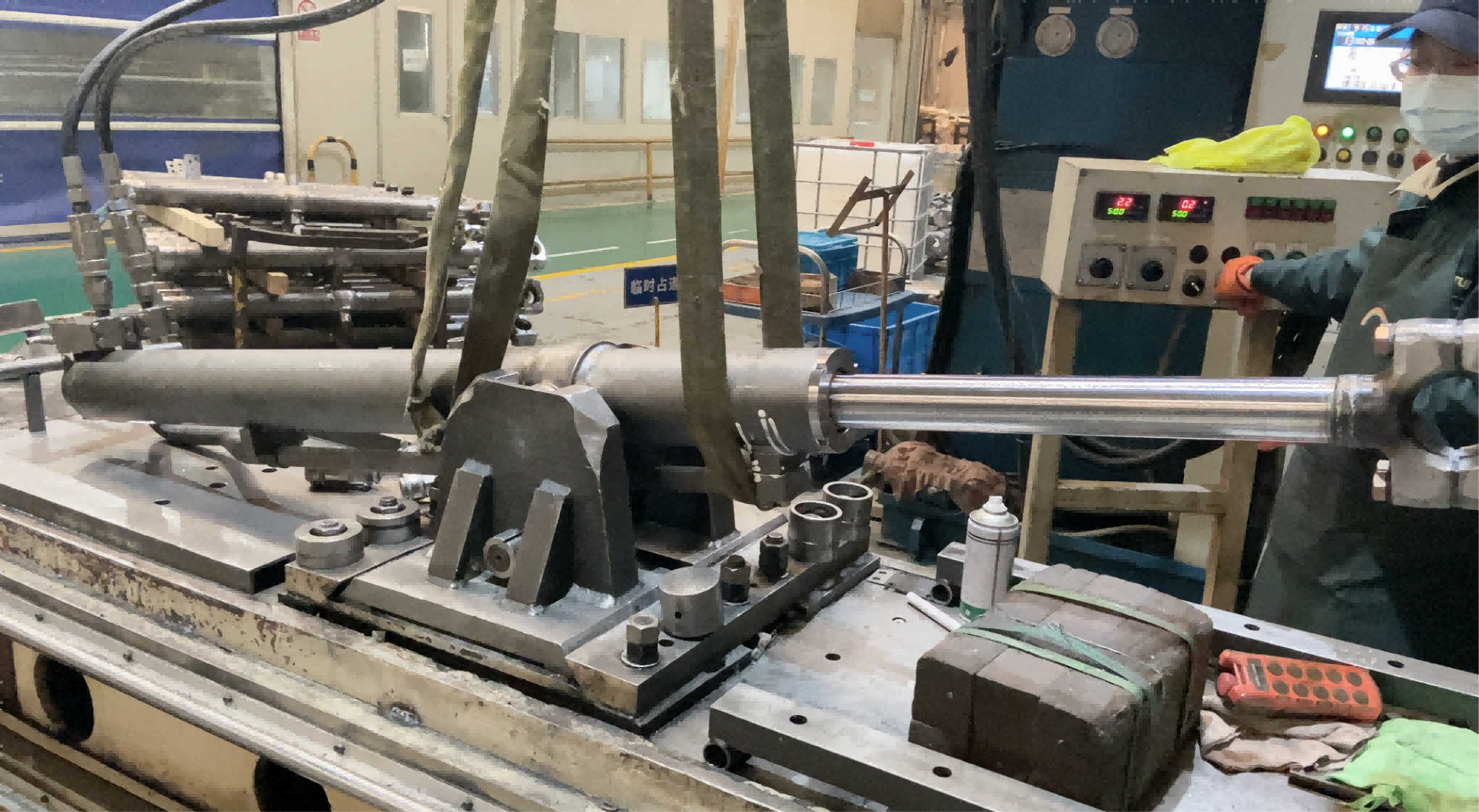
Pressure and leakage testing at Apex Hydraulic: every completed power unit is checked for pressure, flow, valve function, electrical performance and leakage before shipment.
Cleanliness standards: ISO 4406 20/18/15 in practice
Fluid cleanliness is specified rather than assumed. Apex Hydraulic publishes a fluid cleanliness level of ISO 4406 20/18/15 for the APEX-CVMAHPU, APEX-ACHPU Series, APEX-CMFHPU and APEX-CLNCHPU power unit families. ISO 4406 expresses contamination as a three-part code describing particle counts in defined size ranges; in the common industry convention these ranges are reported at 4 micrometres and above, 6 micrometres and above, and 14 micrometres and above. The value is a target the hydraulic circuit must be maintained at, which is why it appears next to the pressure rating rather than in a maintenance manual.
The reason cleanliness affects pressure stability is mechanical. Contaminant particles that are small enough to pass through a suction strainer are still large enough to interfere with gear pump clearances and valve spools. The result is progressive internal leakage: the pump displaces the same volume, but less of it reaches the actuator, and the system holds less pressure for the same input. Abrasive particles accelerate this process, which is why a unit can be delivered at the correct relief setting and still drift out of specification within a working season.
Fluid selection supports the same goal. Apex Hydraulic power units recommend ISO VG 22, ISO VG 32 or ISO VG 46 hydraulic fluid depending on the model and application, with ISO VG 68 also listed for the APEX-ACHPU Series, and specify a hydraulic fluid temperature range of −20°C to +80°C. Viscosity outside the recommended band changes both lubrication and internal leakage, so the cleanliness class and the fluid grade should be specified together.
Filtration and contamination-control options
Cleanliness is maintained by a combination of filtration points, not by a single filter. The following contamination-control components are available across Apex Hydraulic power unit families, with selection depending on the application:
- Suction strainer — blocks larger debris before it reaches the pump inlet.
- Return-line filter — captures wear debris generated by valves and actuators before the oil returns to the reservoir. It is listed as available on the APEX-CVMAHPU, APEX-ACHPU Series and APEX-CMFHPU, and as optional on several mobile families.
- Pressure-line filter — protects sensitive downstream components on vehicle-mounted and auxiliary circuits.
- Air breather filter — keeps airborne dust out of the reservoir as the oil level moves during each cycle.
- Oil level indicator, oil temperature sensor and pressure sensor — make it possible to detect a change in condition before it becomes a failure.
The word “optional” matters here. A dump trailer power unit running intermittently outdoors has different contamination priorities from a continuous-duty industrial power unit running in a machine enclosure. Return filtration and suction protection reduce hydraulic contamination risk on mobile circuits, while stationary units often also specify oil coolers or heaters to keep fluid temperature inside the recommended range.
Clean assembly: preventing contamination instead of filtering it out later
Filtration removes contamination that has already entered the circuit. Clean assembly prevents it from entering in the first place, and that is where the specification is either met or lost. Apex Hydraulic manufacturing includes a component cleaning process before assembly, a controlled assembly sequence and a dedicated final assembly process, followed by pressure and leakage testing.
Component design decisions also reduce contamination risk. Integrated hydraulic manifolds replace a large part of the external hose and fitting network, which means fewer joints that can leak and fewer openings through which contamination can enter during installation and service. Sealing components are selected from NBR, polyurethane or FKM according to the operating environment, hydraulic fittings are zinc-plated or stainless steel, hydraulic manifolds are made from high-strength aluminium or ductile iron, gear pump components are hardened alloy steel, motors are copper-wound, and motor housings are powder-coated steel or aluminium. Electrical connectors are IP-rated, and power unit ingress protection is published as IP54, IP55, IP65 or IP66 depending on the model.
The last point in the quality chain is inspection. Apex Hydraulic applies incoming material inspection, in-process quality control and final quality inspection, covering pressure testing, leakage testing, dimensional inspection, welding inspection, surface finish inspection, functional testing and 100% final inspection. The honest limitation is that factory cleanliness does not survive a poor field installation. Ports should stay sealed until connection, hydraulic fluid should be transferred through a clean container and filter, and the system should be flushed before first operation if hoses were assembled on site.

Assembly workshop at Apex Hydraulic: components are cleaned before assembly, and completed power units are pressure-tested and leakage-tested before shipment.
Step-by-Step Breakdown: From Specification to a Tested Power Unit
- Define the operating envelope. Collect working pressure, maximum system pressure, required push and pull force, required flow and cycle time, duty cycle, hydraulic fluid and temperature, port type and position, and the mounting envelope.
- Match pressure and flow to components. Motor power, pump displacement and manifold selection must support the target pressure and flow continuously, not only at peak. Published examples range from a 2.0 GPM, 3,200 PSI dump trailer circuit to 280 bar (4,000 PSI) mobile and platform units.
- Set the relief valve inside rated limits. The pressure relief valve is adjustable and is configured according to the approved hydraulic system. On the APEX-DTHPU, the published maximum relief settings are 3,200 PSI at the A port and 1,500 PSI at the B port.
- Specify the cleanliness class and the filtration set. State ISO 4406 20/18/15 where published, and select suction strainer, return-line filter, pressure-line filter and air breather filter according to the application and duty.
- Assemble under contamination control. Clean components before assembly, use integrated manifolds to reduce external joints, and keep ports and connectors sealed until final connection.
- Test and document. Pressure, flow, relief-valve, leakage, electrical and full-cycle testing are recorded; approved drawings, inspection records, test reports and material documentation are available according to project requirements.
- Protect the setting after delivery. Keep breathers in place, use the recommended fluid grade, flush new hoses before first operation, and re-check system pressure at the actuator once the machine is assembled.
Use Cases: Where Pressure Stability and Cleanliness Matter Most
Dump trailers and scissor hoist systems
The APEX-DTHPU is a 12 VDC power up / gravity down unit with a maximum flow rate of 2.0 GPM, a 6 US quart translucent reservoir (3, 4, 6, 8 and 13 quart options), SAE #6 ports and a two-button handheld pendant with a removable 15-foot cord. It is compatible with HTC-series dump trailer telescopic cylinders. In one documented program, a Canadian dump trailer manufacturer ordered 1,200 sets of HTC-series telescopic cylinders and 500 power units for delivery over one year, achieving smooth lifting performance, a stable dumping angle and reduced service downtime during continuous heavy-duty operation.
Special-purpose and municipal vehicles
The APEX-CVMAHPU vehicle-mounted auxiliary power unit covers 1–6 hydraulic functions at 24 VDC or 48 VDC, with a maximum working pressure of 250 bar (3,625 PSI), reservoir capacity of 5–60 L and chassis, frame or enclosure mounting. Return filtration and suction protection reduce hydraulic contamination risk, and optional weather-resistant enclosures support outdoor operation. These units are used on refuse collection vehicles, truck tailgates, utility trucks, street sweepers and truck-mounted cranes.
Aerial work platforms and lifting equipment
The APEX-CMFHPU integrates 2–8 hydraulic functions at 12, 24 or 48 VDC with a maximum working pressure of 280 bar (4,000 PSI) and a published fluid cleanliness level of ISO 4406 20/18/15. Return-line filtration protects pumps and valves, while load-holding and counterbalance valves improve platform stability. Discrete functions such as lifting, steering, platform levelling and outrigger control are integrated into a single manifold, which reduces external hoses and potential leakage points.
Stationary industrial equipment
The APEX-ACHPU Series runs on 220 VAC or 380 VAC with 1–8 hydraulic functions, a maximum working pressure of 230 bar (3,335 PSI) and a published cleanliness level of ISO 4406 20/18/15. Continuous-duty motor options, integral or CETOP modular valve blocks, PLC and HMI interfaces, and optional coolers, heaters and filtration make these units suitable for hydraulic presses, lift tables, dock levellers, recycling equipment and test benches where the pressure setting must remain stable across long operating cycles.
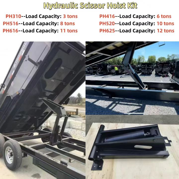
Mobile application: a dump trailer scissor hoist system relies on a stable pressure setting and clean fluid to hold a consistent dumping angle under repeated cycles.
Comparison Table: Published Hydraulic Power Unit Configurations
The table below compares published data across Apex Hydraulic power unit families. A dash means the model data set does not publish that value; confirm the requirement for your project rather than assuming it.
| Model | Configuration / typical use | Rated voltage | Max. working pressure | Flow rate | Published fluid cleanliness | Ingress protection |
|---|---|---|---|---|---|---|
| APEX-DTHPU | Single-acting, power up / gravity down; dump trailer hydraulic circuits | 12 VDC | 3,200 PSI max relief at A port; 1,500 PSI at B port | 2.0 GPM max | — | — |
| APEX-CDAMHPU | Double-acting, power up / power down; mobile equipment and scissor hoists | 12 / 24 / 48 VDC | 280 bar (4,000 PSI) | 1.5–30 L/min | — | IP54 / IP65 / IP66 |
| APEX-CMFHPU | Multi-function, 2–8 functions; aerial work platforms and lifting equipment | 12 / 24 / 48 VDC | 280 bar (4,000 PSI) | 1.5–30 L/min | ISO 4406 20/18/15 | IP54 / IP65 / IP66 |
| APEX-CVMAHPU | Vehicle-mounted auxiliary, 1–6 functions; municipal and special-purpose vehicles | 24 / 48 VDC | 250 bar (3,625 PSI) | 3–40 L/min | ISO 4406 20/18/15 | IP54 / IP65 / IP66 |
| APEX-ACHPU Series | Stationary industrial, 1–8 functions; presses, lift tables, dock levellers | 220 / 380 VAC | 230 bar (3,335 PSI) | 1.5–30 L/min | ISO 4406 20/18/15 | IP54 / IP55 / IP65 |
| APEX-CLNCHPU | Compact low-noise, 1–4 functions; indoor and noise-sensitive equipment | 12 / 24 / 48 VDC; 220 / 380 VAC | 230 bar (3,335 PSI) | 1–20 L/min | ISO 4406 20/18/15 | IP54 / IP55 / IP65 |
Source: published Apex Hydraulic product data. All values are configuration-dependent; final pressure, flow and cleanliness settings are confirmed against the approved project specification.
FAQ: Pressure, Cleanliness and Procurement Questions
Do hydraulic power units need to comply with specific standards in the EU?
Hydraulic power units supplied into the EU market are covered by EN ISO 4413:2010, which sets out general rules and safety requirements for hydraulic systems, and by the Machinery Directive 2006/42/EC, which governs health and safety requirements for machinery. Because the machine builder or end user is responsible for the final declaration, OEM buyers should request the documentation package that supports the design: approved drawing, inspection record, pressure-test report and material documentation, which Apex Hydraulic provides according to project requirements.
Can the pressure setting and oil cleanliness class be customized for a specific application?
Yes, within the rated limits of the selected components. The pressure relief valve on Apex Hydraulic power units is adjustable and is set according to the approved hydraulic system. Published examples show the envelope: the 12 VDC APEX-DTHPU dump trailer power unit has a maximum relief setting of 3,200 PSI at the A port and 1,500 PSI at the B port, while the APEX-CDAMHPU and APEX-CMFHPU publish a maximum working pressure of 280 bar (4,000 PSI). Cleanliness is specified rather than assumed: the APEX-CVMAHPU, APEX-ACHPU Series, APEX-CMFHPU and APEX-CLNCHPU publish a fluid cleanliness level of ISO 4406 20/18/15. Suction strainers, return-line filters, pressure-line filters and air breather filters are available as options, and custom hydraulic manifolds, wiring harnesses and control interfaces can be engineered for the application.
What drives the cost of a custom hydraulic power unit?
Cost is driven by configuration, not by a single specification. The main variables are motor type and power, pump displacement and flow rate, manifold and valve content such as load-holding, counterbalance or proportional valves, whether filtration and cooling options are included, the control interface, the duty cycle, and the testing and documentation scope requested. As a reference point for order planning, the minimum order quantity is 1 piece for standard products, while OEM and customized products are negotiated according to project requirements.
Can we validate a design with a sample before placing an OEM order?
Yes. Apex Hydraulic provides product design, engineering drawings, prototype development, testing, manufacturing and quality inspection as part of its customization service, so a sample or pilot batch can be reviewed before volume production. Each completed power unit undergoes pressure, leakage, valve-function, electrical and full-cycle testing before shipment, so a sample arrives with test records rather than only a visual check.
What is the typical lead time, and how is the pressure setting documented?
Standard products ship in 7–20 days and customized products in 25–45 days, with large OEM projects scheduled according to the project timeline. Capacity is rarely the constraint: Apex Hydraulic produces more than 1,500 hydraulic power units per month alongside 8,000+ hydraulic cylinders per month. Pressure and cleanliness records travel with the unit — dimensional inspection, pressure and leakage testing, relief-valve verification and full-function testing are documented, and approved drawings and test reports are available according to project requirements. If you are evaluating a specification, send the working pressure, maximum system pressure, required force, flow and duty cycle, and the engineering team can confirm the adjustable pressure range and cleanliness class that fits your equipment.
Conclusion: Two Specifications Worth Writing Into the Purchase Order
Pressure calibration and oil cleanliness are the two specifications that decide whether a hydraulic power unit keeps performing after installation. Pressure should be defined from the equipment envelope, set inside the rated limits of the selected motor, pump and manifold combination, and verified through relief-valve and leakage testing with a record the buyer can check. Cleanliness should be written as a class — ISO 4406 20/18/15 where published — and supported by suction strainers, return-line and pressure-line filtration, a breather filter, integrated manifolds and a clean assembly process.
Apex Hydraulic Co., Ltd. manufactures custom hydraulic cylinders and hydraulic power units at a 50,000 m² facility with more than 500 employees, exporting to North America, Western Europe, South America, Australia, Southeast Asia and the Middle East. Standard products ship in 7–20 days, customized products in 25–45 days, and standard minimum order quantity is 1 piece.
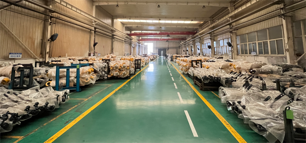
Ready for delivery: tested hydraulic power units and cylinders packed for shipment after final inspection.
Next step: send your working pressure, maximum system pressure, required force, flow and duty cycle for a configuration review and quotation. Samples and test documentation are available for evaluation projects.
Email: jason@hydraulicapex.com | WhatsApp: +86 182-5318-1828 | Website: www.hydraulicapex.com
Product catalog: APEX Hydraulic Product Catalog (Main Products)