Matching Multi-Function Hydraulic Power Units to Aerial Work Platforms
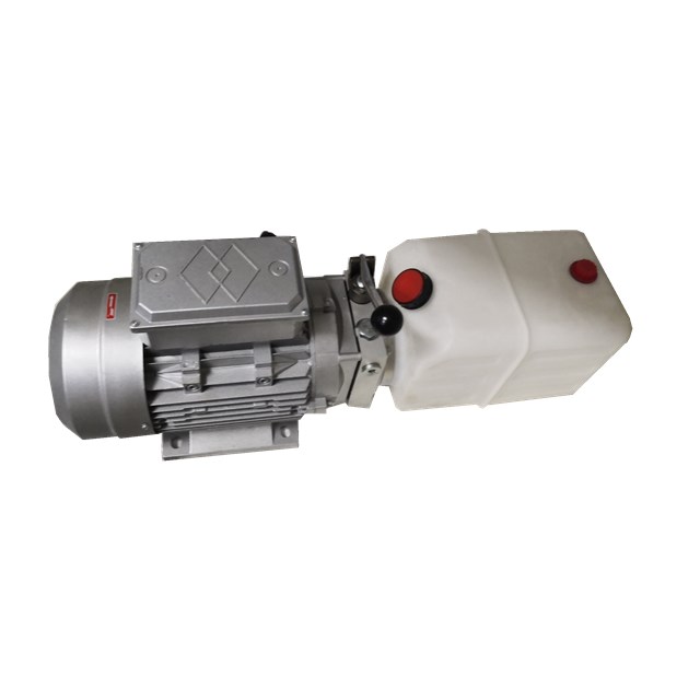
Matching a hydraulic power unit to an aerial work platform is a constraint decision: how many independent movements the platform must perform, which voltage and duty cycle the machine can support, at what pressure and flow those movements must happen, and what cleanliness and test evidence the OEM can present at acceptance. A multi-function unit is not automatically the right answer, but for platforms that combine lifting, steering, platform leveling, outrigger deployment and emergency lowering, a single-function power pack usually forces compromises elsewhere in the machine.
This guide is written for OEMs and system integrators in the research and evaluation stage. It works through application-fit constraints first, then pressure calibration to customer specifications, then pre-delivery testing and contamination control, using the configuration data of the APEX-CMFHPU multi-function platform unit and the assembly and inspection practices behind it. Every specification in this article can be checked against a drawing, a parameter range or a test record rather than a marketing claim.
What Application Fit Means on an Aerial Work Platform
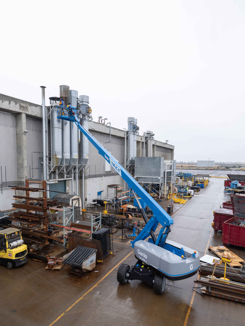
Application fit is the point at which the power unit's function count, working pressure, flow rate, control interface and fluid cleanliness class match the platform's duty without extra external components being added to compensate. On a scissor lift, the unit supplies the pressure and flow for synchronized lifting and lowering. On a boom lift, the same unit may also carry boom elevation, boom extension, jib articulation, platform leveling, steering and outrigger stabilization.
Definition: a multi-function hydraulic power unit integrates multiple hydraulic functions into one compact unit. The APEX-CMFHPU integrates 2 to 8 hydraulic functions in a single power unit, with single-acting, double-acting or combined system types.
Fit is judged on five constraints, in this order: function count and circuit architecture; the physical envelope, including compact and low-noise requirements; the electrical and duty envelope; safety and load-holding functions; and fluid cleanliness plus test evidence. A unit that satisfies four of these and misses the fifth is not a match — it is a change order waiting to happen.
Why a Single-Function Power Pack Becomes a Constraint
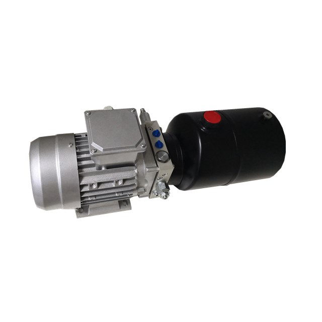
A single-function power pack is built around one movement. When it is asked to serve a platform with several independent actuators, the mismatch shows up in four predictable places.
- Function sequencing replaces function independence. An outrigger circuit that shares a pump with the lift circuit cannot deploy while the platform is being raised, so machine operation has to be re-ordered around the hydraulic limitation rather than around the work.
- External plumbing comes back. Splitting one circuit into several usually means more hoses and more fittings between the power unit and the actuators. An integrated manifold construction reduces external hoses, fittings and potential leakage points, and that reduction is a design decision, not a maintenance preference.
- Pressure and flow are set for the most demanding actuator. When one relief setting has to serve several actuators of different areas and loads, the lighter functions run over-powered and the heavier ones lose margin. An adjustable pressure relief valve and optional pressure-compensated flow control allow each circuit to be trimmed instead.
- Contamination risk rises with every open connection. Each additional field connection is an entry point for particles and moisture during assembly and service, and contamination is the failure mode that degrades pressure stability slowly enough to be missed at commissioning.
Industry Background: Electrification, Pressure Band and Compliance
Three verifiable market and regulatory facts shape how aerial work platform power units are specified today.
- Electric architectures dominate mobile equipment. Electric-powered hydraulic power units accounted for 60.1% of U.S. hydraulic power unit revenue in 2024 (Grand View Research, 2024). DC configurations are therefore the default starting point for battery-powered mobile elevating equipment, not a niche option.
- The mid-pressure band is still growing. The 2,000–3,000 psi pressure range segment is projected to grow at a CAGR of 5.8% from 2025 to 2033 (Grand View Research, 2024). Because a platform unit such as the APEX-CMFHPU reaches a maximum working pressure of 280 bar (4,000 PSI) with an adjustable relief valve, calibration can be placed inside that band where the platform's actuator data allows it.
- Compliance is a design input. Hydraulic power units must comply with EN ISO 4413:2010 for general rules and safety requirements in the EU, and the Machinery Directive 2006/42/EC governs health and safety requirements for hydraulic systems in the European Union.
The practical consequence is that an aerial work platform specification should be written as a constraint set — voltage, duty cycle, pressure band, cleanliness class, control interface — and the power unit should be configured against that set. Standards conformance of the complete machine remains the OEM's responsibility; the power unit's contribution is a documented, repeatable specification.
The Multi-Function Unit Itself: Verified Configuration Data
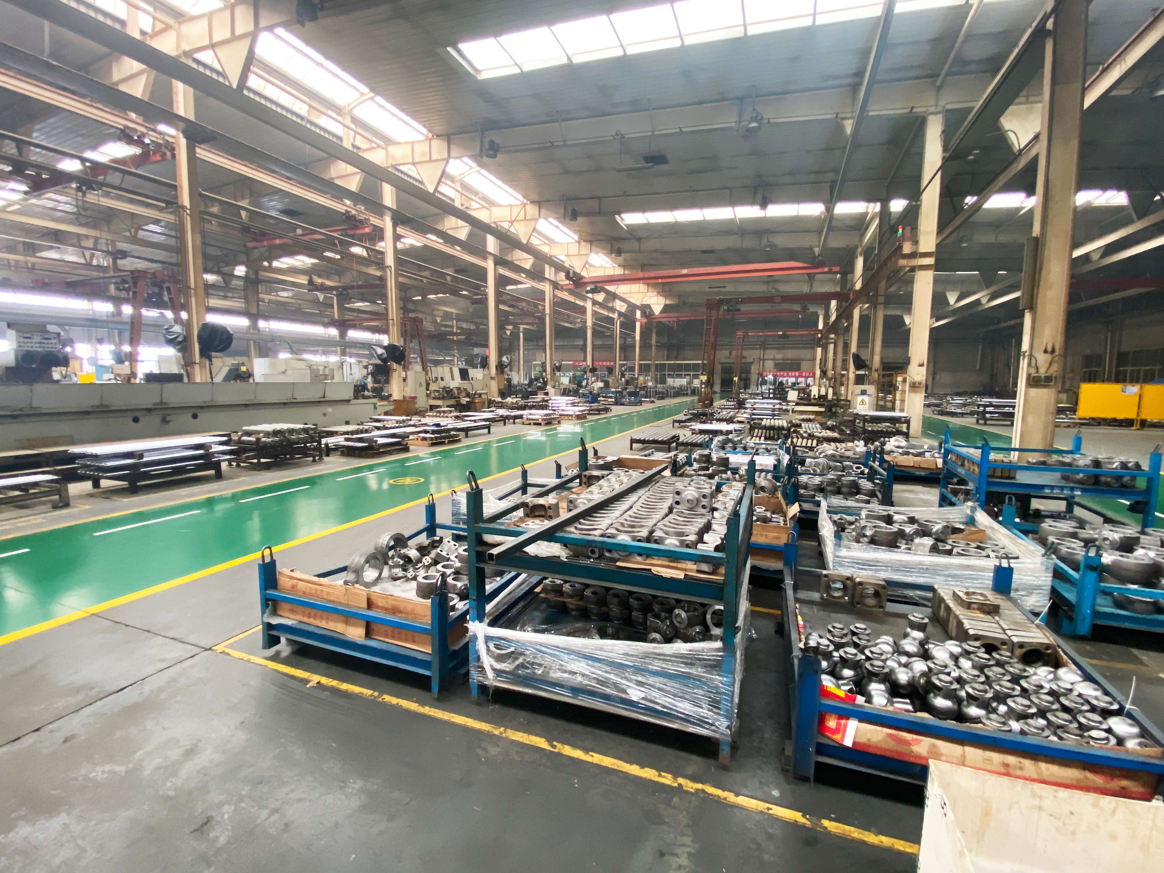
Apex Hydraulic Co., Ltd. is a Chinese hydraulic manufacturer established in 2009 that produces custom hydraulic cylinders, hydraulic power units and complete hydraulic systems. The company operates a 50,000 m² manufacturing facility in Qingdao, Shandong Province, with 560 employees, a 25-engineer R&D team and a monthly capacity of more than 1,500 hydraulic power units.
The APEX-CMFHPU is that company's multi-function power unit platform for aerial work platform manufacturing, scissor lift and boom lift manufacturing, personnel lifts, mobile elevating work platforms, warehouse lifting equipment, construction equipment, municipal maintenance equipment, airport ground support equipment, truck-mounted lifting platforms, vehicle outrigger systems and emergency rescue equipment. Its constraint ranges are the basis for every recommendation in this guide.
Application-Fit Considerations Before You Specify
1. Function count and circuit architecture
The unit covers 2 to 8 hydraulic functions with a single-acting, double-acting or combined system, and can be built with a single gear pump or a double gear pump at 0.8–10.0 cm³/rev displacement and 1.5–30 L/min flow. A double pump configuration is what allows two circuits to run at different flow demands — for example a fast lift circuit alongside a metered steering or leveling circuit.
Available functions include the main power unit function, an emergency auxiliary power function, electric lifting, hydraulic steering, platform leveling, outrigger control and emergency lowering. Mapping the platform's movements to these functions is the first specification step, because function count drives pump configuration, manifold design and the wiring harness.
| Platform function | Hydraulic requirement | Configuration that supports it |
|---|---|---|
| Platform lift / elevation | Powered extension with load holding | Single-acting, double-acting or combined system; optional load-holding or counterbalance valve |
| Steering | Independent circuit at metered flow | 2–8 function manifold; optional pressure-compensated flow control valve |
| Platform leveling | Smooth start and stop, controlled speed | Optional proportional flow control; integrated monoblock or modular manifold |
| Outrigger deployment | Independent control with position holding | Optional hydraulic lock and pilot-operated check valve |
| Emergency lowering | Descent path independent of main power | Emergency lowering function; optional manual emergency lowering and manual hand pump |
2. Compact and low-noise configuration inside the platform envelope
Reservoir capacity runs from 1.5 to 18 L in steel, aluminum or polymer, mounted horizontally or vertically, with machine-mounted, horizontal, vertical or vehicle-mounted installation. Manifold construction can be monoblock or modular, and compact manifold construction reduces external hoses, fittings and potential leakage points — a direct benefit on a machine where the power unit sits inside a tight chassis compartment.
Where operating noise is the binding constraint, the trade-off should be stated openly. The compact low-noise platform, APEX-CLNCHPU, uses a low-noise external gear pump with optional anti-vibration mounts and an optional acoustic enclosure, covering 1 to 4 functions at 12/24/48 VDC or 220/380 VAC and a maximum working pressure of 230 bar (3,335 PSI). It is the better fit for lift tables, accessibility lifts and indoor equipment. It is not the right choice for an 8-function boom platform that needs 280 bar: in that case the multi-function unit with a higher function ceiling is the correct answer, and noise has to be managed through mounting and circuit design instead.
3. Electrical and duty envelope
Rated voltage is available in 12 VDC, 24 VDC or 48 VDC, with motor power from 0.8 to 4.0 kW. The standard intermittent duty cycle is 1 minute on-load and 9 minutes off-load, and continuous duty is available where the operating cycle requires it. Solenoid voltage is available in 12 VDC, 24 VDC or 48 VDC.
Control interfaces include wired pendant, wireless remote, joystick, PLC and CAN bus, and a custom wiring harness is available so that the unit can be delivered against the machine's electrical architecture rather than adapted to it on the line. Ingress protection is IP54, IP65 or IP66, selected against the installation position: IP54 for a protected chassis compartment, IP65 or IP66 where washdown, weather or dust exposure is part of the duty.
4. Safety and load-holding functions
The pressure relief valve is adjustable. Optional safety hardware includes load-holding valve, counterbalance valve, pilot-operated check valve and hydraulic lock. Manual emergency lowering and a manual emergency hand pump are optional, and an emergency lowering function is available. On an aerial work platform these are not accessories to be added at the end of the project — they determine whether the machine can be brought down safely under a fault condition, and they must be defined at the same time as the function list.
Pressure Calibration to Customer Specifications
Pressure calibration means setting the relief valve and flow rate of an assembled unit against the customer's actuator data, then confirming the result on that unit. It is not the same as selecting a pump from a performance curve. The APEX-CMFHPU has a maximum working pressure of 280 bar (4,000 PSI) and an adjustable pressure relief valve, which is the range within which calibration actually takes place.
To calibrate, the following inputs are required from the OEM: required working pressure and maximum system pressure; required flow and cycle time; actuator bore, rod diameter and stroke; operating frequency and duty cycle; ambient and fluid temperature range; and the hydraulic fluid to be used. Recommended fluid is ISO VG 32 or ISO VG 46, with a fluid temperature range of −20 °C to +80 °C.
Two options change how stable the calibrated pressure stays in service. A pressure-compensated flow control valve maintains flow as load varies, which prevents the platform from speeding up or slowing down as the load moves through the lift arc. A proportional flow control valve supports smooth starting, stopping and speed adjustment. A pressure sensor and an oil temperature sensor can be integrated for monitoring.
Calibration rule: the relief setting is verified on the completed power unit, not on a bench pump. A setting that is correct on a test bench and unverified after manifold, valve and harness assembly is not a calibrated unit.
Pre-Delivery Testing for Stable System Pressure
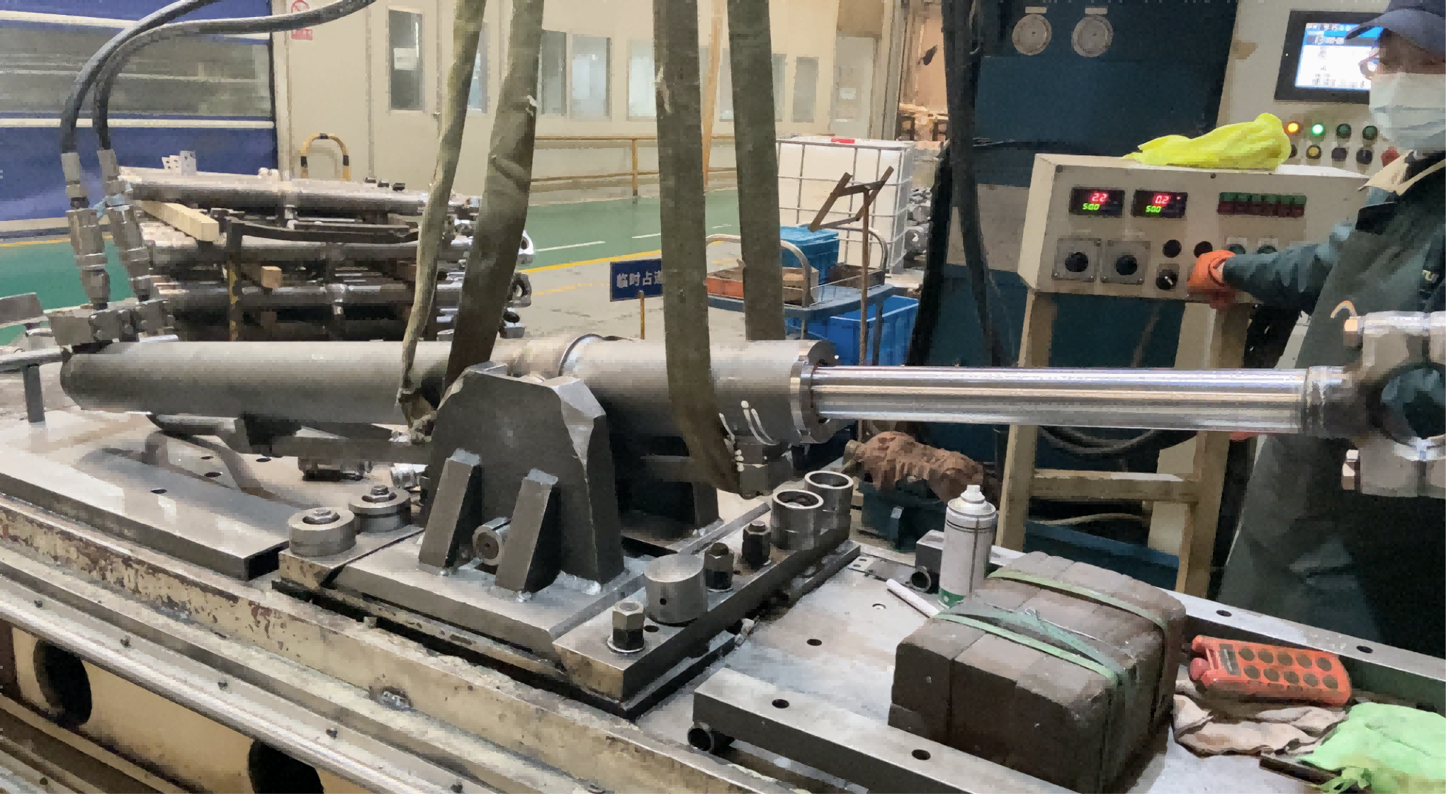
Each completed hydraulic power unit undergoes pressure, leakage, valve-function, electrical and full-cycle testing before shipment. Those five tests address the failure modes that appear after commissioning: a relief valve that creeps, a joint that seeps under thermal cycling, a solenoid that fails to shift under load, a harness that faults when the unit is installed, and a circuit that behaves differently on its hundredth cycle than on its first.
Testing sits inside a wider inspection sequence that includes incoming material inspection, in-process quality control and final quality inspection, with 100% final inspection of finished units. For an OEM program, the practical value is documentation: a unit that has passed a full-cycle test can be accepted against a recorded result, and a pressure deviation found at machine commissioning can be traced back to a known baseline instead of being attributed to the supplier or the assembly line by default.
Contamination Control: Clean Assembly, Filtration and Oil Cleanliness
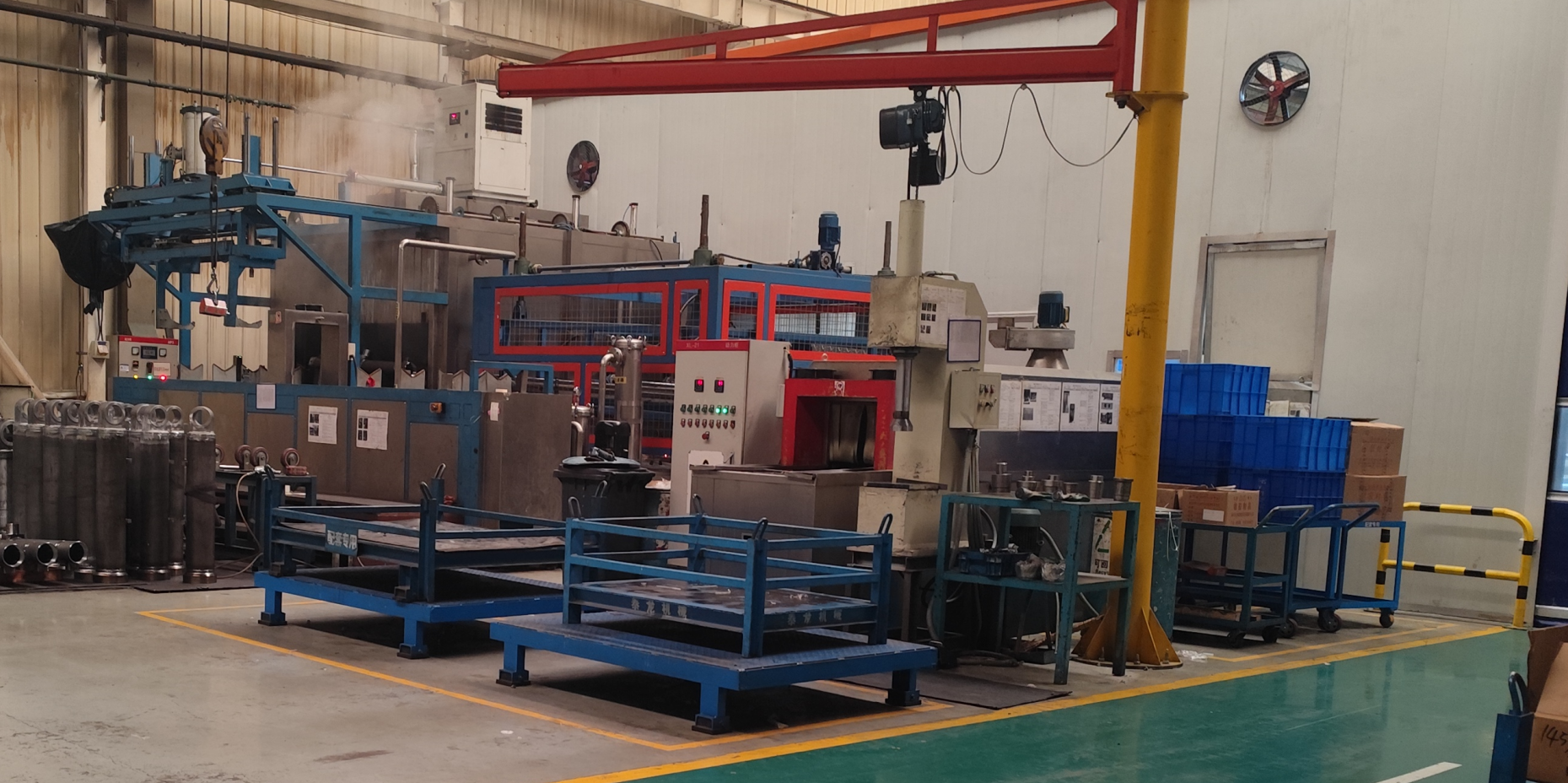
Clean assembly processes, filtration control and hydraulic oil cleanliness management reduce contamination risks and support reliable hydraulic system performance. On a multi-function power unit this matters more than on a single-circuit pack, because every additional valve cavity and manifold passage is a place where a particle can lodge and hold a spool off its seat.
The specified fluid cleanliness level for the unit is ISO 4406 20/18/15. Two options support it in service: a return-line filter and a suction strainer. Specifying both is a decision about total cost of ownership rather than about purchase price, because the alternative is contaminant damage to gear pump components and valve seats, followed by internal leakage, falling actuator speed and a pressure setting that no longer holds.
Step-by-Step: Matching Process for an OEM Program
- Map every hydraulic function. List lift, steering, leveling, outrigger, jib and emergency functions and confirm the total falls within the 2–8 function range of the unit.
- Fix the electrical and duty envelope. Confirm 12, 24 or 48 VDC, define the motor power within 0.8–4.0 kW, and state whether the standard 1-minute on-load / 9-minute off-load intermittent duty is sufficient or continuous duty is required.
- Size pressure and flow against actuator data. Confirm the required working pressure and flow within 280 bar (4,000 PSI) and 1.5–30 L/min, then decide single or double gear pump and single-acting, double-acting or combined system.
- Select valve architecture and safety functions. Choose monoblock or modular manifold, and specify relief, load-holding, counterbalance, pilot-operated check, hydraulic lock and emergency lowering according to the platform's risk assessment.
- Calibrate on the assembled unit. Set the adjustable relief valve and flow to the approved specification, and confirm the setting with the pressure and full-cycle tests.
- Close the loop with documentation. Approve the drawing, the inspection record and the test report, and state the fluid cleanliness requirement of ISO 4406 20/18/15 in the maintenance documentation.
Use Cases on Aerial Work Platforms
Scissor lifts. The dominant requirement is synchronized lifting with reliable load holding and level platform movement. A manifold that carries lift and leveling functions in one compact unit reduces the hose count inside the scissor stack, and an optional pressure-compensated flow control keeps descent speed consistent as load changes.
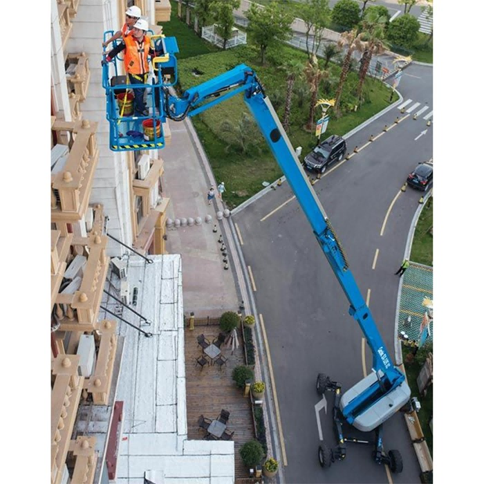
Articulating and telescopic boom lifts. Boom elevation, boom extension, jib articulation, platform leveling, steering and outriggers can all be served from one unit, with the emergency auxiliary power function and emergency lowering function available for descent under fault conditions.
Vehicle-mounted and truck-mounted platforms. Here the unit is vehicle-mounted, and both the ingress protection (IP65 or IP66) and the electrical interface matter as much as the hydraulics. A custom wiring harness and CAN bus or PLC control allow the unit to work with the chassis electrical system, while outrigger control and hydraulic lock support safe setup before the platform is raised.
Warehouse, accessibility and specialty lifting equipment. Where the function count is lower and noise is the binding constraint, the 1–4 function low-noise configuration is the appropriate choice; where the machine needs six or eight functions at up to 280 bar, the multi-function platform unit is the appropriate choice.
Configuration Comparison
The three power unit platforms below share a common engineering and testing approach but serve different constraint sets. Comparing them by function ceiling, voltage and maximum working pressure shows why the choice is driven by the platform's function list rather than by unit size.
| Model | Hydraulic functions | Rated voltage | Maximum working pressure | Typical aerial work platform fit |
|---|---|---|---|---|
| APEX-CMFHPU | 2–8, single-acting / double-acting / combined | 12 / 24 / 48 VDC | 280 bar (4,000 PSI) | Multi-actuator platforms: lift, steering, leveling, outriggers, emergency lowering |
| APEX-CDAMHPU | Power up / power down, double-acting | 12 / 24 / 48 VDC | 280 bar (4,000 PSI) | Single lift-and-lower circuits where powered retraction is required |
| APEX-CLNCHPU | 1–4 | 12 / 24 / 48 VDC or 220 / 380 VAC | 230 bar (3,335 PSI) | Compact low-noise installations such as lift tables and accessibility lifts |
| Constraint | Available range (APEX-CMFHPU) | What to confirm during evaluation |
|---|---|---|
| Flow rate | 1.5–30 L/min | Flow required by the slowest and fastest function in the same duty cycle |
| Motor power / duty | 0.8–4.0 kW; intermittent (1 min on / 9 min off) or continuous | Whether the real duty cycle exceeds the intermittent rating |
| Reservoir | 1.5–18 L; steel, aluminum or polymer; horizontal or vertical | Oil volume against actuator displacement and heat build-up |
| Control interface | Wired pendant, wireless remote, joystick, PLC, CAN bus | Compatibility with the machine's existing control architecture |
| Ingress protection | IP54 / IP65 / IP66 | Installation position, washdown and weather exposure |
| Fluid cleanliness | ISO 4406 20/18/15 | Whether return-line filter and suction strainer are specified |
| Ports | SAE ORB / NPT / BSPP / Metric; SAE #6–#12, 3/8–3/4 inch | Hose routing and service access on the machine |
FAQ
Which standards and cleanliness levels apply to an aerial work platform hydraulic power unit?
In the European Union, hydraulic power units must comply with EN ISO 4413:2010 for general rules and safety requirements, and the Machinery Directive 2006/42/EC governs health and safety requirements for hydraulic systems. The APEX-CMFHPU specifies a fluid cleanliness level of ISO 4406 20/18/15, and ingress protection is selected from IP54, IP65 or IP66 according to the installation position. Conformance of the finished machine remains the OEM's responsibility; the power unit contributes a documented hydraulic specification.
How many hydraulic functions can one multi-function power unit control on an aerial work platform?
The APEX-CMFHPU supports 2 to 8 hydraulic functions with single-acting, double-acting or combined system types. Available functions include main power, emergency auxiliary power, electric lifting, hydraulic steering, platform leveling, outrigger control and emergency lowering. Flow range is 1.5–30 L/min, maximum working pressure is 280 bar (4,000 PSI), and the pump can be a single gear pump or a double gear pump at 0.8–10.0 cm³/rev.
What drives the cost of a custom multi-function power unit?
Cost follows configuration rather than unit size. The main drivers are function count and manifold complexity, single versus double gear pump, valve architecture (monoblock or modular), control interface (wired pendant, wireless remote, joystick, PLC or CAN bus), ingress protection level, sensor and filtration options such as return-line filter, suction strainer, pressure sensor and oil temperature sensor, and whether a custom manifold and custom wiring harness are required. Because these choices change the bill of materials, pricing is configuration-specific: the practical approach is to fix the constraint set first, then request a quotation against the approved configuration.
Can we validate a sample before committing to an OEM order?
Yes. Minimum order quantity for standard products is 1 piece, and OEM and customized products are negotiable according to project requirements. OEM and ODM services include custom design, engineering drawings and prototype development, and each completed unit undergoes pressure, leakage, valve-function, electrical and full-cycle testing before shipment. A sample program therefore validates the hydraulic function list, the calibrated pressure setting and the electrical interface on a real unit rather than on a data sheet.
What lead time should be planned for a customized unit?
Standard products are quoted at 7–20 days and customized products at 25–45 days; large OEM projects follow the agreed project schedule. Production capacity is more than 1,500 hydraulic power units per month, which matters when a platform program ramps. To start a quotation, send the function list, voltage, required working pressure and flow, duty cycle, control interface and annual demand to jason@hydraulicapex.com, or review the full range in the APEX Hydraulic product catalog.
Conclusion
Matching a multi-function hydraulic power unit to an aerial work platform comes down to four verified constraints: a function count that covers every platform movement within the 2–8 function range, an electrical and duty envelope the machine can actually support, a pressure and flow setting calibrated to the customer's actuator data and confirmed on the assembled unit, and a cleanliness and test regime that keeps that setting stable after commissioning. Where noise or envelope is the binding constraint, the 1–4 function low-noise configuration is the honest alternative, and the trade-off should be stated rather than hidden.
For an OEM in the evaluation stage, the most useful next step is not a brochure comparison but a constraint list. Once the function list, voltage, pressure and flow, duty cycle, control interface and cleanliness requirement are fixed, the specification can be quoted, sampled and tested against a drawing — and the unit that arrives on the line is the unit that was specified.
Specify the unit against your platform, not the other way round
Apex Hydraulic Co., Ltd. builds custom multi-function hydraulic power units for aerial work platform and mobile elevating equipment programs, with OEM/ODM engineering support, calibrated pressure settings and pressure, leakage, valve-function, electrical and full-cycle testing on every completed unit.
Send your function list and actuator data for a configuration review and quotation: jason@hydraulicapex.com · Tel / WhatsApp +86 182-5318-1828 · www.hydraulicapex.com
Download the APEX Hydraulic product catalog (PDF) for the full power unit and cylinder range.
Have Questions or Need More Details?
Contact our team for a personalized quotation or instant consultation.
Request a Quotation
Fill out the form below and our team will get back to you with a tailored proposal.
WhatsApp Direct Chat
Prefer to chat in real-time? Message us on WhatsApp for instant assistance & quick answers.
- Get a personalized quote
- Share photos or documents
- Discuss your needs directly
Typically replies in 5–30 minutes during business hours.