On-Load vs Off-Circuit Tap Changer: A Custom Transformer Comparison Guide
The practical difference between the two tap-changing methods is whether the tap can be moved while the transformer stays energised. An on-load tap changer changes the turns ratio while the unit remains in service, so the output voltage can be regulated continuously as grid load and upstream voltage vary. An off-circuit tap changer can only be repositioned after the transformer has been de-energised, so it corrects a seasonal or planned voltage change and nothing faster. That one distinction determines the regulating range you can specify, the outages you must plan, and how much component, testing and maintenance content the order carries.
This guide compares the two methods the way they are actually decided on projects: transmission and large power transformers that have to hold voltage within limits, distribution transformers that only need occasional correction, and mixed fleets where both appear on the same site. Apex Power Systems (Nanjing) Co., Ltd. is an international trading and supply-partner company based in Nanjing, China, specialising in power transformers, box-type substations and complete substation solutions for overseas utility, EPC and industrial buyers; the engineering and test evidence quoted below comes from the audited manufacturing partners it manages on the buyer's behalf.

Custom transformer manufacturing environment — tap-changing configuration is fixed at design stage and verified at factory testing.
Problem Definition: Why a Fixed Turns Ratio Is Rarely Enough
A transformer's turns ratio is manufactured, not adjusted at will. The only way to correct the output voltage in service is to change the number of turns in circuit — that is what a tap changer does. Three things move the voltage away from its nominal value in normal operation:
- Upstream voltage variation. The supply voltage presented to a substation or plant rises and falls with system load, generation mix and the tap position of transformers further up the network.
- Load-dependent voltage drop. Load current flowing through the transformer impedance produces a voltage drop that grows with load, which is why a lightly loaded unit and a fully loaded unit do not deliver the same secondary voltage.
- Renewable and storage-driven variability. Solar, wind and energy-storage plants present voltage conditions that change with generation output rather than with a predictable daily curve.
The specification problem is that a regulating requirement is easy to leave implicit. A buyer who does not state how often the voltage must be corrected, and within what range, usually receives a unit with a modest off-circuit tap range on a fixed platform. The gap only appears at commissioning, when the secondary voltage cannot be brought inside limits without an outage and a de-energised tap change.
Industry Background: Regulation Requirements Are Widening
The commercial context supports putting this decision earlier in the project. Grand View Research projects the global distribution transformer market to grow from USD 26.0 billion in 2026 to USD 47.7 billion by 2033, a compound annual growth rate of 9.1%. Trade data points the same way: the OEC reports that global exports of electrical transformers rated above 500 kVA (HS 850434) reached USD 2.5 billion in 2024, 12.7% higher than the previous year.
Two other shifts are shaping specifications. First, efficiency regulation is tightening: China's GB 20052-2024 on minimum allowable energy-efficiency values and energy-efficiency grades for power transformers took effect on 1 February 2025, and the U.S. Department of Energy rule published in 2024 under 10 CFR Part 431 moves distribution transformers toward amorphous electrical steel from 2029. Second, the load profile itself has changed — step-up substations for PV, wind and storage plants, and large data-centre and AI computing park supplies, are being specified where supply voltage varies enough that continuous regulation is worth designing in rather than correcting afterwards.
Detailed Solution: How the Two Methods Actually Work
On-load tap changer (OLTC): regulation without an outage
In an on-load tap changer the transformer carries a regulating, or tapping, winding that is divided into steps. A diverter switch selects the step through transition resistors or vacuum interrupters, so that the load current always has a continuous path and no step is broken under load. That continuity of current is precisely what makes regulation possible while the unit remains energised, and it is the mechanism that distinguishes an OLTC from every simpler arrangement.
The consequences for a project follow directly from that mechanism. The tap changer is a separate electromechanical assembly with a drive and a control, not merely a link in the winding; its rating, step voltage and operating sequence are fixed by the design and are verified during factory testing; and it becomes a maintenance item in service, which is why the tap-changer operation counter is one of the readings recorded during routine transformer maintenance.
A concrete example from the supply range managed by Apex shows how much regulating range this makes available. The SFZ-250000/345 three-phase oil-immersed on-load voltage regulating power transformer is rated 250/250 MVA at 345/34.5 kV, Dyn1, with cooling stages ONAN at 185 MVA, ONAF1 at 225 MVA and ODAF2 at 250 MVA. Its tap range is (345 +17/−17 × 0.625%)/34.5 kV — thirty-four steps of 0.625%, symmetrical about nominal — and it uses a type 3×SHZVI-400/363C-18353W on-load tap changer from the German MR or ABB brands. Insulation levels for the same unit are a lightning impulse withstand of 1175 kV on the HV side and 200 kV on the LV side, with a switching impulse withstand of 975 kV.
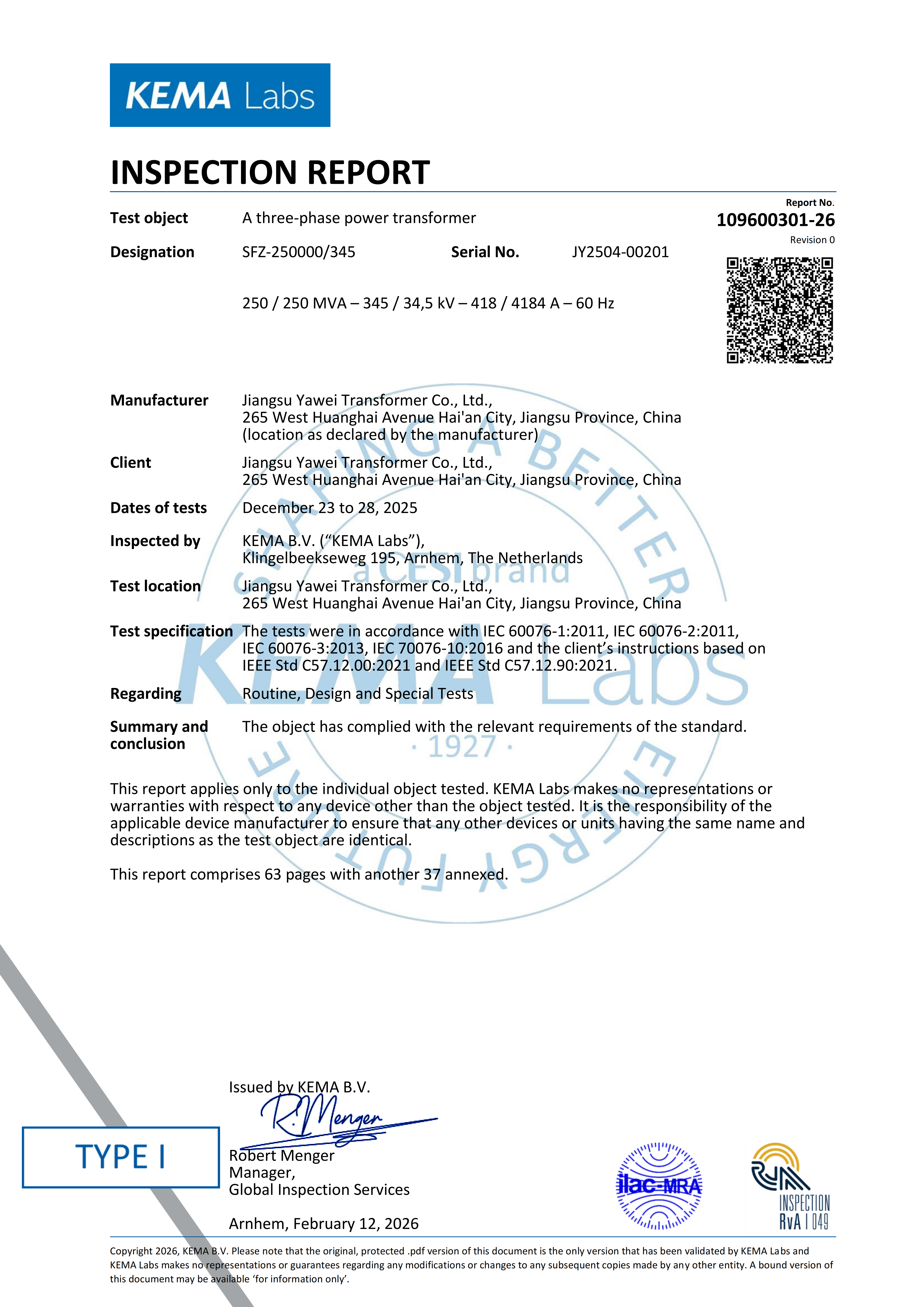
Independent verification of the OLTC-equipped 250 MVA / 345 kV power transformer: KEMA Labs (KEMA B.V., Arnhem, the Netherlands) type test report, tested to IEC 60076-1/-2/-3/-10 and IEEE C57.12.00 / C57.12.90.
Independent test evidence exists for the tap-changing design rather than only a data sheet. KEMA Labs issued a report for the 250 MVA / 345 kV three-phase power transformer covering routine, type and special tests to IEC 60076-1:2011, IEC 60076-2:2011, IEC 60076-3:2013 and IEC 60076-10:2016; a later KEMA report covers tests witnessed December 2025 to the same IEC parts plus IEEE C57.12.00:2021 and IEEE C57.12.90:2021, issued on 12 February 2026. A TÜV Rheinland type test report (CN231PY4 001) for a three-phase outdoor oil-immersed power transformer adds a further independent verification route.
Off-circuit tap changer: planned, offline correction
An off-circuit tap changer is operated with the transformer de-energised. It changes the effective turns ratio by reconnecting tap links or an offline switch, and its purpose is to place the unit on the right ratio for the network it is installed in, or to correct for a seasonal drift in supply voltage — not to follow load second by second.
That limitation is also its commercial advantage, because the regulating mechanism is a fraction of the complexity. The same product platforms make the contrast clear. The S13 / S14 / S15 oil-immersed distribution transformer covers 30–3,150 kVA in the 10 kV class and 3,150–31,500 kVA in the 35 kV class, with HV from 6 kV to 35 kV, LV from 0.4 kV to 10.5 kV, Dyn11 or Yyn0 vector groups and ONAN cooling, and it is offered with either off-circuit tap changing (±2×2.5%) or on-load tap changing. The SC10 / SZ18 / SZ20 new energy transformer for PV, wind and energy-storage duty, 500–12,500 kVA at 10 kV and 1,000–12,500 kVA at 35 kV, is specified with off-circuit tap changing of ±2×2.5% or ±5%.
It is a mistake to assume that off-circuit tap changing is only for small distribution units. A 75,000 kVA, 230 kV power transformer supplied for a national grid substation in Ecuador — a three-phase, two-winding oil-immersed unit with YNd11 connection — was custom-engineered to a 230±2×2.5%/13.8 kV specification with off-circuit tap changing. Where the supply voltage is stable and correction is infrequent, that is the correct and more economical choice even at high voltage.
Trade-offs in complexity, maintenance and cost
The trade-off is not simply "better" versus "cheaper". The on-load solution buys regulation without outages and pays for it with component content, engineering content, test scope and in-service maintenance. The off-circuit solution buys simplicity and lower component content and pays for it with an outage every time a correction is needed. The decision variable that settles the comparison is how often the voltage actually has to be corrected on that particular network — a figure the buyer knows and the supplier does not.
Step-by-Step Breakdown: How to Specify the Right Method
- Quantify the voltage variation first. Record the highest and lowest sustained supply voltage and the voltage drop at full load. The regulating range should follow from these measured figures, not from the range that happened to be used on the last project.
- Decide whether correction can wait for an outage. If the voltage must be held continuously as load and upstream conditions change, specify an on-load tap changer. If a correction once or twice a year is sufficient, an off-circuit tap changer is the appropriate and less complex choice.
- State the tap range and step size explicitly on the data sheet. Write the range in the unambiguous form used on drawings — for example ±2×2.5%, or (345 +17/−17 × 0.625%)/34.5 kV — and state the step, so that no interpretation is possible between enquiry, drawing and rating plate.
- Fix the vector group in the same breath. Dyn1, Dyn11, Yyn0 and YNyn0d11 configurations determine whether the unit can be paralleled with existing transformers, so the tap data and the vector group belong in the same specification paragraph.
- Check the interaction with the cooling class. Permissible loading and regulation are linked through the cooling stage — ONAN, ONAF1 and ODAF2 correspond to different ratings on the same 250 MVA / 345 kV unit — so the cooling class must be consistent with the loading assumed when the tap range was chosen.
- Name the tap changer type and brand at tender stage. Specifying the tap changer assembly, not just the tap range, prevents substitution: the 250 MVA / 345 kV unit carries a type 3×SHZVI-400/363C-18353W unit from the German MR or ABB brands, and that is what a buyer should see on the approved drawing.
- Define the test and witness regime. Routine, type and special tests per IEC 60076 (and IEEE C57.12 where North American practice applies) should be stated, together with witness testing and third-party inspection where the project requires it. The tap-changer rating and operating sequence are verified during factory testing, not assumed.
- Plan the in-service checks. For an OLTC-equipped unit, maintenance includes operating the tap changer and recording the operation counter alongside oil testing (dielectric strength, moisture and dissolved gas analysis), breather inspection and cooling-system checks. Trending those readings detects developing faults earlier than any single measurement.
- Confirm documentation and site support. Drawings, factory test reports, operating manuals, installation guidance and commissioning support should be listed in the scope at the same time as the hardware, so that the regulating function is proven on site and not only in the factory.
Use Cases: Where Each Duty Type Applies
Tap-changing decisions rarely appear in isolation; they appear attached to a duty. The delivered projects below illustrate the two duty types. Where the source record states the tap-changing configuration, it is given; where it does not, the tap-changing method remains a project-specific specification decision.
Continuous-regulation duty — substation, transmission and large industrial supplies.
- Four 110 kV power transformers for a utility substation in Azerbaijan, covering design, manufacturing, testing and installation guidance; commissioned, handed over and operating in the substation for five years.
- 115 kV substation transformer equipment for a transmission company in Tajikistan, covering design, supply and installation guidance, energised and operating on a two-year implementation period.
- A 132 kV power transformer for a steel-plant substation in Seville, Spain, meeting industrial load requirements and in operation since delivery.
- A 345 kV fully insulated power transformer for a US–Georgia transmission company, four units, covering design, engineering, manufacturing, testing, delivery, installation guidance and commissioning — a UHV reference in the 345 kV class.
- 115 kV substation equipment for Puerto Rico, including a 40 MVA large transformer for an island power system, operating since 2023.
- A 40,000 kVA energy-storage project in Bulgaria, with the transformer integrated with the storage system and commissioned for grid-scale connection.
Planned-correction duty — distribution and commercial supplies.
- A 15 MVA pad-mounted transformer programme in the United States, 15 units delivered and installed for the North American distribution network to ANSI/IEEE standards.
- Distribution transformers from 63 kVA to 2,500 kVA supplied across multiple substations in Uzbekistan, part of a programme that also included 40 MVA, 16 MVA and 10 MVA power transformers.
- Two S13-1250/10/0.4 oil-immersed distribution transformers for the Myanmar Conch cement plant, in operation since 2023.
- An SCB10-1000 kVA dry-type transformer at 13.2/0.4 kV combined with an SG-400 kVA isolation transformer at 0.38/0.22 kV for Consorcio Industrial S.A., an industrial distribution package in operation since 2023.
- A 75,000 kVA, 230 kV power transformer with off-circuit ±2×2.5% tap changing for a national grid substation in Ecuador — high-voltage duty where regulation is infrequent and the simpler method was specified.
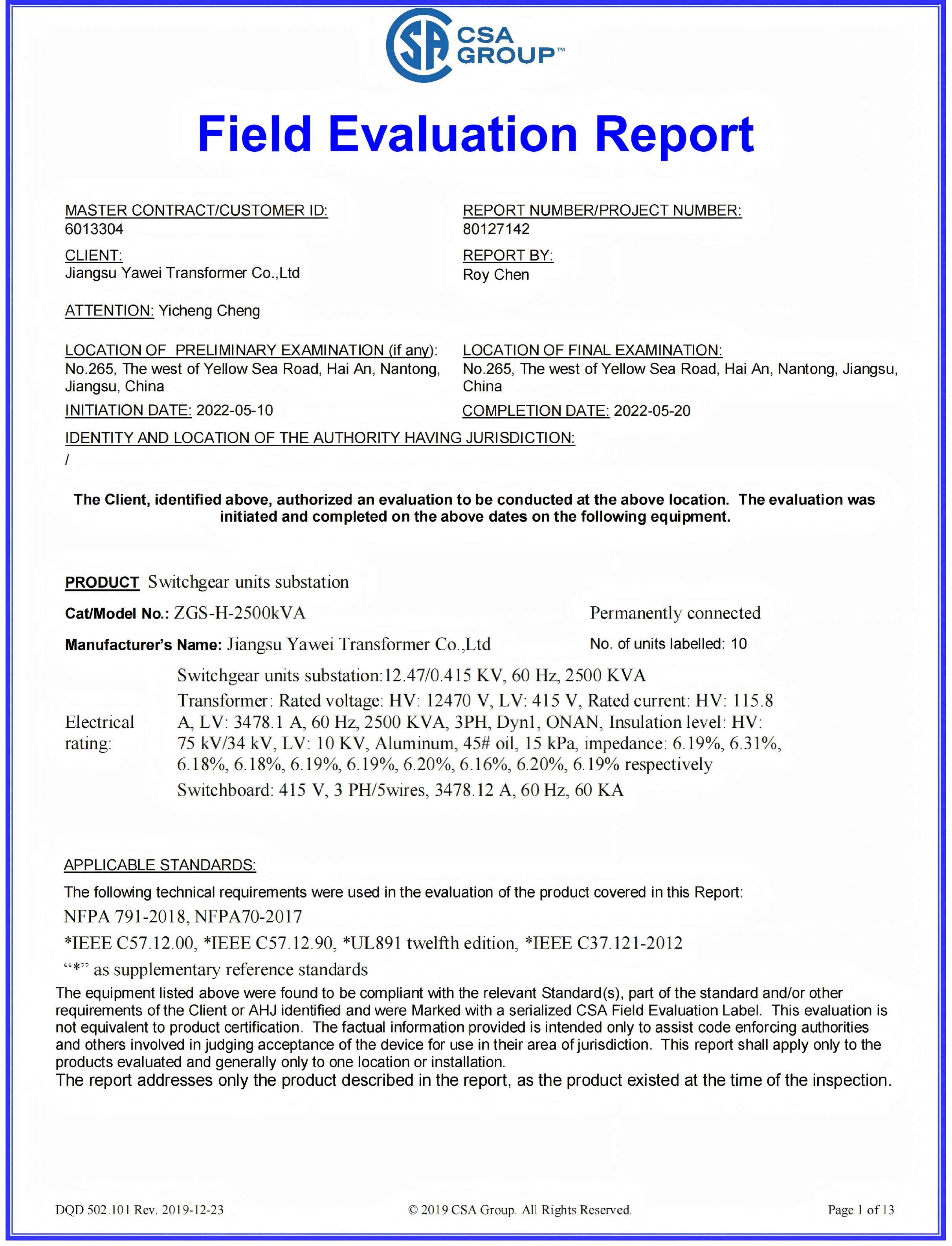
Market-access documentation on the same supply chain: CSA Group field evaluation report covering substation equipment, assessed against NFPA 791-2018, UL 891 and IEEE C57.12.00 / C57.12.90 — relevant when a tap-changing transformer is packaged with switchgear into a substation.
Comparison Table: On-Load vs Off-Circuit Tap Changing
| Comparison dimension | On-load tap changer (OLTC) | Off-circuit tap changer |
|---|---|---|
| Can the tap be changed while energised? | Yes — regulation takes place with the transformer in service | No — the transformer must be de-energised before the tap is moved |
| Operating mechanism | A diverter switch selects steps of a regulating winding through transition resistors or vacuum interrupters, so load current always has a continuous path and no step is broken under load | Tap links or an offline switch are reconnected with the unit out of service |
| Nature of regulation | Continuous — follows load and upstream voltage variation | Discrete and planned — a seasonal or one-off correction |
| Tap range examples in this supply range | (345 +17/−17 × 0.625%)/34.5 kV on the 250 MVA / 345 kV power transformer; ±10% or customised on large power transformers from 10 kV to 765 kV | ±2×2.5% on the S13 / S14 / S15 oil-immersed distribution transformer; ±2×2.5% or ±5% on the SC10 / SZ18 / SZ20 new energy transformer; 230±2×2.5%/13.8 kV on the Ecuador 75 MVA unit |
| Typical duty | Transmission and large power transformer duty, large industrial incoming supplies, and renewable step-up or data-centre supplies where voltage varies | Distribution duty, commercial and industrial auxiliary supplies, and installations where the network voltage is stable |
| Availability in range | Large power transformers 10–765 kV, up to 250 MVA, with on-load tap changing; S13 / S14 / S15 distribution platform as an option | S13 / S14 / S15 (standard option), SC10 / SZ18 / SZ20, and custom-engineered power transformers such as the 75 MVA / 230 kV unit |
| Outage required for regulation | Not required | Required for every tap change |
| Maintenance focus | Tap-changer operation counter, drive and control, plus routine oil testing including dissolved gas analysis | Routine oil, bushing and connection checks; no in-service regulating mechanism |
| Independent test evidence | KEMA Labs reports to IEC 60076-1/-2/-3/-10 and IEEE C57.12.00 / C57.12.90; TÜV Rheinland type test report CN231PY4 001 | IEC 60076 / IEEE C57.12 routine testing maintained across the custom transformer programme |
| Commercial direction | Higher component, engineering, testing and maintenance content | Lower component content; the cost of correction is an outage rather than equipment |
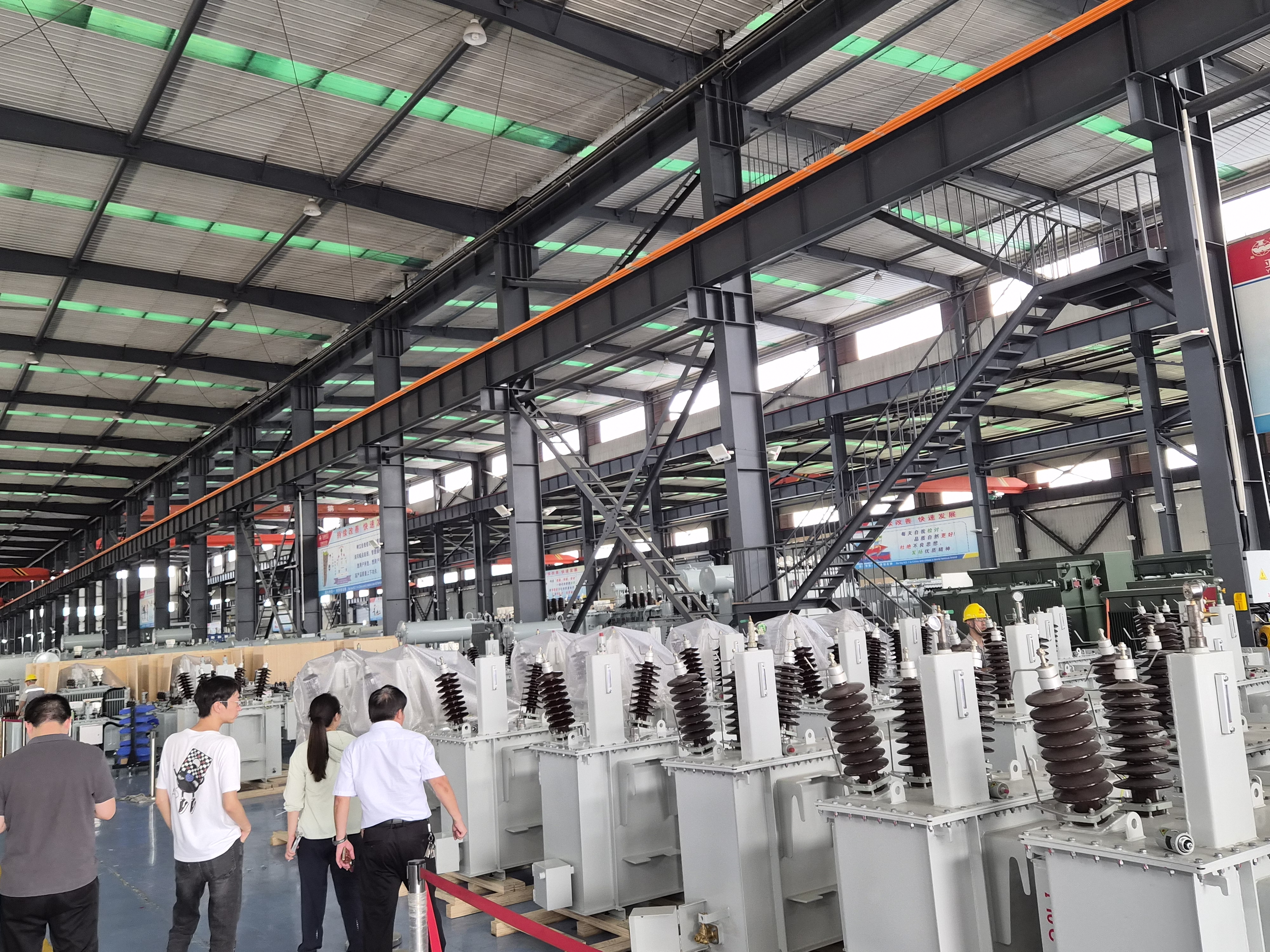
Production capability behind the tap-changing options: custom voltage ratios, capacities, impedances, vector groups and tap ranges are part of the standard engineering scope.
Frequently Asked Questions
Which standards and tests verify the tap-changing function of a custom transformer?
Tap-changing equipment and the transformer it sits on are verified together at the factory. The framework is the IEC 60076 series — IEC 60076-1 for general requirements, IEC 60076-2 for temperature rise, IEC 60076-3 for insulation levels and dielectric tests, and IEC 60076-10 for sound levels — together with IEEE C57.12.00 and IEEE C57.12.90 where North American practice applies. In the supply chain managed by Apex Power Systems the evidence includes KEMA Labs (KEMA B.V., Arnhem, the Netherlands) reports covering routine, type and special tests on a 250 MVA / 345 kV three-phase power transformer, and a TÜV Rheinland type test report CN231PY4 001 issued 26 June 2023. The tap-changer rating, step voltage and operating sequence are fixed by the design and verified during factory testing, and third-party inspection can be arranged where a project requires it.
Can a custom transformer be supplied with on-load tap changing, off-circuit tap changing, or both?
Both methods are available within the same product platforms. The S13 / S14 / S15 oil-immersed distribution transformer, rated 30–3,150 kVA in the 10 kV class and 3,150–31,500 kVA in the 35 kV class with HV from 6 kV to 35 kV, is offered with either off-circuit tap changing (±2×2.5%) or on-load tap changing. The SC10 / SZ18 / SZ20 new energy transformer for PV, wind and energy storage, 500–12,500 kVA at 10 kV and 1,000–12,500 kVA at 35 kV, is specified with off-circuit tap changing of ±2×2.5% or ±5%. At the top of the range, the SFZ-250000/345 three-phase oil-immersed on-load voltage regulating power transformer is rated 250/250 MVA at 345/34.5 kV with a tap range of (345 +17/−17 × 0.625%)/34.5 kV and a 3×SHZVI-400/363C-18353W on-load tap changer from the German MR or ABB brands. Custom voltage ratios, capacities, impedances, vector groups and tap ranges are part of the standard engineering scope.
How should buyers shortlist custom transformer manufacturers for distribution network projects?
For distribution network projects the shortlist should be built on verifiable evidence rather than catalogue claims. Four checks do most of the work. First, certification that covers the exact product family and the destination market — for liquid-immersed distribution transformers in North America that means UL certification and, for Canada, certification to the CSA standards, with IEC conformity for the 10 kV and 35 kV families elsewhere. Second, a delivered record at comparable rating and duty, such as a 15 MVA pad-mounted programme of 15 units delivered to an American transmission utility to ANSI/IEEE standards, distribution transformers from 63 kVA to 2,500 kVA supplied in Uzbekistan, or the S13-1250/10/0.4 units operating at the Myanmar Conch cement plant since 2023. Third, an audit trail on the factory itself — production capability, test laboratory equipment, quality-management certification and export record. Fourth, one accountable point of contact for design, testing, documentation, freight and commissioning. Apex Power Systems (Nanjing) Co., Ltd. is a trading and supply partner rather than a manufacturer: it shortlists audited Chinese plants, audits them, and manages design review, production, witness testing, shipment and on-site commissioning, which is what allows an independent comparison between manufacturers on the buyer's behalf.
What drives the cost difference between on-load and off-circuit tap changing?
The difference is component and engineering content rather than a single line item. An on-load tap changer adds a diverter switch operating through transition resistors or vacuum interrupters, a drive and its control, and the regulating winding and insulation that go with it; it also adds test scope in the factory and periodic maintenance in service, where the tap-changer operation counter is one of the routine readings recorded. An off-circuit tap changer is a much smaller element — a tap link or switch set with the transformer out of service. The commercial consequence is that the on-load solution carries higher first cost and higher maintenance content, while the off-circuit solution carries the cost of an outage each time a correction is needed. Which trade is worth taking depends on how often the voltage has to be corrected, which is why the regulating range and the frequency of correction should be established before prices are compared.
Can the tap-changing arrangement be validated on a sample, and what are the typical lead times?
Yes. Custom engineering starts with a technical proposal, typically within three to five business days, followed by a design cycle of 15 to 30 days depending on complexity, supported by senior engineer design review and computational verification (electromagnetic, thermal and mechanical), with prototype testing for new designs. The minimum order quantity is one unit for samples as well as project orders. On delivery, standard distribution transformers are typically produced in 30 to 60 days and customised models in 45 to 75 days; large and custom power transformers in 90 to 150 days, with standard large models in 45 to 90 days; new energy transformers in 60 to 90 days; and prefabricated cabin substations in 90 to 120 days, with a typical project cycle from contract to site acceptance of three to six months. Warranty is 12 months on distribution transformers and 12 to 24 months on delivered transformers and prefabricated cabin substations. To have a specific tap-changing requirement reviewed, request a quotation or a sample evaluation from Apex Power Systems at xuke@apexps-nj.com or on WhatsApp +86 132-0157-1341.
Conclusion
The choice between an on-load and an off-circuit tap changer is settled by one question: can the voltage correction wait for a planned outage? If it cannot, the project needs an on-load tap changer, whose diverter switch keeps load current continuous through transition resistors or vacuum interrupters and therefore regulates while the transformer stays energised — as it does on the 250 MVA / 345 kV unit with its ±17 × 0.625% tap range. If it can, an off-circuit tap changer delivers the same steady-state voltage with far less component and maintenance content, and it remains a valid choice well up the voltage range, as the 75 MVA / 230 kV Ecuadorian transformer with ±2×2.5% off-circuit tapping demonstrates. Whichever method is chosen, the regulating range, step size, vector group and cooling class must be stated together at specification stage, and the tap-changer assembly named on the drawing, so that what arrives is what was contracted.
Next step: send the supply voltage range, the load profile and the required secondary voltage limits, and Apex Power Systems will advise whether an on-load or off-circuit tap-changing configuration is the correct specification for the project — as an independent supply partner selecting and auditing the manufacturing base rather than selling one factory's catalogue.
Email xuke@apexps-nj.com · WhatsApp / Tel +86 132-0157-1341 · apexpowerlink.com
Download the full product catalogue: Apex Power Systems Catalog (PDF)

Have Questions or Need More Details?
Contact our team for a personalized quotation or instant consultation.
Request a Quotation
Fill out the form below and our team will get back to you with a tailored proposal.
WhatsApp Direct Chat
Prefer to chat in real-time? Message us on WhatsApp for instant assistance & quick answers.
- Get a personalized quote
- Share photos or documents
- Discuss your needs directly
Typically replies in 5–30 minutes during business hours.