
Rebar Coupler Model Selection: Pitch, OD, Length & Material
Rebar Coupler Model Selection: Pitch, OD, Length & Material
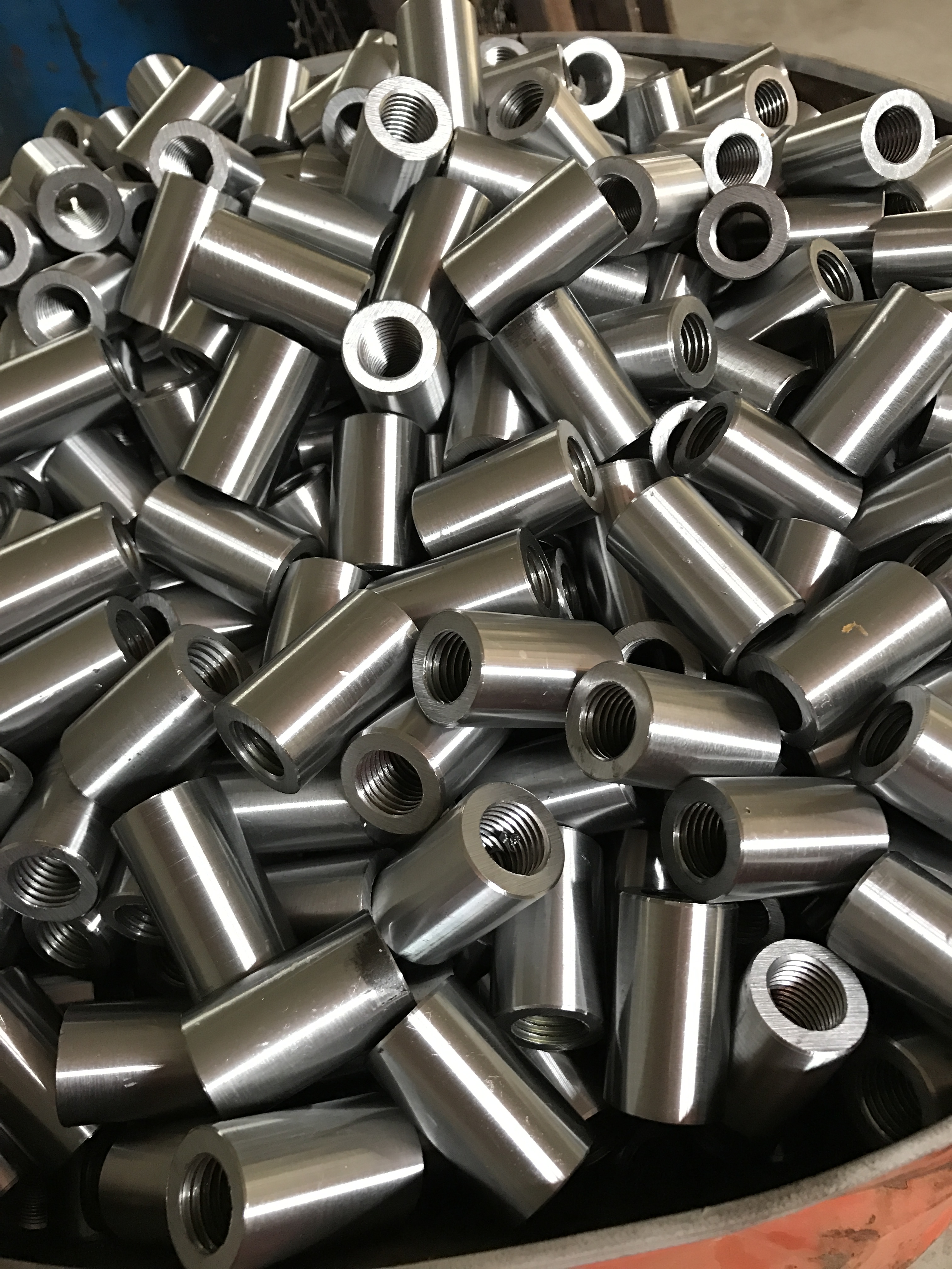
Selecting a rebar coupler at the execution stage comes down to four values that must agree with the rebar schedule and with the threading equipment on site: thread pitch and thread form, coupler outer diameter (OD), coupler length, and material grade. A coupler is not interchangeable across bar sizes, and a model number on its own does not confirm mechanical fit.
For mechanical splices in the 16–40 mm range, model designations follow the nominal rebar diameter — model 16 for 16 mm bar through model 40 for 40 mm bar. Within that series, Cangzhou Bartech Construction Material Co., Ltd. documents coupler outer diameters from 24 mm to 59 mm and coupler lengths from 42 mm to 95 mm, with thread forms such as M16.5×2.5 and M25.6×3.0 machined on a 60-degree thread angle. The same series is processed on CBT40A, CBT40L and 40AO threading machines, which cover 16–40 mm rebar with a maximum threading length of 95 mm.
This guide is written for the buyer who has already decided on mechanical splicing and now has to lock a part number, a material grade and a tooling set. That is the stage where an unverified OD or a short thread length turns into a site delay rather than a design discussion.
Problem Definition: What Goes Wrong When a Model Is Chosen by Size Alone
Most coupler selection errors are not caused by choosing the wrong connection technology. They happen one level lower, in the parameter match between the coupler, the prepared bar end and the machine that prepares it. Four mismatches account for most of them.
- Thread mismatch. The thread callout is a machining instruction, not a label. In this series the callouts include M16.5×2.5 for the model 16 coupler and M25.6×3.0 for the model 25 coupler. If the pitch or the 60-degree thread form does not match the threading head and the coupler's internal thread, the joint either will not assemble or will assemble without full engagement.
- OD mismatch. Coupler outer diameter runs from 24 mm to 59 mm across the series. An OD chosen only for bar capacity may fail at the congested detail, where concrete cover and tool clearance are already tight.
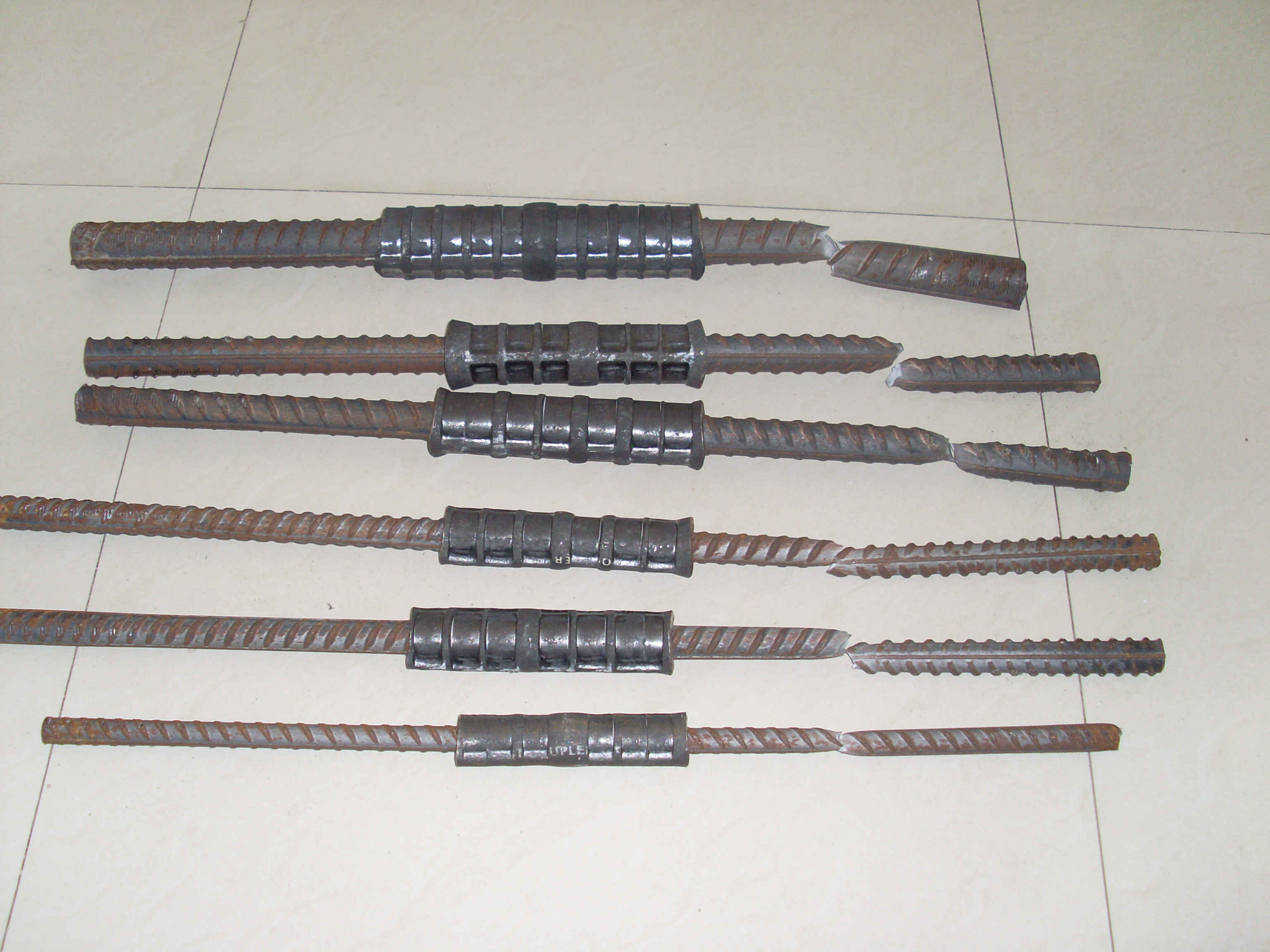
- Length mismatch. Coupler length runs from 42 mm to 95 mm. Length determines how much thread each bar end can engage, and therefore whether the two bar ends can meet inside the sleeve. This is the documented field risk: a connection is not properly made when the rebar ends are not wrenched into the middle of the coupler. The stated control method is to thread the bar end to the correct length and wrench both bar ends until they meet each other inside the coupler.
- Material mismatch. Carbon steel 45#, alloy steel 40CR, Q355B for pressing couplers, and alloy steel 40CR for ONE-TOUCH couplers are used across different coupler types. Substituting one grade for another changes the connection system, not only the cost.
A quieter fifth failure appears after the first shipment. Repeat orders are placed against a part number that no longer carries the original thread, OD and length values, and the substitution is only detected when a bar end will not seat.
Industry Background: Why Parameter-Level Selection Became a Buyer Task
The global rebar coupler market was valued at USD 1.82 billion in 2025 and is projected to reach USD 3.47 billion by 2034, a CAGR of 7.4% (Dataintelo). Building construction accounted for 47.6% of total revenue in 2025, and Asia Pacific contributed approximately 41.3% of global revenue in the same year. Tapered thread couplers held the largest product-type share at 38.2% in 2025, with parallel thread couplers following closely behind.
Two things follow from that structure. First, the largest demand sits in building construction and in Asia Pacific, where imported couplers and machines are often combined with local fabrication practice — precisely the situation in which thread and OD conventions must be confirmed rather than assumed. Second, because parallel thread systems sit close behind the leading type, project teams increasingly compare internal thread geometry between suppliers instead of treating “coupler” as one category.
On the compliance side, mechanical rebar splices are governed by international standards including ISO 15835, ASTM A615 and BS 8110, which in the EU is often replaced by Eurocode 2. Those standards set splice performance requirements; they do not fix a coupler's internal thread, outer diameter or length. Those values stay at project and supplier level, which is why they have to be locked model by model.
Detailed Solution: The Four Parameters That Define a Coupler Model
1. Thread Pitch and Thread Form
Thread pitch is the axial distance between adjacent thread crests and is written inside the thread callout — M16.5×2.5 for the model 16 coupler, M25.6×3.0 for the model 25 coupler. Two features of the callout deserve attention during selection. The first number sits slightly above the nominal bar diameter, so the thread designation and the model number are not the same value; the thread callout is the machining-level specification. The second number is the pitch, which has to match both the threading head or roller set that prepares the bar end and the internal thread of the coupler.
Thread form matters as much as pitch. This series is machined on a 60-degree thread angle. Because both the coupler and the bar end are cut to a defined thread form, pitch and angle should be treated as a single specification; confirming pitch without confirming the 60-degree angle leaves the joint only partly defined.
2. Outer Diameter (OD)
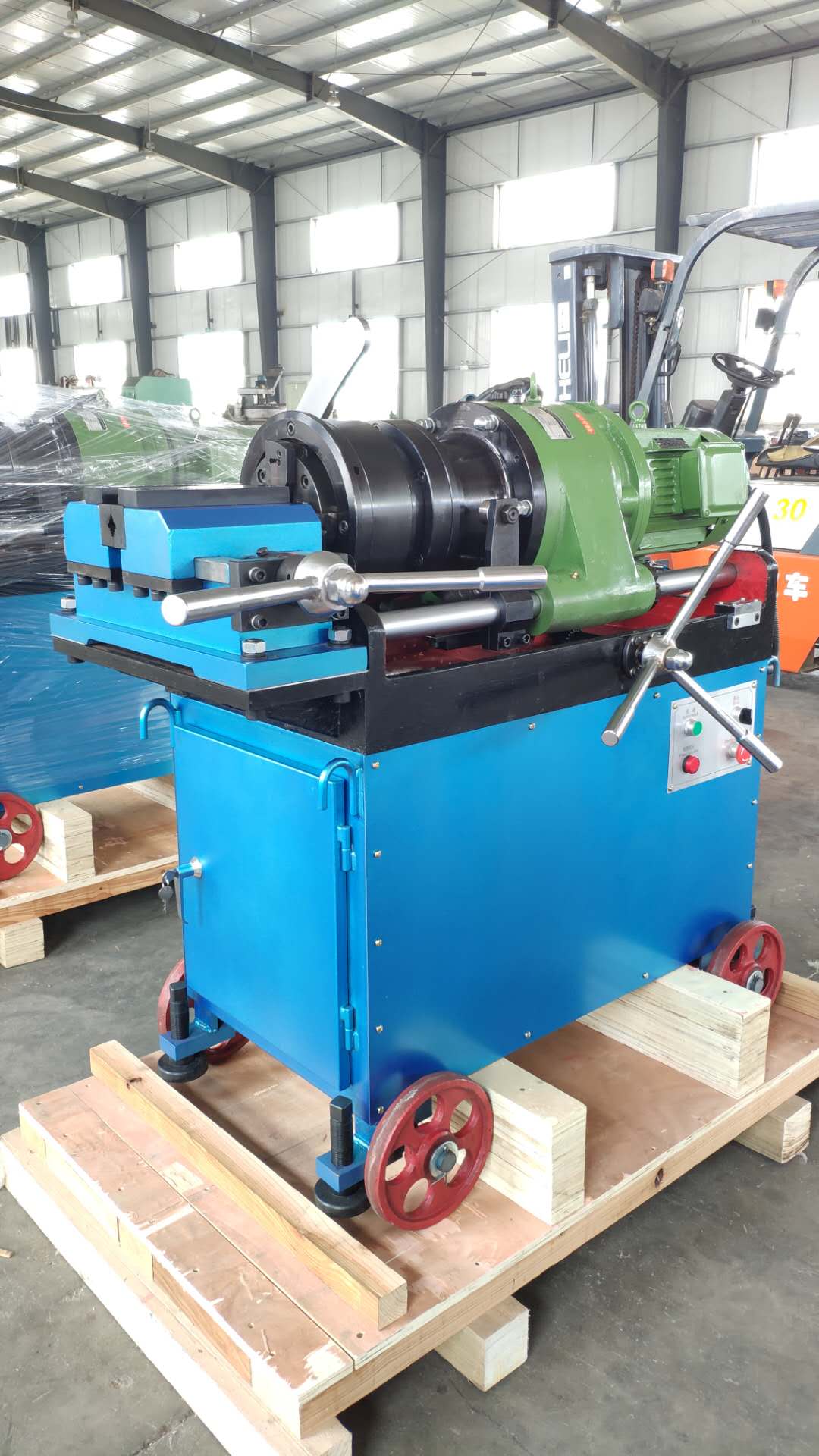
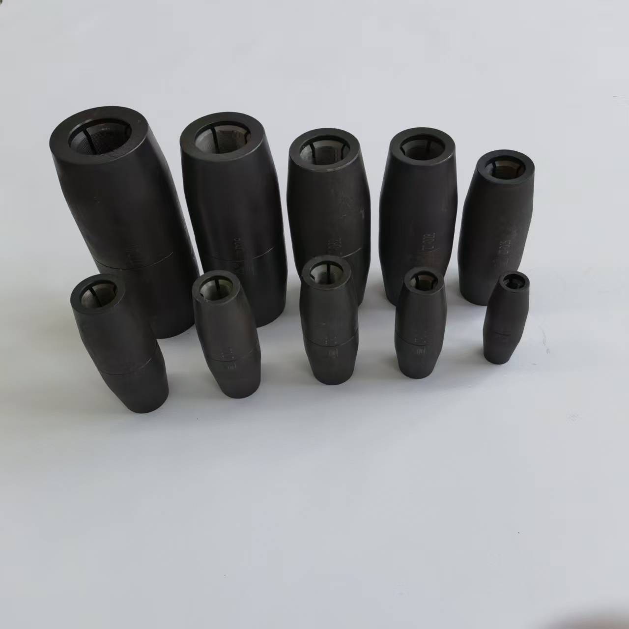
Across the 16–40 series, documented coupler outer diameters range from 24 mm to 59 mm. OD grows with bar capacity, which makes it the parameter most likely to collide with site conditions: reinforcement congestion at column and beam junctions, specified concrete cover, and the clearance the installation tool needs around the bar. On many projects OD is checked against the drawing after the model is chosen, not before. In congested pours, that order is worth reversing.
3. Coupler Length
Coupler lengths in the series run from 42 mm to 95 mm. Length sets how much thread each bar end can engage and how much load-transfer path exists inside the sleeve. It also interacts directly with tooling. Documented threading capacity in this line-up includes a maximum threading length of 95 mm for the series, and a documented configuration of 90 mm with a block or 150 mm without a block. Because those figures describe different machine configurations, the threading length for a specific model should always be confirmed against the machine actually quoted.
4. Material Grade
Material is chosen together with the connection technology, not independently of it. In this series the documented pairing is carbon steel 45# and alloy steel 40CR for rolled-thread couplers, Q355B for pressing couplers, and alloy steel 40CR for ONE-TOUCH couplers. A change of material without a change of connection type produces a coupler that may look identical and behave differently, which is why the material grade belongs on the purchase specification next to the thread callout.
Reading Model Designations 16 Through 40
Model designations in this series are the nominal rebar diameter: 16, 18, 20, 22, 25, 28, 32, 36 and 40. The model tells you which bar the coupler is dimensioned for. It does not tell you thread pitch, OD, length or material. Those four values are confirmed separately, which is the purpose of the parameter table below.
| Selection parameter | Documented value for the series |
|---|---|
| Model designations | 16 through 40 (nominal rebar diameter) |
| Matching rebar range | 16–40 mm |
| Thread angle | 60-degree thread angle |
| Thread callout examples | M16.5×2.5 (model 16); M25.6×3.0 (model 25) |
| Coupler outer diameter | 24 mm to 59 mm across different models |
| Coupler length | 42 mm to 95 mm across different models |
| Material for rolled (parallel) thread couplers | Carbon steel 45#; alloy steel 40CR |
| Material for pressing couplers | Q355B |
| Material for ONE-TOUCH couplers | Alloy steel 40CR |
| Threading machine models | CBT40A, CBT40L, 40AO |
| Machine rebar processing range | 16 mm to 40 mm |
| Maximum threading length | 95 mm |
Step-by-Step: Locking a Coupler Model for a Project
- Read the bar schedule first, not the coupler catalog. Match bar diameter to the model number from 16 through 40, and record the bar grade, because grade feeds the material decision.
- Confirm the connection system. Parallel (rolled) thread, upset forged, cold pressing and one-touch systems use different couplers and different site equipment. Material follows this decision: 45# and 40CR for rolled thread, Q355B for pressing, 40CR for ONE-TOUCH.
- Fix the thread specification. Record the thread callout and pitch, for example M16.5×2.5 or M25.6×3.0, and confirm the 60-degree thread angle with both the coupler supplier and the threading head supplier before any bar is cut.
- Check OD against the drawing. Compare coupler OD, which sits between 24 mm and 59 mm across the series, with cover, congestion and tool clearance at the most congested detail.
- Set coupler length against thread engagement. Length runs from 42 mm to 95 mm in the series; the required engagement has to be achievable with the threading length the machine can actually produce.
- Write the material callout on the order. State 45#, 40CR, Q355B or one-touch 40CR explicitly rather than relying on the model number to imply it.
- Match the machine to the model. CBT40A, CBT40L and 40AO cover 16–40 mm rebar with a maximum threading length of 95 mm. Documented shared specifications for the threading machine range include a main motor of 5.5 kW or 7.5 kW at 1450 r/min, rated voltage 380 V / 50 Hz, air clamping pressure of 0.4–0.8 MPa, a 0.12 kW water pump at 1450 r/min, and a speed ratio of 1:23 (quick) or 1:29 (slow). Documented unit weights and dimensions across the range are 680 kg and 860 kg, with overall dimensions of 1820×815×1100 mm and 1950×700×1120 mm.
- Lock the four values as a repeatable part number. Once thread, OD, length and material are confirmed, record them as the project standard so later shipments match the first. Thread protection belongs in that standard as well, since a damaged thread on stored bar is re-worked at site cost.
- Validate before shipment. The stated acceptance criterion is a pre-shipment test. Combine it with the operation documents and installation training that accompany the order, and verify the specific field risk: the two bar ends must be wrenched until they meet at the middle of the coupler.
Use Cases: Where Model-Level Matching Decides the Outcome
High-rise building cores and transfer levels
Bar congestion is at its worst where columns, walls and beams meet, so coupler OD and length are checked against cover and tool clearance before the pour sequence is fixed. Mechanical splicing is documented for high buildings, and comparison data records installation speed 3–5 times faster than lap tying, with 50–70% lower cost.
Bridges, including cross-sea structures
Long, continuous reinforcement runs favour pre-fabricated, factory-threaded bar ends and couplers dimensioned for heavier bar sizes within the 16–40 mm range. Bridge projects are among the documented applications for this product line. Because site weather interrupts some connection methods but not others, pre-threading at the fabrication yard and wrenching on site is the practical sequence.
Metro and tunnel works
Tunnel segments and metro slabs leave little room for tools around the bar, so OD and length selection is driven by access rather than by capacity alone. Connection systems with a faster, more direct make-up step suit these conditions, and the materials used for those systems differ from standard rolled-thread couplers.
Airports and high-railway stations
These are schedule-driven projects with long, repetitive reinforcement runs. Documented applications for this coupler line include airport projects and high-railway stations. In that setting, the value of locking thread, OD, length and material early is repeatability: every subsequent batch matches the first, and installation crews work to a single method statement.
Comparison Table: Materials, Equipment and Connection Methods
Material is the first decision that cannot be separated from connection type. The table below lists only the material and system pairings documented for this coupler series.
| Material | Coupler type in the series | Selection note |
|---|---|---|
| Carbon steel 45# | Rolled (parallel) thread coupler | Carbon steel option for the rolled-thread connection system |
| Alloy steel 40CR | Rolled (parallel) thread coupler | Alloy steel option within the same rolled-thread system |
| Q355B | Pressing coupler | Grade paired with the cold pressing connection system |
| Alloy steel 40CR | ONE-TOUCH coupler | Grade used for the one-touch connection system |
The second comparison set concerns tooling. Coupler selection and machine selection are one decision, because the thread the coupler receives has to be produced by the machine on site.
| Threading machine model | Rebar processing range | Maximum threading length |
|---|---|---|
| CBT40A | 16–40 mm | 95 mm |
| CBT40L | 16–40 mm | 95 mm |
| 40AO | 16–40 mm | 95 mm |
Finally, the connection method itself is part of the comparison. The figures below are documented manufacturer comparison data for these connection systems, not independent third-party benchmarks.
| Decision factor | Versus traditional lap tying | Versus welding |
|---|---|---|
| Installation speed | 3–5 times faster than lap tying | 2–4 times faster than welding after factory pre-threading |
| Cost impact | Documented at 50–70% lower cost | 50% lower worker cost |
| Weather sensitivity | Not stated in the comparison data | Not affected by weather |
| Quality control | Easier quality control, quick installation | Easier quality control, easy installation |
FAQ: Model Selection, Compliance and Ordering
Which standards and certifications apply to a rebar coupler model?
Mechanical rebar splices are governed by international standards including ISO 15835, ASTM A615 and BS 8110, which in the EU is often replaced by Eurocode 2. These standards define splice performance requirements rather than the internal dimensions of a specific coupler model, so thread, OD, length and material still have to be verified against the project specification. For documentation, Cangzhou Bartech Construction Material Co., Ltd. holds CE certification Nr. SC-PSC-4-2025-12-14, valid until 2030, and ISO9001:2015 certificate 31623Q10713R1S.
Can coupler outer diameter, inner diameter and thread be customized?
Yes. Customization is available for coupler outer diameter, inner diameter and thread, and OEM production is offered. Customization matters when a project uses a non-standard thread callout, or when the standard OD range of 24–59 mm does not resolve a tight cover condition. The processing side supports it: rebar processing range is 16–40 mm with a maximum threading length of 95 mm.
What drives the cost of one coupler model?
Cost at model level is driven by the parameters in this guide: material grade (carbon steel 45#, alloy steel 40CR, Q355B for pressing couplers, or alloy steel 40CR for ONE-TOUCH), the OD and length that set steel weight per unit, thread machining time, and order quantity. Commercial terms are FOB or CIF. Against traditional methods, documented comparison data records installation speed 3–5 times faster than lap tying at 50–70% lower cost, and 50% lower worker cost versus welding.
How can a buyer validate a selected model before the full order?
Validation runs through the pre-shipment test, which is the stated acceptance criterion, together with the operation documents and training supplied for correct installation. The check should cover both the coupler dimensions and the way bar ends are threaded and seated, because the documented field risk is a connection not properly made when the bar ends are not wrenched into the middle of the coupler.
What are the lead time, MOQ and payment terms?
Monthly production capacity is 300,000 units, and typical production lead time is 7–30 days depending on order quantity. There is no minimum order quantity for stock couplers. Payment terms are 30% TT prepayment to confirm the order, with 70% by TT after goods are ready and before shipment; delivery terms are FOB or CIF. To confirm a model against your rebar schedule, send the bar size, thread callout, OD, length and material requirement to sales@chinabartech.cn or WhatsApp +86 13785685215, and ask for a sample or a model-matched quotation.
Conclusion
Coupler selection is a four-value lock: thread pitch and thread form, outer diameter, length and material. Each value has to be traceable to the bar schedule, the drawing and the threading machine, and each has to be written into the part number so that repeat orders arrive identical to the first shipment. Two checks decide most projects: whether the 60-degree thread and its pitch match the tooling that prepares the bar end, and whether the bar ends can meet at the middle of the coupler at the length actually ordered.
Cangzhou Bartech Construction Material Co., Ltd. has supplied rebar couplers and rebar threading machines since 2008 from Qing County, Cangzhou City, Hebei Province, China, exporting to Asia, the Middle East and South America, including Vietnam, Malaysia, Kuwait, Qatar, UAE, Saudi Arabia and Mexico. Production runs through a three-stage quality control process: material test reports, 10% in-line production testing and 100% final appearance inspection. Monthly capacity is 300,000 units with typical lead times of 7–30 days, no minimum order quantity for stock couplers, and online technical after-sales support. Full details are available at www.chinabartech.cn.
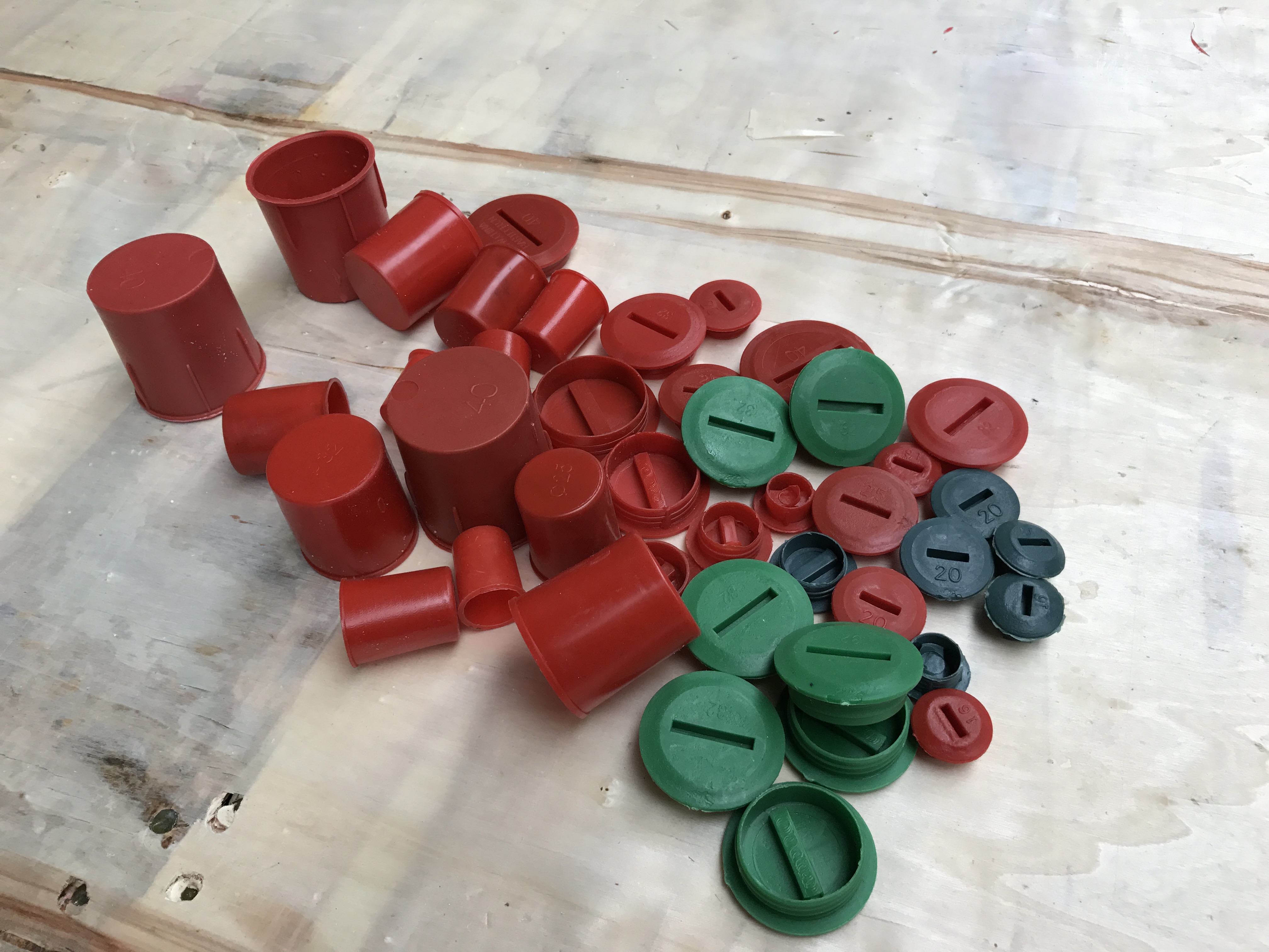
Model match before you order
Send your rebar schedule with bar size, thread callout, required OD and length, and material grade. Bartech will confirm the matching model from the 16–40 series, the threading machine configuration, and the pre-shipment test arrangement.
Email: sales@chinabartech.cn | Tel / WhatsApp: +86 13785685215 | Web: www.chinabartech.cn
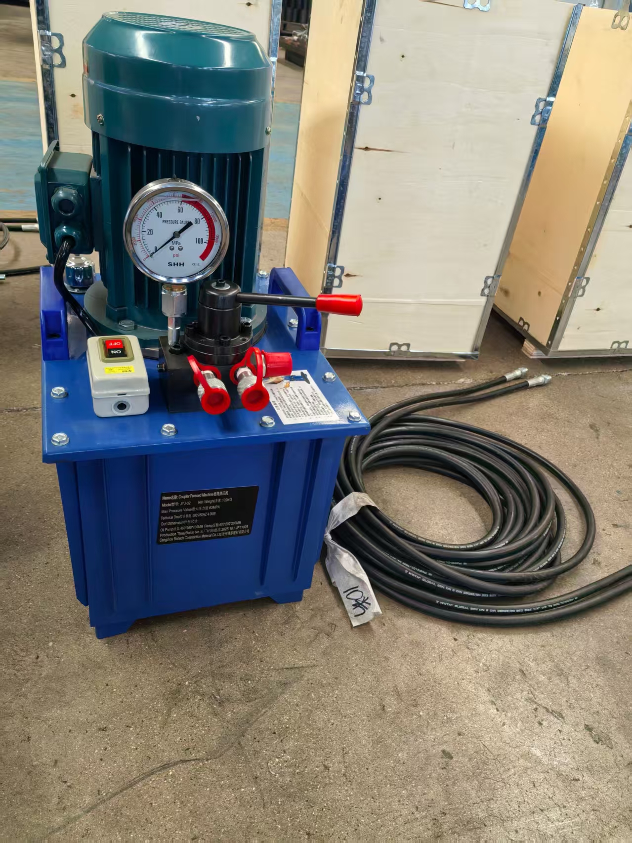
Have Questions or Need More Details?
Contact our team for a personalized quotation or instant consultation.
Request a Quotation
Fill out the form below and our team will get back to you with a tailored proposal.
WhatsApp Direct Chat
Prefer to chat in real-time? Message us on WhatsApp for instant assistance & quick answers.
- Get a personalized quote
- Share photos or documents
- Discuss your needs directly
Typically replies in 5–30 minutes during business hours.