
What Do Rebar Coupler Model Numbers Mean? A Beginner’s Guide to Sizes, Threads, and Materials
A rebar coupler model number — 16, 18, 20, 22, 25, 28, 32, 36 or 40 — is the nominal diameter, in millimetres, of the reinforcing bar the coupler is designed to join. It is not the outside diameter of the coupler, and on its own it does not tell you the thread.
Reading a coupler code properly requires three layers: the size number (which bar it fits), the thread designation (how the bar end is prepared, for example M16.5×2.5), and the body envelope (outside diameter × length) plus a material grade. This guide decodes all three using the published catalogue values of Cangzhou Bartech Construction Material Co., Ltd. (Bartech), a China-based supplier of rebar couplers and rebar threading machines that has exported mechanical connection products since 2008.
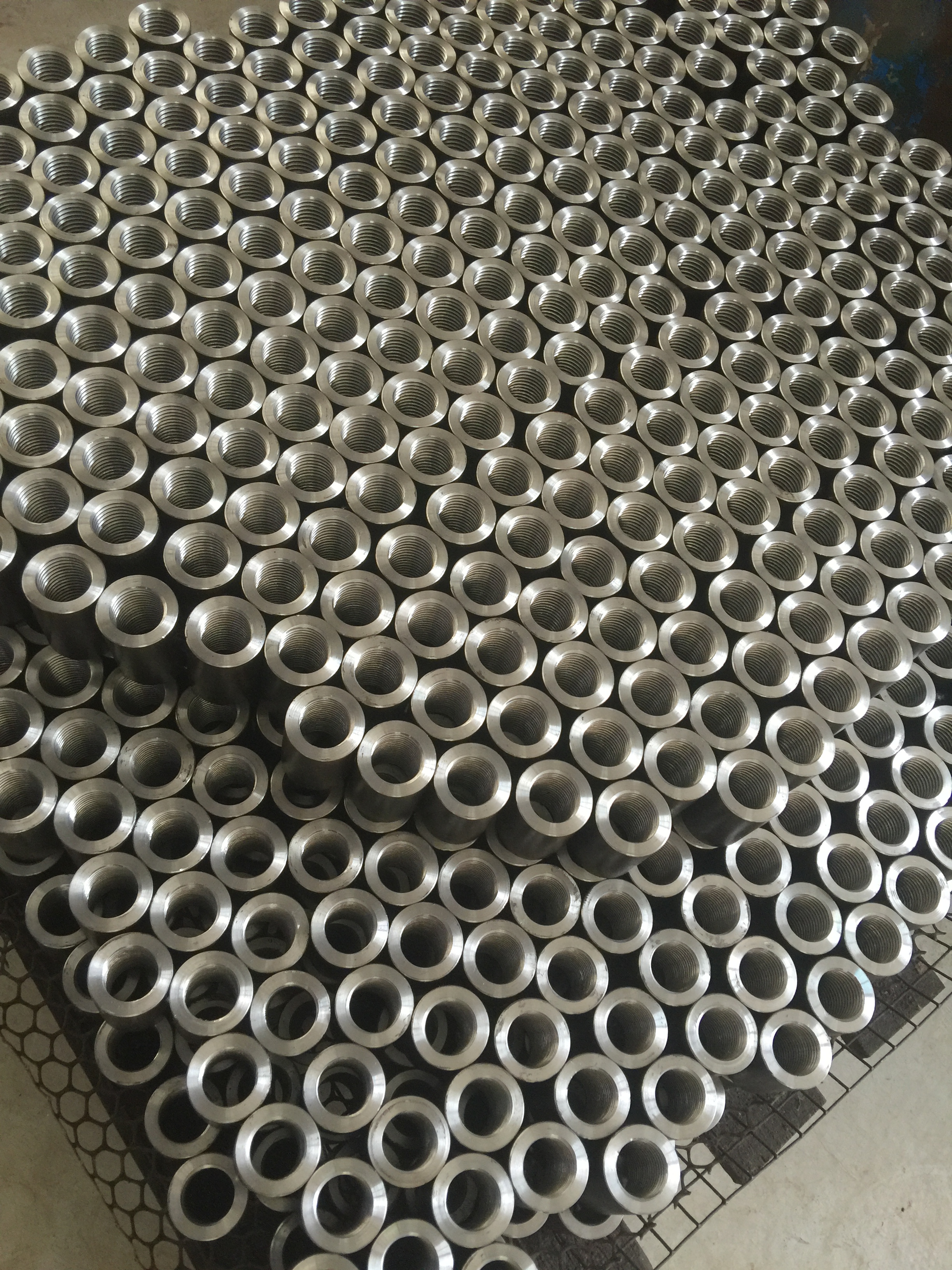
The problem: one number, several different couplers
Most confusion begins when a size number is treated as a complete specification. In the Bartech range, size 16 exists as four different parts:
- a rolling (parallel thread) rebar coupler, thread M16.5×2.5, outside diameter 24 mm, length 42 mm;
- an upsetting coupler, thread M20×2.5, outside diameter 26 mm, length 40 mm;
- a cold pressing coupler, outside diameter 30 mm, length 110 mm, wall thickness 4.5 mm;
- a one-touch coupler covering bars of 11–16 mm, outside diameter 35 mm, length 100 mm.
All four are “size 16”, and none is interchangeable with the others, because each assumes a different bar-end condition: a rolled thread, an enlarged (upset) bar end, a pressed sleeve, or a quick-connection body tightened with torque. Ordering “16 mm couplers” without the family and the thread code is the most common reason a delivery does not fit the site.
The same trap appears in reverse. A coupler with a 30 mm outside diameter is not a 30 mm coupler: it is the rolling coupler for 20 mm bar, and it is also the outside diameter of the pressing coupler for 16 mm bar. Outside diameter belongs to the envelope layer, never to the model layer.
Industry background: where the numbers come from
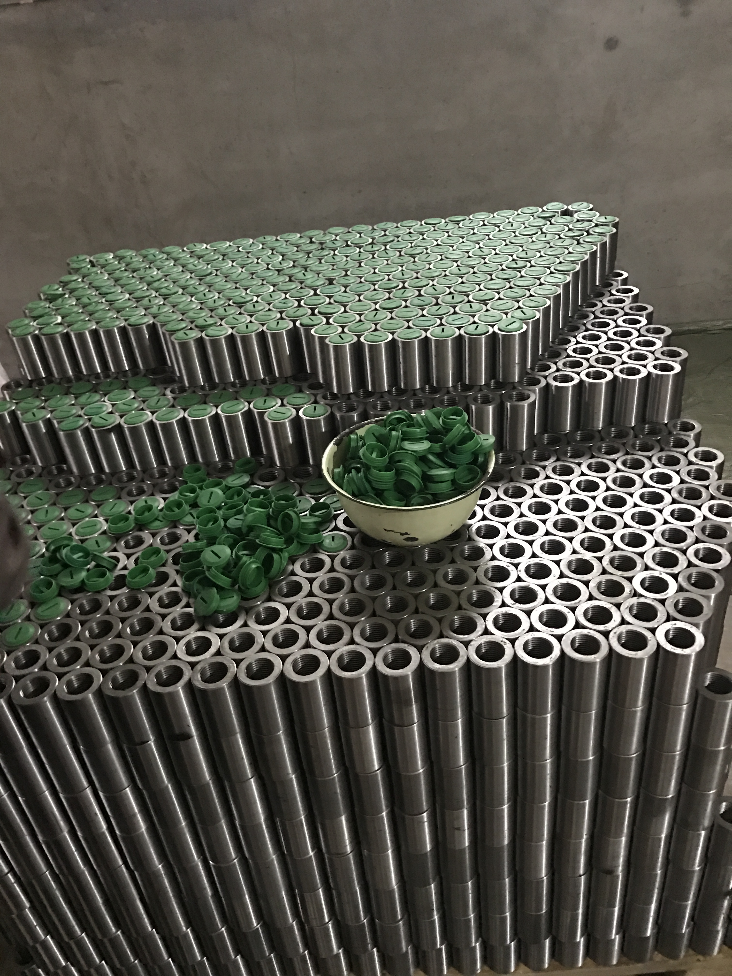
A rebar coupler is the hardware half of a mechanical splice. The bar end is prepared — thread rolled onto the bar, the bar end upset, or the coupler pressed onto the bar — and the coupler joins two prepared ends so the splice can transfer load.
The naming convention follows the bar, not the part. Reinforcement is specified by nominal diameter (16, 20, 25, 32 and so on), so coupler catalogues reuse the same digits to state “this part is for that bar”. Everything else in the code is a manufacturing detail that only becomes meaningful once the family is known: the thread diameter and pitch depend on how the bar end is prepared, and the body outside diameter depends on how much wall the connection method needs.
International standards define what a splice must achieve, not what a part number should look like. ISO 15835-1:2018 specifies requirements for couplers used for mechanical splices of steel reinforcing bars, including static, fatigue and reverse-loading applications as described on the official ISO page; ISO 15835-2:2018 specifies the test methods; ISO 15835-3:2018 specifies rules for certification and self-evaluation. Market research on mechanical splices also lists ASTM A615 and BS 8110 among the frameworks buyers check. None of these documents gives “model 20” a universal thread or length, which is why the drawing of the supplier you are buying from is the only reliable reference.
Layer 1: the size number is the bar diameter
The digit is the nominal bar size in millimetres. Model 20 is for 20 mm bar; model 32 is for 32 mm bar. The catalogue covers nine steps: 16, 18, 20, 22, 25, 28, 32, 36 and 40.
Two things are worth noting. The steps are not perfectly even — 16, 18, 20, 22, then a jump to 25 — because bar sizes are standardised rather than the couplers. And the one-touch range is slightly different again: it adds an 11–16 mm size and a 29 mm size alongside the standard steps.
The practical benefit is simple: if you know the bar size, you already know the first layer of the model number. If you know only the coupler’s outside diameter, you know nothing about the bar size.
Layer 2: the thread code shows how the bar end is prepared
Thread designations follow the metric pattern M + nominal thread diameter + pitch. M16.5×2.5 therefore means a metric thread of 16.5 mm nominal diameter with a 2.5 mm pitch. Pitch is the axial distance between adjacent thread crests, so a coarser pitch appears on larger bars where more material is available.
Every thread in this catalogue also carries a 60° thread angle — the included angle of the V-shaped thread profile. It appears in the specification because the bar-end thread and the coupler thread must share the same geometry; a thread produced to a different profile will not seat correctly even when diameter and pitch appear to match.
Rolling (parallel thread) couplers: thread just above bar size
In the rolling series, the thread diameter sits a fraction above the bar: 16 → M16.5×2.5, 18 → M18.5×2.5, 20 → M20.5×2.5, 22 → M22.5×2.5, 25 → M25.6×3.0, 28 → M28.6×3.0, 32 → M32.6×3.0, 36 → M36.6×3.0, 40 → M40.2×3.0. The pitch is 2.5 mm from size 16 to 22 and 3.0 mm from size 25 to 40.
Upsetting couplers: thread well above bar size
The upsetting series looks completely different, because the bar end is enlarged before threading, so the thread is produced on a larger diameter: 16 → M20×2.5, 18 → M22×2.5, 20 → M24×3.0, 22 → M27×3.0, 25 → M30×3.5, 28 → M33×3.5, 32 → M36×4.0, 36 → M39×4.0, 40 → M45×4.0.
Pressing and one-touch couplers: no thread code at all
Cold pressing (cold extrusion) couplers are specified by bar size plus outside diameter, length and wall thickness, because there is no thread — the coupler is compressed onto the bar with a pressing machine. One-touch (quick connection) couplers are specified by bar size plus outside diameter and length, and are tightened with an electric torque wrench instead of being threaded on site.
Layer 3: outside diameter and length are the envelope
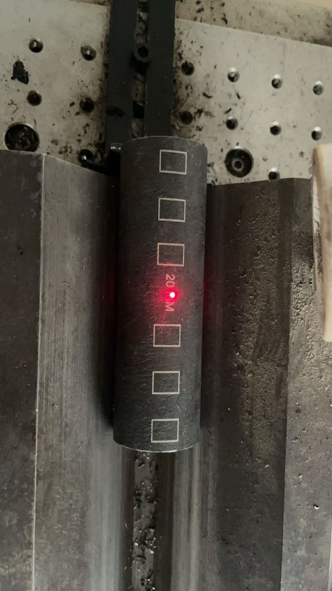
Body dimensions decide whether the splice actually fits — cover, bar spacing, formwork and congestion at a beam-column joint all depend on them. In the rolling series the outside diameter runs from 24 mm at size 16 to 59 mm at size 40, with lengths from 42 mm to 95 mm. Upsetting bodies are shorter and slightly larger in diameter for the same bar: 26 × 40 mm at size 16 rising to 62 × 90 mm at size 40. Pressing bodies are the longest in the range, from 30 × 110 mm with a 4.5 mm wall at size 16 up to 70 × 240 mm with an 11.0 mm wall at size 40. One-touch bodies run from 35 × 100 mm for the 11–16 mm size to 83 × 200 mm at size 40.
There is no formula that converts a bar size into a body dimension. These are catalogue values, so they should be read from the drawing rather than inferred from the model number.
Material grades: 45#, 40CR and Q355B
Bartech lists two material options for threaded couplers and a third for pressed bodies:
- Carbon steel 45# — the standard option for rolling and upsetting couplers.
- Alloy steel 40CR — the alternative for rolling and upsetting couplers, and the specified material for one-touch couplers.
- Carbon steel Q355B — the material listed for cold pressing couplers.
The company’s published material notes also cite S45C with tensile strength above 600 MPa and 40Cr at roughly 980 MPa. Material is not encoded in the model number, so it must be written separately on the order together with the connection family and thread.
Step-by-step: decoding a rebar coupler code in five steps
- Read the size digits. 25 means a 25 mm nominal bar — nothing more at this stage.
- Identify the family. Rolling, upsetting, cold pressing or one-touch. The family defines what the bar end must look like before the coupler can be installed.
- Read the thread. M + nominal diameter + pitch, then confirm the 60° profile. If no thread code exists, the part is a pressed or mechanically locked type.
- Check the envelope. Outside diameter, length and, for pressing couplers, wall thickness against cover and spacing.
- Confirm material and documents. 45#, 40CR or Q355B, plus the test documentation the project specification requires.
| Model number (= bar size) | Rolling coupler: thread / OD × length | Upsetting coupler: thread / OD × length | Cold pressing coupler: OD × length / wall | One-touch coupler: OD × length |
|---|---|---|---|---|
| 16 | M16.5×2.5 / 24 × 42 mm | M20×2.5 / 26 × 40 mm | 30 × 110 mm / 4.5 mm | 40 × 106 mm (11–16: 35 × 100 mm) |
| 18 | M18.5×2.5 / 27 × 45 mm | M22×2.5 / 29 × 44 mm | 34 × 120 mm / 5.4 mm | 46 × 123 mm (shared 18/20 size) |
| 20 | M20.5×2.5 / 30 × 50 mm | M24×3.0 / 32 × 48 mm | 36 × 120 mm / 5.5 mm | 46 × 123 mm (shared 18/20 size) |
| 22 | M22.5×2.5 / 33 × 54 mm | M27×3.0 / 36 × 52 mm | 40 × 132 mm / 6.4 mm | 51 × 133 mm |
| 25 | M25.6×3.0 / 38 × 62 mm | M30×3.5 / 40 × 60 mm | 45 × 150 mm / 7.4 mm | 56 × 143 mm |
| 28 | M28.6×3.0 / 42 × 68 mm | M33×3.5 / 44 × 66 mm | 50 × 168 mm / 8.0 mm | — (29 mm size: 65 × 166 mm) |
| 32 | M32.6×3.0 / 48 × 76 mm | M36×4.0 / 50 × 72 mm | 56 × 192 mm / 9.0 mm | 70 × 170 mm |
| 36 | M36.6×3.0 / 53 × 84 mm | M39×4.0 / 56 × 80 mm | 63.2 × 220 mm / 11.3 mm | 78 × 190 mm |
| 40 | M40.2×3.0 / 59 × 95 mm | M45×4.0 / 62 × 90 mm | 70 × 240 mm / 11.0 mm | 83 × 200 mm |
All threads listed above carry the 60° thread angle. Body dimensions and thread designations are Bartech catalogue values; other manufacturers may use different thread diameters, pitches and body sizes for the same bar size.
Use cases: the same digits under different site conditions
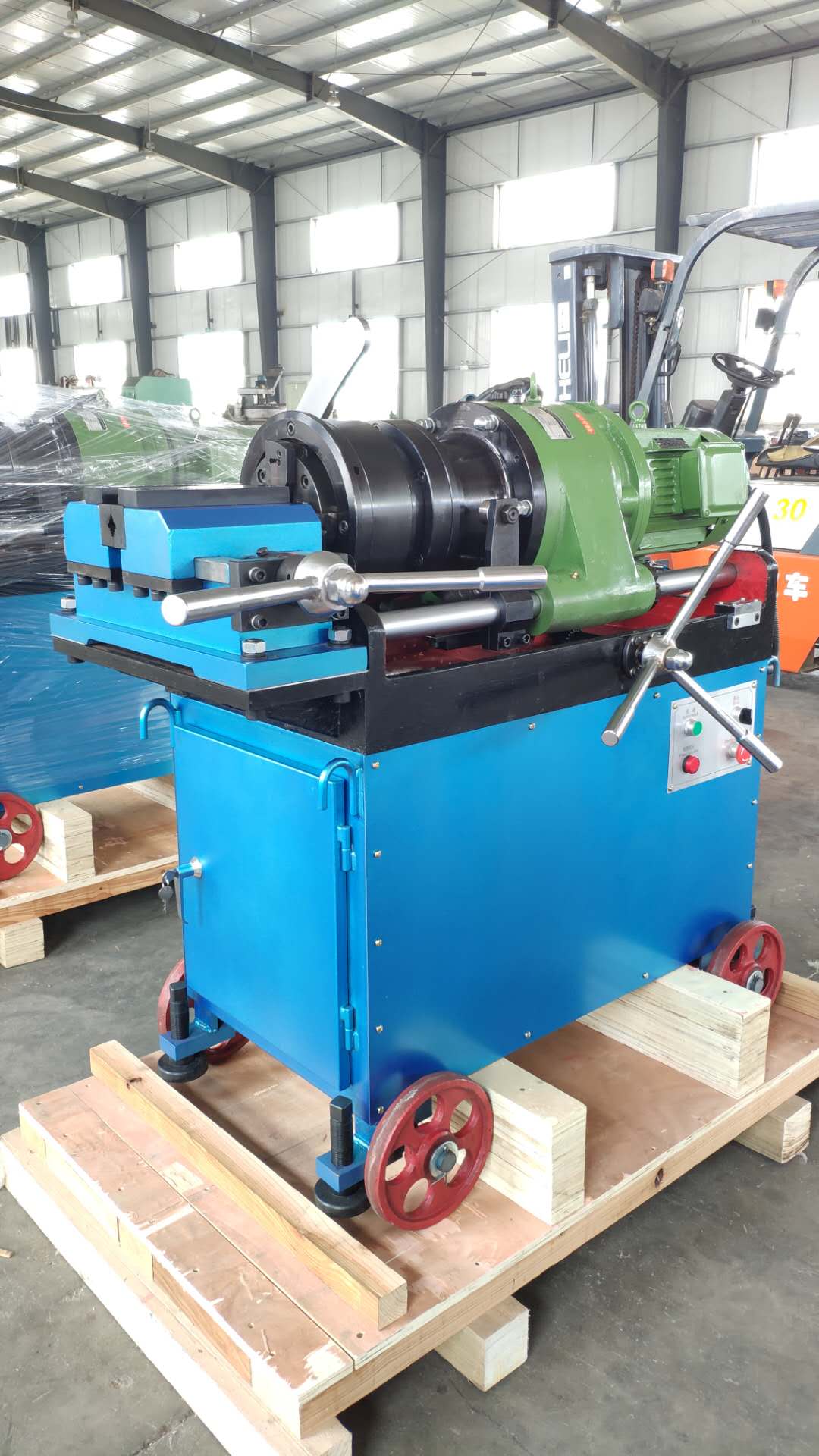
High-rise building construction. Rolling couplers in sizes 16 to 32 are installed with rebar thread rolling machines such as the CBT40A, CBT40L, 40AO or 40MO, all of which cover 16–40 mm bar. The thread is rolled directly onto the bar end, so the parts are matched to a threading machine on site rather than to an upsetting unit.
Large bridges and heavy foundations. Where the largest bars are involved — 32, 36 and 40 — the upsized thread of the upsetting series is paired with the 36S or 50S upsetting machine, and the thread designation on the order must match the enlarged bar end rather than the original bar diameter.
Metro, tunnel and precast work. Pressing couplers (16–40 mm) are installed with the CBT32 pressing machine, which covers 16–32 mm bar, while one-touch couplers are tightened with the BOC 8-32 or BOC 8-42 electric torque wrench. On congested sections, the shorter body of a one-touch part can matter more than the thread code.
Standard supply programmes. Volume projects usually standardise on a small set of model numbers. Construction enterprise clients in Kuwait order 400,000 rebar couplers per year for outdoor construction work, and a project in Vietnam uses 500,000 couplers per year across tall building and railway station construction.
Comparison table: what each family’s number actually means
| Coupler family | Size numbers in catalogue | Jointing method | Example at size 20 | Material options | Matching equipment |
|---|---|---|---|---|---|
| Parallel thread rolling (rolled thread) | 16–40 | Metric thread rolled onto the bar end, 60° profile | Thread M20.5×2.5; 30 × 50 mm | 45# carbon steel; 40CR alloy steel | CBT40A, CBT40L, 40AO, 40MO threading machines (16–40 mm) |
| Parallel thread upsetting (upset forged) | 16–40 | Thread cut on an enlarged bar end, 60° profile | Thread M24×3.0; 32 × 48 mm | 45# carbon steel; 40CR alloy steel | 36S and 50S upsetting machines |
| Cold pressing (cold extrusion) | 16–40 | Pressed sleeve, no thread | 36 × 120 mm, 5.5 mm wall | Q355B carbon steel | CBT32 pressing machine (16–32 mm bar) |
| One-touch (quick connection) | 11–16 up to 40, plus a 29 mm size | Mechanical quick connection, tightened with torque | 46 × 123 mm (shared 18/20 size) | 40CR alloy steel | BOC 8-32 torque wrench (8–32 mm bar); BOC 8-42 torque wrench (12–40 mm bar, 16–32 coupler) |
Four decoding mistakes to avoid
- Reading the size number as outside diameter. A model 20 rolling coupler is 30 mm across; a model 16 pressing coupler is also 30 mm across.
- Reading the thread diameter as bar size. M45×4.0 belongs to a 40 mm bar in the upsetting series — it is not a 45 mm coupler.
- Assuming one thread per bar size. Size 20 is M20.5×2.5 when rolled and M24×3.0 when upset. Supplying the wrong one means the bar end cannot be prepared to match.
- Ordering from the model number alone. Body dimensions are catalogue data, not a standard formula, so the supplier’s drawing has to be checked for the exact size you are buying.
FAQ
Does the model number prove a coupler complies with ISO 15835 or ASTM A615?
No. A model number describes bar size, thread and body dimensions; it does not certify conformity. ISO 15835-1:2018 specifies requirements for couplers used for mechanical splices of steel reinforcing bars, ISO 15835-2:2018 specifies the test methods, and ISO 15835-3:2018 specifies rules for certification and self-evaluation. Buyers therefore check three separate items: the requirement standard named in the project specification, test reports produced to the applicable test method, and conformity or certification evidence. Bartech holds a CE certificate (Nr.SC-PSC-4-2025-12-14, issued 2025-12-04, valid to 2030-12-03) and an ISO 9001 certificate (31623Q10713R1S, valid to 2026-12-21); both should be read together with the model-specific drawing and test report for the size being ordered.
Can the thread or body dimensions behind a model number be customized?
Yes. Bartech offers OEM production and customization of coupler outer diameter, inner diameter and thread, with a monthly capacity of 300,000 pieces. This is exactly why a model number should always be confirmed on a drawing: a project that needs a non-standard thread or a shorter body receives a part that no longer matches the standard catalogue row for that bar size.
What is the minimum order quantity and payment basis?
For stock couplers there is no minimum order quantity. Delivery terms are FOB or CIF, payment is 30% TT prepayment to confirm the order with the remaining 70% by TT after the goods are ready and before shipment, and pre-shipment testing serves as the acceptance criterion.
How can a thread code be verified before a bulk order?
Request the drawing and the quality documents for the exact size: material test report, 10% production testing during the production line run, 100% appearance surface checking and pre-shipment testing. The drawing should state the thread designation, pitch, 60° profile, outside diameter and length, so the part can be checked against the bar-end preparation used on site. Online technical support is available after delivery.
How long does production take?
Lead time is 7–30 days depending on quantity. To start, send the bar size, coupler family, thread code (or drawing), material grade and quantity to sales@chinabartech.cn or WhatsApp +86 13785685215, and the matching model number can be confirmed before production begins.
Conclusion
A rebar coupler model number is a bar size, not a full specification. Read it in three layers: the digit gives the nominal bar diameter, the thread code gives the nominal thread diameter, pitch and 60° profile that the bar end must match, and the outside diameter and length give the envelope that decides whether the splice fits. Material — 45#, 40CR or Q355B — is a fourth, separate instruction on the order.
Once those layers are separated, the catalogue stops looking arbitrary: 16 to 40 is simply the bar range, M16.5×2.5 to M40.2×3.0 is the rolled thread family, M20×2.5 to M45×4.0 is the upset family, and pressing and one-touch parts drop the thread code because they do not use one.
Need the right model number for your bar size?
Send the bar size, connection family, thread code or drawing, material grade and quantity, and Bartech will confirm the matching coupler and the tooling that prepares the bar end.
CANGZHOU BARTECH CONSTRUCTION MATERIAL CO. LTD.
Website: www.chinabartech.cn
Email: sales@chinabartech.cn
Tel / WhatsApp: +86 13785685215
Address: Qing County, Cangzhou City, Hebei Province, China
Have Questions or Need More Details?
Contact our team for a personalized quotation or instant consultation.
Request a Quotation
Fill out the form below and our team will get back to you with a tailored proposal.
WhatsApp Direct Chat
Prefer to chat in real-time? Message us on WhatsApp for instant assistance & quick answers.
- Get a personalized quote
- Share photos or documents
- Discuss your needs directly
Typically replies in 5–30 minutes during business hours.