
Fiberglass Fabric for RTM Molds: A Technical Guide to High-Stiffness Composites
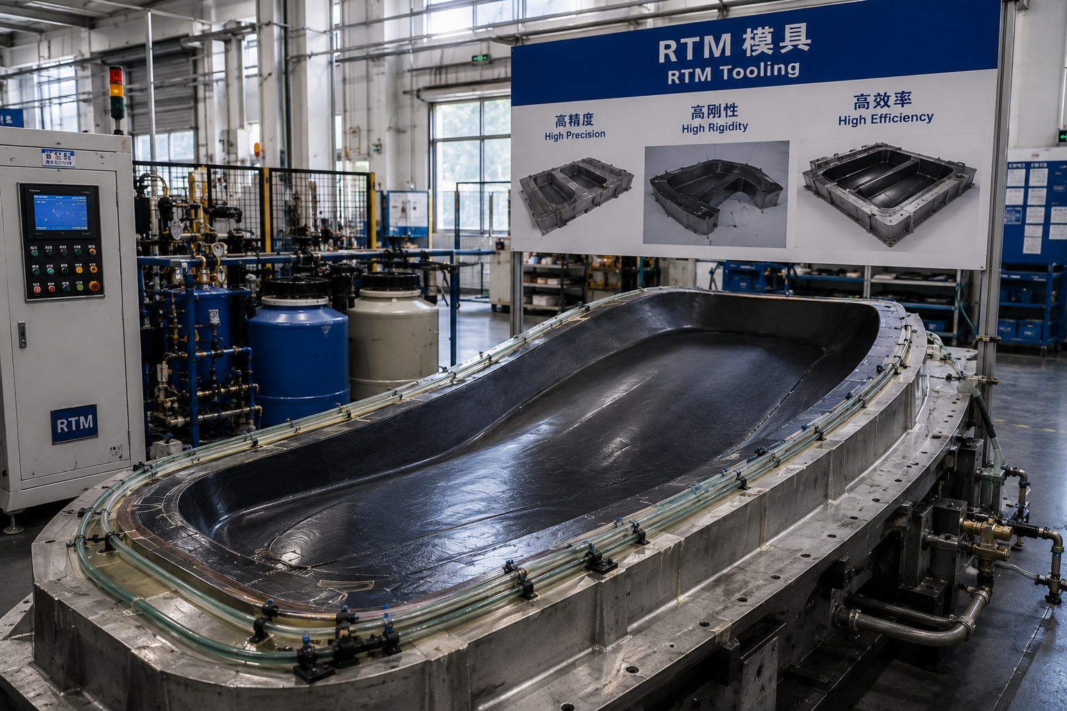
The RTM and composite tooling material stack: fiberglass fabric, multiaxial fabric, core mat and foam core — the reinforcement layers that determine mold stiffness, dimensional stability and tool life.
In RTM and VARTM mold construction, the fiberglass fabric in the tool laminate is a structural decision, not a consumable line item. The reinforcement architecture — woven E-glass, unidirectional, biaxial, triaxial or quadriaxial non-crimp fabric — governs how a mold behaves under high temperature, high pressure, vacuum integrity requirements and repeated thermal cycling. Specify the wrong reinforcement schedule and the tool loses dimensional stability long before it wears out.
This technical guide is written for composite engineers, tooling managers and procurement teams specifying reinforcement for resin transfer molding (RTM) and vacuum-assisted resin transfer molding (VARTM) tools. It explains what RTM mold laminates actually demand, how fiberglass fabric formats map onto those demands, the selection parameters that matter most — stiffness, surface quality, weight criticality — and how CINON Composites materials fit into a tooling build.
The Problem: Why RTM and VARTM Molds Lose Stiffness, Geometry and Vacuum Integrity
A resin transfer molding tool does not sit still. In composite tooling applications the operating conditions are defined by high temperature, high pressure, vacuum integrity and thermal cycling. The tool must simultaneously deliver dimensional stability, reduced tool weight and improved production efficiency, while meeting two hard requirements: vacuum resistance and heat distortion resistance.
Those requirements are laminate properties, and the laminate is built from reinforcement. When an RTM mold distorts, leaks vacuum or prints fiber texture through the part surface, the cause is usually traceable to the reinforcement schedule rather than to the injection equipment:
- Fiber crimp. Woven fabrics interlace warp and weft yarns. At the crossover points the fibers are crimped, which allows the laminate to move slightly under load. Multiaxial non-crimp fabrics are stitched rather than woven, so crimp is reduced and mechanical performance is improved.
- Moisture carried into the laminate. Multiaxial fiberglass fabrics are specified with a moisture content of less than 0.2%. Moisture that enters with the reinforcement becomes voids and surface defects after cure.
- Unbalanced fiber orientation. A tool that cures with fibers oriented in only one direction will distort in the other direction when it is thermally cycled. Unidirectional (0° or 90°), biaxial (0°/90° or +45°/−45°), triaxial and quadriaxial formats exist precisely to balance load distribution.
- Binder and sizing effects. Multiaxial fabrics are specified with combustible matter between 2.0% and 8.0%, a figure that reflects the stitching and binder content of the reinforcement and influences handling and resin wet-out.
- Incompatible process route. A fabric that wets out well in hand lay-up may restrict resin flow in RTM or VARTM, where the resin has to travel through a closed, vacuum-bagged cavity rather than being worked in with a roller.
The practical consequence is that a single fabric format rarely satisfies both the surface requirement and the structural requirement of a mold. Tool skins need conformability, smooth surface finish and excellent resin absorption; tool bodies need stiffness, load distribution and dimensional stability. Treating those two jobs as one specification is where most tooling problems start.
Industry Background: Why RTM Tooling Demand Is Rising
Fiberglass reinforcement is a large, globally traded material category, and RTM tooling consumption sits inside that market. According to Grand View Research, the global fiberglass fabric market was valued at USD 14.01 billion in 2024 and is projected to grow to USD 25.65 billion by 2033. The same source reports that Asia Pacific held a 41.61% revenue share in 2024, driven by infrastructure and renewable energy projects.
Market sizing should be read with care. Estimates for the same period differ between research firms — Grand View Research reports USD 14.01 billion for 2024, while Market Research Future reports USD 3.99 billion for the same year and Fortune Business Insights reports USD 5.15 billion for 2025. The divergence is typically explained by whether raw glass fiber is included alongside processed fabric. For tooling engineers, the more useful signal is the growth rate by application: the fiberglass fabric segment serving wind energy is expected to grow at a CAGR of 8.5% between 2025 and 2033, the highest among all application segments.
Two further structural facts shape the demand for RTM and infusion tooling. Wind turbine blades account for approximately 42.5% of total fiberglass usage within the wind energy sector (Dataintelo), and each blade variant requires its own tool. Separately, woven fiberglass fabrics captured 48.62% of market revenue in 2025 according to Mordor Intelligence, reflecting their role in yacht hulls and automotive panels — both applications that depend on molds being built accurately and repeatedly.
The supply side is concentrated. Key global players in the fiberglass fabric market include Owens Corning (US), China Jushi Co. (China), Saint-Gobain (France) and Taishan Fiberglass (China), as listed by MarketsandMarkets. Alongside these large-scale glass producers, specialist converters supply the format-specific reinforcements that tooling shops require in the weights and stitch patterns a particular mold needs.
On the standards side, standardized tests for fiberglass reinforced materials include ASTM D638 for tensile properties and ASTM D790 for flexural strength and modulus. For a mold laminate, flexural data (ASTM D790) is generally the more directly relevant of the two, because it describes how the cured laminate resists bending under injection pressure and thermal load.
The Solution: How Fiberglass Fabric Is Engineered for RTM and VARTM Molds
CINON Composites — Guangdong Cinon New Material Technology Co.,Ltd — is a supplier of fiberglass reinforcements and lightweight core materials for composite applications, founded in 2022 and operating from a 40,000 m² facility with an annual output of 1,200,000 m² and an R&D team of 25 engineers. The company exports 100% of its production to Europe, North America and Asia-Pacific markets. Its range covers fiberglass fabrics, biaxial fabrics, PET foam core, PVC foam core, PMI foam core, Core Mat, PP honeycomb and aramid honeycomb.
For RTM and VARTM tooling, four material groups do the actual work: a surface fabric, a structural multiaxial reinforcement, a core or backing layer, and the process hardware the laminate is built against.
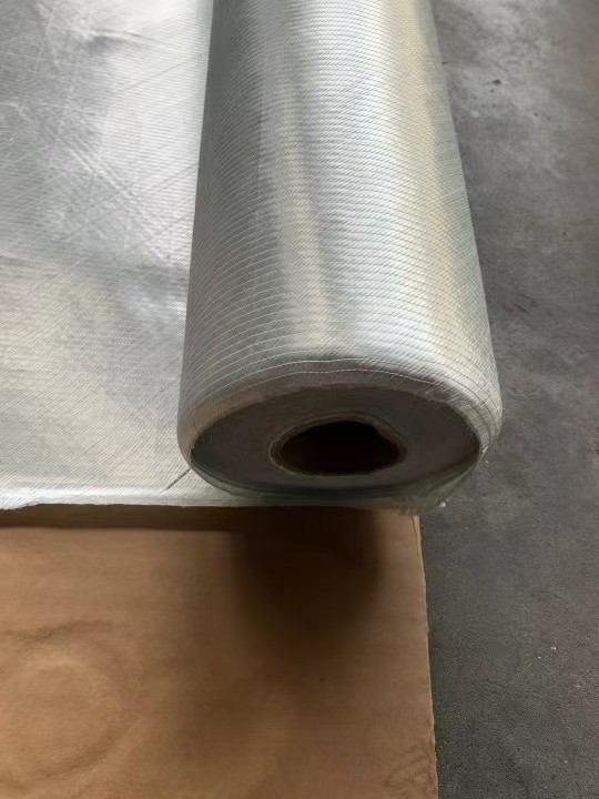
Structural composite reinforcement: multiaxial fiberglass fabric engineered for high structural strength, reduced fiber crimp and vacuum infusion compatibility.
1. Surface and skin layers: Light Weight Fiberglass Cloth
The tool face is where surface quality is won or lost. CINON's Light Weight Fiberglass Cloth is an E-Glass Fabric (model EW), plain woven, supplied at 1,000 mm and 1,010 mm widths and in weights from 25 g/m² to 400 g/m². For mold surfaces it contributes excellent conformability, a smooth surface finish and excellent resin wet-out, and it is compatible with hand lay-up, vacuum infusion and resin infusion processes.
The selection logic is straightforward: lighter grades (toward the 25 g/m² end of the range) are used where surface quality and low weight matter, and heavier grades within the 400 g/m² limit build thickness faster with fewer lay-up steps.
2. Structural build-up: Multiaxial Fiberglass Fabrics
The stiffness of a tool body comes from the reinforcement build-up behind the skin. CINON's Structural Composite Reinforcement — Multiaxial Fiberglass Fabrics — is a non-crimp fiberglass fabric supplied in four structural designs:
- Unidirectional: fibers in 0° or 90° direction
- Biaxial: fibers in 0°/90° or +45°/−45° directions
- Triaxial: +45°/0°/−45° or +45°/90°/−45° directions
- Quadriaxial: fibers in 0°/90°/−45°/+45° directions
Areal weights run from 400 g/m² to 1,500 g/m², with combustible matter specified between 2.0% and 8.0% and moisture content below 0.2%. The material is made from alkali-free glass fiber and is specified for use in vacuum, hand layup, extrusion and RTM formed products, including ship hulls, wind turbine blades, automotive components, sports equipment and large containers.
The engineering argument for choosing multiaxial NCF over woven fabric in a tool body is a package of laminate properties rather than a single figure: high structural strength, a high strength-to-weight ratio, improved load distribution, excellent resin wet-out, vacuum infusion compatibility, reduced fiber crimp, improved mechanical performance and lightweight reinforcement. In a mold that is thermally cycled repeatedly, reduced crimp and balanced load distribution translate directly into dimensional stability.
3. Core and backing layers: CT Core Material, CM Core Mat and PVC Foam Core
Where a tool needs thickness without proportional weight, a core layer replaces solid laminate. CINON's CT Core Material is a thin flow core material made from polyester nonwoven fabric, supplied at 1.5 mm, 2 mm and 3 mm thicknesses, 1.27 m width, roll lengths of 120 m, 80 m and 50 m, dry weights of 90 g/m², 120 g/m² and 160 g/m², and a maximum process temperature of 180 °C. Its listed application range includes composite tooling alongside marine and yacht building, transportation, wind energy and sports and leisure equipment.
Where a heavier structural core layer is required, CM core mat is supplied at 1.5 mm to 6 mm thickness, 1.27 m width, dry weights from 125 g/m² to 360 g/m² and a maximum process temperature of 175 °C. PVC foam core covers densities from 45 kg/m³ to 300 kg/m³ at thicknesses from 1 mm to 80 mm, with plain, grooved, perforated or scrim-backed surfaces, and is processed by vacuum infusion, RTM, hand lay-up, prepreg and VARTM. PET foam core adds a recyclable option across densities from 80 kg/m³ to 320 kg/m³.
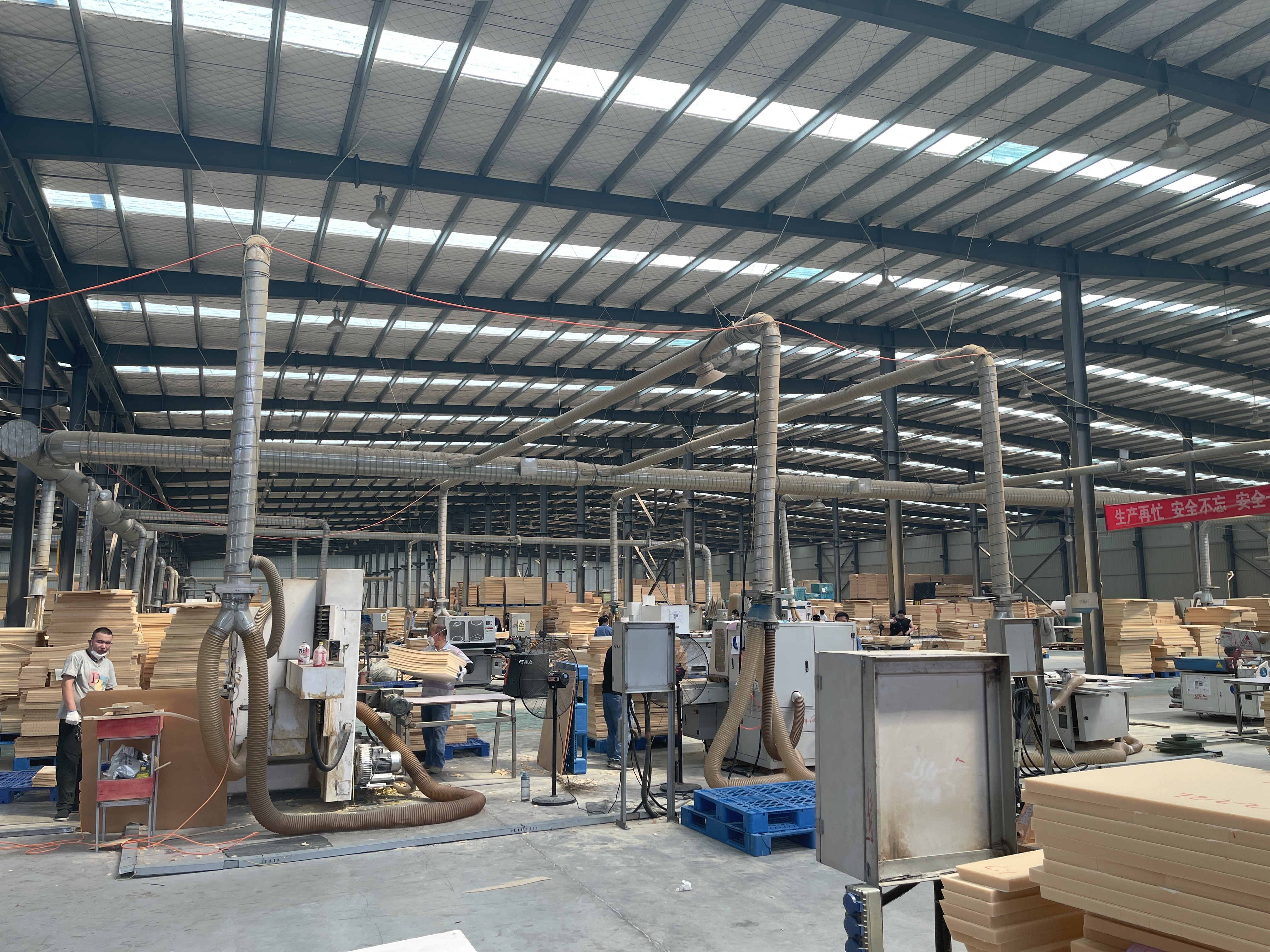
Closed-cell foam core production: the backing layer that lets a tool gain thickness without adding proportional weight.
4. Tooling route and supporting equipment
Reinforcement choice cannot be separated from the way the tool is made. Composite tooling is produced through two routes: CNC machining (direct tooling), where the tool shape is cut from a machined medium, and composite-on-composite tooling, where a composite tool is laminated over an existing master or pattern. Composite-on-composite tooling is the route where fabric format matters most, because the laminate must conform to the pattern without bridging and must cure to the intended geometry.
The matched equipment for these applications is vacuum infusion equipment and an RTM injection machine. This is consistent with a general product requirement that is worth stating plainly for anyone new to the process: this product requires supporting equipment such as vacuum bagging systems. Fiberglass reinforcement for RTM and VARTM is not a stand-alone purchase — it is one component in a process chain that includes vacuum pumps, bagging film, sealant tape, resin mixing equipment and, in RTM, an injection machine.
Step-by-Step: Specifying Fiberglass Fabric for an RTM or VARTM Mold Build
The following sequence mirrors how a tooling laminate is normally specified. Each step produces a decision that constrains the next one, which is why changing fabric format late in a project usually means re-validating the whole stack.
- Define the tool's service conditions. Establish the maximum process temperature, the injection or clamping pressure, whether the tool will see vacuum integrity requirements, and how many thermal cycles it must survive. Composite tooling applications are characterized by all four conditions: high temperature, high pressure, vacuum integrity and thermal cycling.
- Separate the surface requirement from the structural requirement. Specify a surface fabric for the tool face and a structural reinforcement for the body. For the face, a plain woven E-glass fabric between 25 g/m² and 400 g/m² gives conformability and smooth surface finish; for the body, move to multiaxial non-crimp fabric.
- Choose the fiber architecture. Unidirectional reinforcement for a dominant load direction; biaxial (0°/90° or +45°/−45°) for general tool bodies; triaxial or quadriaxial where the tool sees multi-directional loads and where thermal distortion must be minimized.
- Set the areal weight. Multiaxial fabric is available from 400 g/m² to 1,500 g/m². Heavier formats reduce the number of lay-up steps for a given laminate thickness; lighter formats give finer control over the stack and better drape over curvature.
- Verify the reinforcement specification. Confirm moisture content below 0.2% for multiaxial fabric, and check the combustible matter figure against the 2.0%–8.0% range for the grade in question. Both values affect wet-out, void content and final laminate quality.
- Decide whether a core layer is needed. If the tool must gain thickness without proportional weight, select a thin flow core such as CT Core Material (1.5–3 mm, up to 180 °C process temperature) or a heavier structural core such as CM core mat (1.5–6 mm, up to 175 °C). For foam-backed stacks, PVC foam core is specified for vacuum infusion, RTM, hand lay-up, prepreg and VARTM, at densities from 45 kg/m³ to 300 kg/m³.
- Confirm process compatibility end to end. Multiaxial fabric is specified for vacuum, hand layup, extrusion and RTM. If the tool will be built by infusion, the whole stack — surface fabric, structural fabric, core, flow media — must be compatible with the vacuum bagging system. This product requires supporting equipment such as vacuum bagging systems.
- Plan the validation test. Agree in advance which properties will be measured. Standardized tests for fiberglass reinforced materials include ASTM D638 for tensile properties and ASTM D790 for flexural strength and modulus; flexural data is the more relevant indicator for a tool laminate that bends under injection pressure.
- Lock the supply parameters. Confirm the format, weight, roll width and quantity against the supplier's minimum order quantity, production capacity and lead time before the tooling build is scheduled.
Use Cases: Where RTM and VARTM Mold Laminates Are Applied
Mold reinforcement selection is driven by the part being produced. Four application areas dominate the use of RTM and VARTM tooling, and each one prioritizes different material properties.
Aerospace and UAV structures
UAV wings, drone structures and aircraft panels are produced by RTM and VARTM. In these applications the operating conditions include high altitudes, high G-forces, vibration and fatigue. The special requirements are weight criticality, surface aerodynamics, traceability and stiffness-to-weight ratio. A mold that lacks dimensional stability cannot deliver aerodynamic surface accuracy, and a tool that is too heavy is difficult to handle in a high-cycle molding cell. Matched equipment in this segment is vacuum bagging systems. Aramid honeycomb core (working temperature −60 °C to 180 °C, densities 32–128 kg/m³) and PMI foam core (40–130 kg/m³) are used in the sandwich structures that such tools produce.
Marine and yacht building
Boat hulls, decks, bulkheads, superstructures and marine panels are produced by vacuum infusion, resin infusion, hand lay-up and RTM. The working environment is salt water, high humidity, dynamic loading and continuous corrosion exposure. Here the tool's job is to deliver weight reduction, improved stiffness and reduced resin consumption in the finished part, which depends on the mold holding vacuum and geometry over long production runs.
Wind energy
Wind turbine blades, blade shells and nacelle structures are produced by vacuum infusion, resin infusion, hand lay-up and RTM, under conditions of high and low temperature, high pressure, long-term static and dynamic load, and 24/7 continuous operation. The requirements are fatigue resistance, weight reduction, structural performance and long service life. This is the fastest-growing application segment for fiberglass fabric, projected at a CAGR of 8.5% from 2025 to 2033, and the segment where mold durability has the highest commercial consequence.
Transportation and industrial composites
Truck bodies, bus panels and rail interiors are produced under dynamic road loads, extreme thermal gradients, internal impact and frequent cycling, with weight reduction and thermal efficiency as the priorities. Industrial composite applications — industrial covers, FRP panels and machine enclosures — operate in corrosive environments and extreme outdoor weather, requiring corrosion resistance, weight reduction and structural performance. In both cases, mold and tooling laminates must hold flatness and thickness uniformity across repeated production cycles.
Comparison Table: Reinforcement and Core Options for RTM Mold Construction
The table below compares the material options described above using their published specifications. No performance ranking is implied; each row describes a different job within a tool laminate.
| Material option | Published format and key specifications | Role in an RTM / VARTM tool | Process compatibility |
|---|---|---|---|
| Light Weight Fiberglass Cloth (E-Glass Fabric, model EW) | Plain woven E-fiberglass; width 1,000 mm / 1,010 mm; 25–400 g/m² | Tool face and skin layer; surface finish, conformability, resin wet-out | Hand lay-up, vacuum infusion, resin infusion |
| Multiaxial Fiberglass Fabrics — unidirectional | Non-crimp; 0° or 90° fiber direction; 400–1,500 g/m² | Directional stiffness where one load path dominates | Vacuum, hand layup, extrusion, RTM |
| Multiaxial Fiberglass Fabrics — biaxial | Non-crimp; 0°/90° or +45°/−45°; 400–1,500 g/m² | General tool body build-up; balanced in-plane stiffness | Vacuum, hand layup, extrusion, RTM |
| Multiaxial Fiberglass Fabrics — triaxial / quadriaxial | Non-crimp; triaxial +45°/0°/−45° or +45°/90°/−45°; quadriaxial 0°/90°/−45°/+45°; 400–1,500 g/m²; combustible matter 2.0%–8.0%; moisture below 0.2% | Multi-directional load distribution; reduced crimp for dimensional stability under thermal cycling | Vacuum, hand layup, extrusion, RTM |
| CT Core Material | Polyester nonwoven thin flow core; 1.5 / 2 / 3 mm; width 1.27 m; roll length 120 / 80 / 50 m; dry weight 90 / 120 / 160 g/m²; max. process temperature 180 °C | Thin flow core / backing layer in composite tooling | Listed for composite tooling, marine, transportation, wind energy |
| CM core mat | Polyester nonwoven; 1.5–6 mm; width 1.27 m; dry weight 125–360 g/m²; max. process temperature 175 °C | Structural core layer for thickness without proportional weight | Vacuum infusion and sandwich construction |
| PVC foam core | Density 45–300 kg/m³; thickness 1–80 mm; plain / grooved / perforated / scrim-backed surfaces | Foam-backed tool and panel sandwich stacks | Vacuum infusion, RTM, hand lay-up, prepreg, VARTM |
All specifications above are as published by the supplier. Where a project requires values outside these ranges, the specification should be confirmed with the supplier before the tooling build is scheduled.
FAQ: Fiberglass Fabric for RTM Molds
Which test standards apply to fiberglass reinforcement used in RTM tooling?
Standardized tests for fiberglass reinforced materials include ASTM D638 for tensile properties and ASTM D790 for flexural strength and modulus. For a mold laminate, ASTM D790 is usually the more informative of the two, because a tool bends under injection pressure and thermal load rather than being pulled in tension. Alongside laboratory testing, reinforcement specifications themselves carry verifiable parameters — for multiaxial fiberglass fabric these include a moisture content below 0.2% and combustible matter between 2.0% and 8.0%. Suppliers that apply 100% testing to production output and can provide quality traceability documentation make compliance review easier for the buyer.
What fabric formats and weights are available for an RTM or VARTM mold build?
CINON Composites supplies two reinforcement families relevant to tooling. Light Weight Fiberglass Cloth is a plain woven E-Glass Fabric (model EW) at 1,000 mm and 1,010 mm widths and 25–400 g/m², intended for surfaces and skins. Structural Composite Reinforcement — Multiaxial Fiberglass Fabrics — is a non-crimp fabric made from alkali-free glass fiber, available as unidirectional (0° or 90°), biaxial (0°/90° or +45°/−45°), triaxial (+45°/0°/−45° or +45°/90°/−45°) and quadriaxial (0°/90°/−45°/+45°), at 400–1,500 g/m². These formats are specified for vacuum, hand layup, extrusion and RTM formed products. Core layers complete the stack: CT Core Material at 1.5–3 mm with a maximum process temperature of 180 °C, CM core mat at 1.5–6 mm with a maximum process temperature of 175 °C, and PVC foam core from 45 to 300 kg/m³ at 1–80 mm thickness.
What drives the cost of fiberglass fabric for an RTM or VARTM mold?
Cost is driven by the specification rather than by a single headline price, and the main variables are architectural. Areal weight is one: the woven surface fabric band runs from 25 g/m² to 400 g/m², while multiaxial structural fabric runs from 400 g/m² to 1,500 g/m². Architecture is another: a quadriaxial stitched fabric with fibers in four directions costs more to produce than a unidirectional fabric, but it may replace several separate layers in the tool laminate and reduce lay-up labour. Core selection is a third variable — thin flow core, core mat and foam core sit at different positions in the stack and are priced accordingly. Finally, order quantity interacts with the supplier's minimum order quantity and production capacity. For CINON Composites, the minimum order quantity is 1,000 m² and monthly capacity is 100,000 m², so tool builders should plan reinforcement volumes against the tooling schedule rather than ordering per tool.
Can a sample be evaluated before committing to a tooling project?
Yes. Sample evaluation is part of the after-sales support offered by CINON Composites, alongside material selection, composite process optimization, vacuum infusion guidance, alternative material recommendations, quality traceability and global logistics coordination. Support is delivered through email, WhatsApp, online meetings and technical documentation, and is intended to cover the path from prototype development to mass production. For tooling projects, a practical evaluation looks at resin wet-out, drape over the pattern, cured laminate quality and surface finish before the full tool laminate is committed.
What is the lead time for fiberglass fabric on a tooling programme?
CINON Composites quotes a lead time of 15–30 days, with a monthly production capacity of 100,000 m² and an annual output of 1,200,000 m² from a 40,000 m² facility, exporting to Europe, North America and Asia-Pacific. Tooling programmes usually consume reinforcement across several builds, so the useful planning question is not only the lead time for one order but whether the supplier can hold the same specification across repeat orders. To move forward, request a sample or a quotation for your RTM or VARTM mold specification by contacting waylon@cinoncomposites.com, calling +86 186-2098-8848, or messaging on WhatsApp at +86 135-8036-3674. The full product range is documented in the CINON catalogue.
Conclusion: Specifying the Tool, Not Just the Part
High-stiffness composites start with the mold that shapes them. For RTM and VARTM tooling, that means treating fiberglass fabric as an engineered part of the tool design: a woven E-glass surface fabric for conformability and finish, a multiaxial non-crimp structural laminate for stiffness and load distribution, and a core layer where thickness must be gained without proportional weight. The dimensions that decide whether the tool survives thermal cycling are the ones that appear in the reinforcement specification sheet — fiber architecture, areal weight, moisture content and process compatibility.
The materials described in this guide are supplied by CINON Composites, which manufactures fiberglass reinforcements and lightweight core materials for marine, transportation, wind energy, industrial and aerospace composite applications, with ODM capability for core materials and fiberglass fabric.
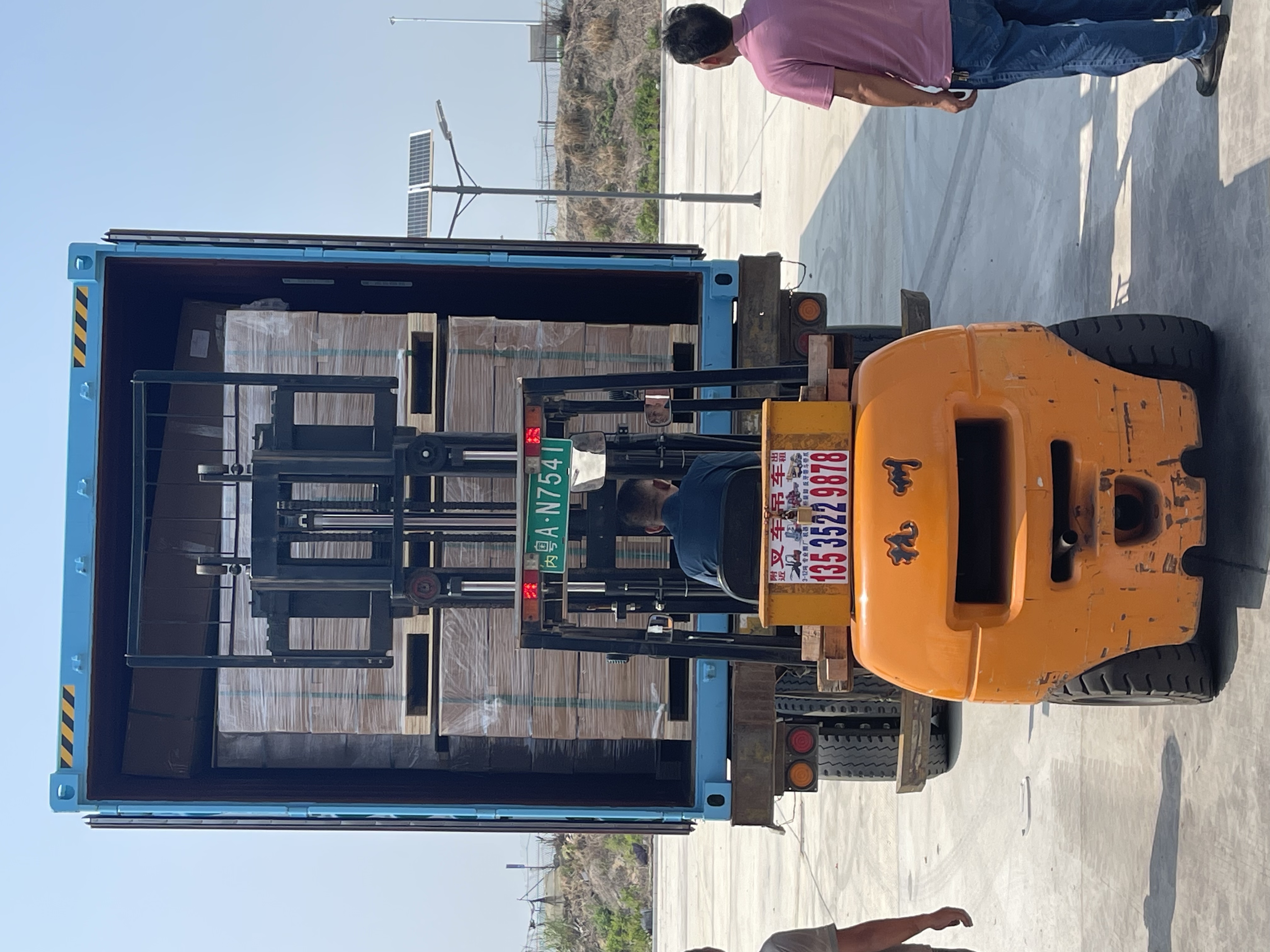
Next step for tooling engineers: send your RTM or VARTM mold specification — tool size, process temperature, target laminate thickness and fiber architecture — and request a sample or a quotation.
Email: waylon@cinoncomposites.com | Tel: +86 186-2098-8848 | WhatsApp: +86 135-8036-3674
Website: cinoncomposites.com | Blog: blog.cinoncomposites.com
Download the full product range: CINON Composites Catalogue (PDF)
Have Questions or Need More Details?
Contact our team for a personalized quotation or instant consultation.
Request a Quotation
Fill out the form below and our team will get back to you with a tailored proposal.
WhatsApp Direct Chat
Prefer to chat in real-time? Message us on WhatsApp for instant assistance & quick answers.
- Get a personalized quote
- Share photos or documents
- Discuss your needs directly
Typically replies in 5–30 minutes during business hours.