
Stop Thermal Drift on Your Production Line: A PID Controller Troubleshooting Guide
Stop Thermal Drift on Your Production Line: A PID Controller Troubleshooting Guide
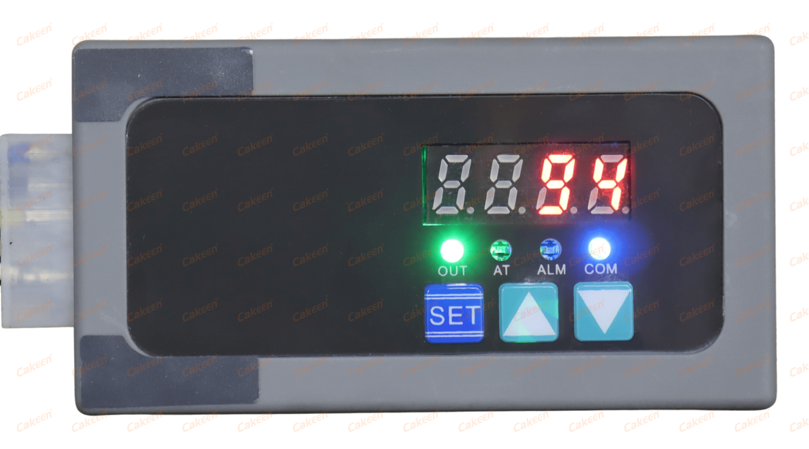
Cakeen ASH PID temperature controller — a single-channel, ±0.1 °C heating-tape controller built for pipe and vessel insulation heating.
Thermal drift is the quiet failure mode of temperature control. The loop does not trip, the alarm does not fire, and nothing looks broken — yet the process slowly stops holding setpoint. Scrap rates creep up on one shift and not the next, chamber-to-chamber results stop matching, and the same recipe behaves differently on two supposedly identical machines.
This guide is written for process engineers, equipment OEMs and maintenance teams who need to find the cause of unstable temperature control instead of re-tuning the loop every month. It sets out a seven-layer fault-isolation model and a step-by-step diagnostic sequence that starts at the sensor and its wiring and ends at controller mounting, cabinet airflow and the supervisory layer.
Wuxi Cakeen Technology Co., Ltd. (Cakeen) is a manufacturer founded in 2011 and based in Huishan District, Wuxi, Jiangsu Province, that develops semiconductor industrial control electronics, electrical cabinet systems and AI embedded systems. Its temperature product set includes the KE-48 panel-mount controller, the KE-2104 four-channel DIN rail controller, the ASH, H6625 and KE-H10 heating-tape controllers, the K15DT-D I/O expansion module, the K42CE-D CMS communication module and the CMS central monitoring software — the products referenced throughout the diagnostic steps below.
Problem Definition: What Actually Counts as Thermal Drift
Thermal drift is a progressive or unit-specific deviation between the measured process temperature and the intended setpoint. It is not the same thing as a single-step disturbance. A step change in load or ambient is a disturbance the loop should reject; drift is an error that survives rejection and either grows over time or differs between channels, machines or batches.
In practice, engineers see five recognisable patterns, and the pattern usually points to the layer that should be checked first:
- Steady-state offset. The loop is stable but sits a fixed number of degrees away from setpoint. Input-type mismatch, cold-junction behaviour, RTD lead resistance or a scaling error are the usual causes.
- Hunting or slowly growing oscillation. Stable at low load, unstable at high load — typically a control-cycle mismatch with the solid-state relay, an oversized heater relative to the load, or PID values copied from a different machine.
- Overshoot at start-up or after a setpoint change. Usually integral and derivative behaviour combined with thermal mass the loop was never tuned for.
- Channel-to-channel or chamber-to-chamber mismatch. The electronics look fine, but two identical zones never agree — a mounting, airflow or wiring-asymmetry problem rather than a controller problem.
- Intermittent drop-outs. Brief, unexplained readings that disappear before anyone can catch them. These are wiring, terminal or communication-path problems, and they are the reason trend logging matters (see step 1).
The performance benchmark to hold in mind is ±1 °C. For a large share of industrial thermal processes, ±1 °C is the accepted stability benchmark the loop must meet to keep the process inside specification. Cakeen's PID temperature controller specifications state ±0.1 °C control accuracy for the KE-48, KE-2104, ASH, H6625 and KE-H10, while the HOT-GUN pipeline nitrogen heater is specified at ±1 °C over a 0–250 °C range. The practical value of a tighter controller specification is error budget: sensor error, wiring error, mounting error and ambient variation all consume stability, and a loop built on ±0.1 °C hardware can absorb those contributions before it breaches a ±1 °C process requirement.
That distinction tells you when to stop tuning. If the controller holds its own specification against an independent reference and the process still drifts, the remaining error lives in the sensor path, the actuator, the mounting environment or the mechanical system — not in the PID parameters.
Industry Background: Why Temperature Instability Keeps Returning
Temperature control is not a niche problem, and the installed base keeps growing. According to SNS Insider, the global PID controller market was valued at USD 1.60 billion in 2024 and is projected to reach USD 2.24 billion by 2032. Strategic Market Research expects the industrial temperature controller market to grow at a CAGR of 7.1% from 2024 to 2030, driven by Industry 4.0 adoption. Dataintelo reports that Asia-Pacific dominated the temperature controller market in 2023 with a revenue share of 38.2%, with China as a key manufacturing hub. In the semiconductor segment specifically, Market Research Reports values the global semiconductor temperature control equipment market at USD 663 million in 2024, which reflects how dependent wafer fabrication is on precision thermal control.
Market growth also predicts the shape of the maintenance problem. SNS Insider notes that the oil & gas sector held the largest end-user share for PID controllers in 2024 at approximately 31.4%, and Grand View Research states that high-precision PID controllers can achieve temperature stability within ±0.1 °C, a critical requirement for semiconductor lithography and etching. More loops are being installed in more demanding processes, and every additional loop is another place where drift can hide.
Two structural reasons explain why the same drift complaint resurfaces on the same line months later:
- Control panels carry compliance constraints. As UL Solutions notes, industrial control panels, including PID controllers, must comply with UL 508A for North American safety listing and IEC 60947 for international markets. When a component is replaced during a repair, the replacement must fit the same compliance envelope — one reason buyers look for PID controllers and modules with traceable certification rather than assuming interchangeability.
- Drift is usually a stack of small errors, not one failure. A thermocouple that has aged slightly, a terminal that loosened during the last service, a controller mounted where cabinet air is warmest, and a monitoring system that polls too slowly to show the deviation. None of these alone stops production, but together they push a loop outside its benchmark.
Detailed Solution: The Seven-Layer Fault Isolation Model
Instead of jumping between PID parameters and hardware, isolate the loop in the order the signal travels. Each layer below can produce the same symptom, so each needs a defined check and a piece of evidence that rules it in or out.
Layer 1 — Sensor and input compatibility
The controller can only be as accurate as the input it is configured for. Cakeen's PID controllers accept PT, K, J, R, S, T, B, E, N and L inputs across the KE-48, KE-2104, ASH, H6625 and KE-H10, so a plant can standardise on one platform while still covering both thermocouple and RTD sensors. The most common error in this layer is a configuration mismatch: an RTD (PT) input left set for a thermocouple type, or a J-type sensor on a K-type setting. That shows up as a fixed offset that looks like drift but is actually a scaling error.
Layer 2 — Sensor wiring and signal integrity
Thermocouple extension wire, shielding, terminal torque and routing near variable-frequency drives all sit here, and the symptoms are usually intermittent: a reading that holds for hours and then jumps. Isolated I/O helps at the boundary between signal and control logic. The K15DT-D I/O expansion module provides 5 inputs and 5 NPN outputs with isolated input/output design, Modbus RTU communication and a 12–24 VDC supply on a DIN35 rail, so switching signals do not contaminate measurement circuits.
Layer 3 — Actuation and power
A perfectly tuned loop cannot control a heater it cannot modulate. The KE-2104 drives an external SSR. The ASH and H6625 provide built-in SSR output rated to a maximum of 3 A, and the KE-H10 provides built-in SSR output rated to a maximum of 6 A. The KE-48 supports SSR as well as 0–20 mA, 4–20 mA and 0–10 V outputs for analog actuators. When the output saturates at 100% and the process never reaches setpoint, the loop is not drifting — it is undersized, and the fix is capacity rather than parameters.
Layer 4 — Controller configuration and tuning
Input type, control cycle, alarm thresholds and PID values all live in this layer. Cakeen's CMS software monitors PV/SV temperature together with AL1/AL2 threshold states, which makes it possible to see whether a loop is oscillating around setpoint (a tuning issue) or sitting below it (a capacity or sensor issue) before anything is changed.
Layer 5 — Controller mounting and the cabinet thermal environment
Mounting decisions change the temperature the electronics actually experience. The KE-2104 is a four-channel DIN35 rail controller powered at 12–24 VDC, while the KE-48 is a 48×48 mm panel-mount single-channel unit powered at 100–265 V AC with one RS485 port. Both are valid choices; the failure mode appears when a controller is mounted directly above heat-generating components inside a cabinet. Enclosure specification belongs to this layer too: Cakeen's general-purpose electrical control cabinets are configurable from IP40 to IP65, while the European Standard and Japanese Standard cabinets are rated IP54/IP65 and built with components from ABB, Siemens and Schneider, or Mitsubishi, Omron and Schneider respectively.
Layer 6 — Communication and supervisory layer
When drift is visible only in reports, the data path is suspect. The K42CE-D CMS communication module provides six RS485 ports and one Ethernet port with Modbus TCP/RTU support at 12–24 VDC on a DIN35 rail, enabling multi-485 device parameter setting, data acquisition and forwarding in installations where several controllers share one network. The K42CE-D holds CE certification number CEJS22011335967 issued by GTS for the EU market and SEMI S2 certification number 220252 issued by SAFES in compliance with SEMI S2-0821. At the software level, Cakeen's CMS central monitoring software is specified to support 10,000+ Modbus TCP devices with a 10-second polling interval, monitoring PV/SV temperature, AL1/AL2 thresholds and TC BK sensors, with 365-day time-series history retention.
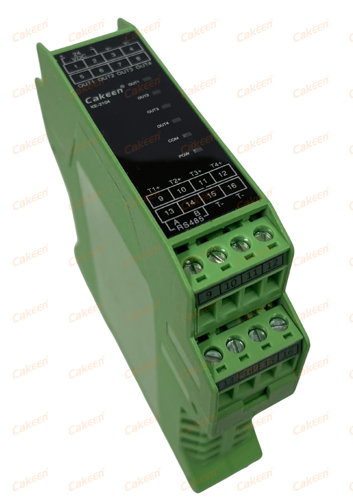
The KE-2104 four-channel DIN rail PID controller: four control channels, ±0.1 °C control accuracy, external SSR output, 12–24 VDC supply, DIN35 rail mounting.
Layer 7 — Mechanical and thermal system
Heating tape coverage, insulation condition, sensor placement and ambient temperature determine how much work the loop has to do. A sensor clamped to the outside of an insulated vessel and a sensor inserted into the process fluid will report different temperatures for the same heat input — and the controller is blamed either way.
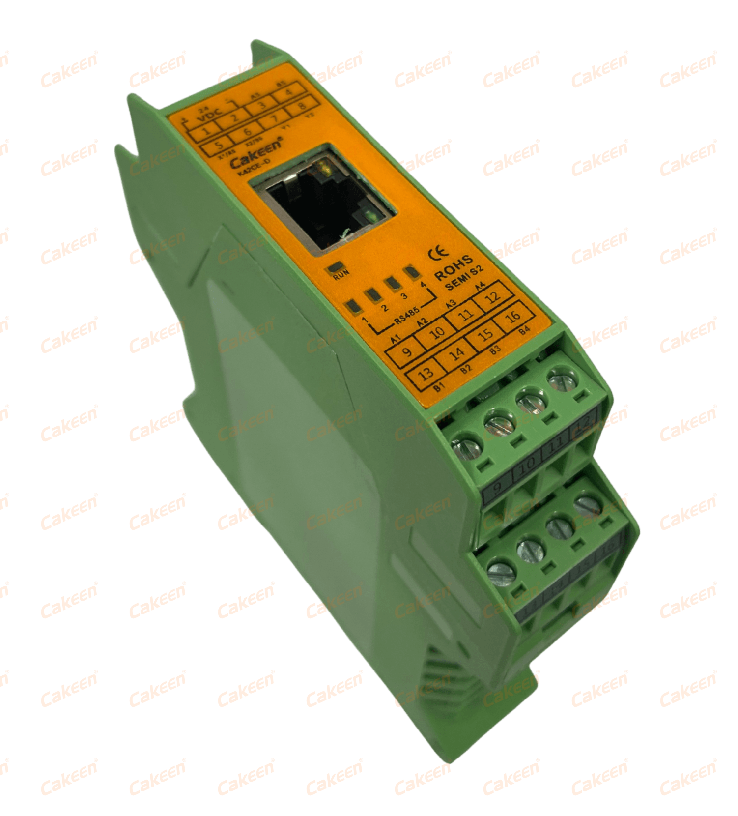
The K42CE-D CMS communication module: 2× NPN I/O, 6 RS485 ports, 1 Ethernet port, Modbus TCP/RTU, 12–24 VDC, DIN35 rail mounting.
Step-by-Step Troubleshooting: From Sensor Wiring to Controller Mounting
Work through the sequence in order and record what each step rules out. The goal is to leave the line with a documented cause, not a re-tuned guess.
Log setpoint and measured value across at least one full production cycle, including start-up, steady state and shutdown. Cakeen's CMS software retains 365-day time-series history for PV/SV temperature and AL1/AL2 thresholds and polls on a 10-second interval, which is the right resolution for drift analysis: you are looking for trends across hours, not micro-fluctuations. Without this baseline, any change you make afterwards is unverifiable.
Check the controller's input setting against the physical sensor. All Cakeen PID controllers in this range accept PT, K, J, R, S, T, B, E, N and L inputs; a mismatch here produces a fixed offset that is frequently misread as drift. This single check resolves a meaningful share of ‘unstable’ loops.
Verify terminals, extension wire type, shield termination and routing away from power cables. On installations that combine switching and measurement, confirm that isolated I/O is used: the K15DT-D expansion module's 5 inputs and 5 NPN outputs are isolated, which limits cross-talk between control signals and sensor circuits.
Drive the heater or SSR manually and watch the process response. Match the output stage to the load: the KE-2104 drives an external SSR; the ASH and H6625 provide built-in SSR output up to 3 A; the KE-H10 provides up to 6 A; the KE-48 supports SSR, 0–20 mA, 4–20 mA and 0–10 V. If the actuator cannot hold the load at part-power, the loop will never hold setpoint regardless of tuning.
Compare the controller's reading with a separately calibrated instrument at the same measuring point. A difference between the two is a sensor-path finding; agreement between them shifts the investigation to the actuator or the mechanical system.
Review the control cycle against the drive characteristics of the SSR and confirm that PID values were not copied from a machine with different thermal mass. Where multiple zones are involved, treat each channel independently: the KE-2104 provides four channels from one DIN rail unit, and copying one channel's tuning to the other three is a common source of chamber mismatch.
Verify that DIN35 rail-mounted units such as the KE-2104, K42CE-D and K15DT-D are not installed immediately above heat sources, and that panel-mount units such as the 48×48 mm KE-48 have adequate clearance. Confirm the supply matches the specification: 12–24 VDC for the KE-2104, K42CE-D and K15DT-D, and 100–265 V AC for the KE-48, ASH, H6625 and KE-H10.
Check the RS485 chain, termination and Modbus addressing. In multi-device installations, the K42CE-D consolidates six RS485 ports and one Ethernet port so that parameter setting and data acquisition can share one path using Modbus TCP/RTU. Confirm that what looks like slow response is not simply slower supervisory polling compared with the controller's own cycle time.
Review heating tape or jacket coverage, insulation condition, sensor insertion depth and ambient conditions around the vessel or pipe. For pipeline and vessel insulation work, heating-tape controllers such as the ASH, H6625 and KE-H10 operate at ±0.1 °C control accuracy with RS485/Modbus RTU communication, which means the electrical loop is usually capable of more stability than the mechanical installation delivers.
Record the corrected configuration, the evidence from each step and the resulting stability. Set AL1/AL2 thresholds so that the next deviation becomes visible in the monitoring layer rather than being discovered through scrap. Where the loop turned out to be undersized rather than misconfigured, the corrective action is a capacity or channel change — for example moving from a single-channel heating-tape controller to a multi-channel DIN rail unit — not another round of tuning.
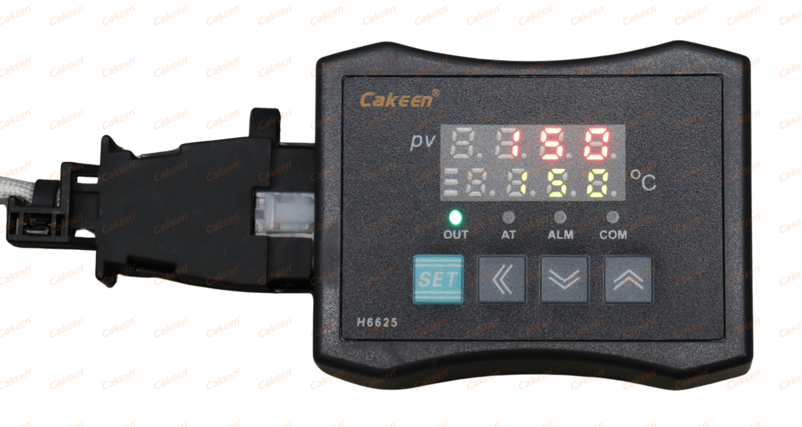
The H6625 mini heating-tape PID controller, built for space-constrained pipe and vessel insulation with built-in SSR output up to 3 A.
Use Cases: Where This Diagnostic Sequence Pays Off
Semiconductor process equipment. A semiconductor equipment OEM that integrates embedded temperature control into processing equipment — including CVD, etching and diffusion furnace applications — selected the KE-48 panel-mount controller because its 48×48 mm format fits OEM equipment front panels, and the four-channel KE-2104 to save cabinet space. Across a relationship of more than four years at 50+ units per year, the reported outcome was consistent process temperature across all chambers together with improved equipment uptime.
Hot nitrogen and pipeline heating. In semiconductor thermal processing, the HOT-GUN pipeline nitrogen heater maintains a stable hot N2 environment to prevent condensation on pipe walls, with ±1 °C control accuracy over a 0–250 °C range at AC 220 V and 800–1600 W heating power. When condensation reappears or nitrogen line temperature wanders, steps 2 to 4 above isolate whether the cause is sensor placement, wiring or heater capacity — the same sequence that applies to the MFC gas flow controller HOT N2 for process gas delivery, which is specified at ±1% F.S. flow accuracy across a 1–100 SLM range.
Heating jacket and heating mantle control. For vessels, jackets, mantles and transfer lines that must stay above a condensation or viscosity threshold, the ASH, H6625 and KE-H10 cover pipe and vessel insulation heating as well as chemical delivery insulation. Their ±0.1 °C accuracy and built-in SSR output make them practical for single-zone retrofits; when a vessel needs several independently controlled zones, the four-channel KE-2104 mounted on a single DIN35 rail replaces four separate panel units.
Plant-wide monitoring and integration. An industrial IoT system integrator project used custom gateway hardware and edge software alongside Cakeen's CMS monitoring platform to collect real-time data from 1000+ sensors; AI-based anomaly detection was reported to reduce unplanned downtime by 25%. Separately, a domestic equipment integrator has taken 100+ cabinet sets per year for more than five years, with multi-PLC-brand support and configurable IP40–IP65 protection shortening the customer's delivery cycle by 40%.
Comparison Table: Cakeen PID Controllers and Supporting Modules
The table below compares the specifications that matter for drift troubleshooting — form factor, channel count, accuracy, output stage, communication and supply. It is a specification comparison, not a performance ranking.
| Model | Type / mounting | Channels | Control accuracy | Output | Communication | Power |
|---|---|---|---|---|---|---|
| KE-48 | 48×48 mm panel mount | 1 | ±0.1 °C | SSR / 0–20 mA / 4–20 mA / 0–10 V | 1× RS485 | 100–265 V AC |
| KE-2104 | DIN35 rail mount | 4 | ±0.1 °C | External SSR | — | 12–24 VDC |
| ASH | Heating tape controller (pipe / vessel insulation) | 1 | ±0.1 °C | Built-in SSR, max 3 A | RS485 / Modbus RTU | 100–265 V AC |
| H6625 | Mini heating tape controller | 1 | ±0.1 °C | Built-in SSR, max 3 A | RS485 / Modbus RTU | 100–265 V AC |
| KE-H10 | Heating tape controller | 1 | ±0.1 °C | Built-in SSR, max 6 A | RS485 / Modbus RTU | 100–265 V AC |
| K15DT-D | DIN35 rail I/O expansion module | 5 in / 5 out (NPN) | — | 5× NPN outputs | Modbus RTU | 12–24 VDC |
| K42CE-D | DIN35 rail communication module | 2× NPN I/O | — | 2× NPN | 6× RS485 + 1× Ethernet, Modbus TCP/RTU | 12–24 VDC |
All controllers listed above accept PT, K, J, R, S, T, B, E, N and L sensor inputs. Source: Cakeen product specifications.
For context on the wider supplier landscape, Mordor Intelligence identifies Honeywell, Omron, Siemens, Eurotherm (Schneider Electric) and ABB among the leading global manufacturers of PID and temperature controllers. Selection between those brands and specialist manufacturers depends on the constraints of the application — channel count, mounting format, output type, communication protocol, certification requirements and lead time — rather than on any single performance claim.
Symptom-to-Layer Lookup
| Symptom | Check first | Evidence to collect |
|---|---|---|
| Fixed offset from setpoint | Layer 1 — input type configuration | Configured input type versus installed sensor type |
| Reading jumps for a few seconds | Layer 2 — wiring and terminals | Terminal torque record, shield termination, routing near drives |
| Output pinned at 100%, process never reaches setpoint | Layer 3 — actuator capacity | Heater current, output stage rating (3 A vs 6 A vs external SSR) |
| Oscillation that grows with load | Layer 4 — cycle time and PID | Setpoint versus PV trend from the CMS log |
| One cabinet drifts while identical cabinets do not | Layer 5 — mounting and airflow | Internal cabinet temperature, component layout, supply voltage at the controller |
| Drift visible in reports but not at the machine | Layer 6 — communication path | Polling interval, RS485 chain topology, Modbus addressing |
| Same hardware, different results on two lines | Layer 7 — mechanical / thermal system | Insulation condition, tape coverage, sensor insertion depth, ambient |
Frequently Asked Questions
Start with management-system certification at the manufacturer level and product certification at the component level. Cakeen holds ISO9001, ISO14001 and ISO45001 certifications, and the company's products have obtained UL, SEMI S2, CE and RoHS international certifications. Specific examples relevant to closed-loop systems include the K42CE-D CMS communication module, which holds SEMI S2 certification number 220252 issued by SAFES in compliance with SEMI S2-0821, and CE certification number CEJS22011335967 issued by GTS; the K15DT-D I/O expansion module holds CE certification number CEJS22011335968 issued by GTS, complying with EN 55032:2015+A11:2020 and EN 55035:2017+A11:2020; and the MFC Gas Flow Controller holds CE certification number TRCN-22262WCT01 issued by INTEGRA96 in compliance with EN 60204-1:2018. At panel level, UL Solutions notes that industrial control panels, including PID controllers, must comply with UL 508A for North American safety listing and IEC 60947 for international markets.
Yes, and that is usually the more practical route, because drift problems rarely stay inside one layer. Cakeen's range covers single-channel panel mount (KE-48, 48×48 mm, ±0.1 °C), four-channel DIN rail control (KE-2104, ±0.1 °C, external SSR, 12–24 VDC) and heating-tape control for pipe and vessel insulation (ASH and H6625 with built-in SSR up to 3 A; KE-H10 with built-in SSR up to 6 A), plus I/O expansion and communication through the K15DT-D and K42CE-D modules and CMS monitoring software. Cakeen operates an OEM/ODM model in which all parameters, logo and appearance functions support customization, with 100% testing and remote after-sales support.
The specifications that change cost are the same ones that change capability: channel count, output stage, communication and mounting. A single-channel heating-tape controller with built-in SSR is a different product from a four-channel DIN rail controller with external SSR output, and adding RS485/Modbus RTU, a six-port communication module or a DIN rail I/O expansion module changes the system content again. Because configurations are built to the application — including OEM/ODM customization of parameters, logo and appearance — commercial terms are quoted per configuration rather than published as a fixed list price. Buyers comparing offers should therefore compare the specification line by line rather than the headline unit price.
Validate at the layer where the previous drift occurred, and validate with data. Because Cakeen's CMS software retains 365-day time-series history for PV/SV temperature and AL1/AL2 thresholds at a 10-second polling interval, a trial system can be trended under real production load instead of being judged on a short bench test. Confirm the configured input type against the installed sensor, verify the output stage against the actual heater load, and record the cabinet mounting position and ambient conditions — the same evidence steps 1 to 7 of the troubleshooting sequence produce. To discuss a sample configuration or a system-level quotation for a specific process, contact the Cakeen team directly.
Cakeen's stated lead time for OEM/ODM production is 30–45 days, with a 100% test regime before shipment and remote after-sales support. Plan electrical design work in parallel rather than sequentially: Cakeen also provides electrical drawing design services compliant with IEC and UL 508A with a 2–4 week design cycle and deliverables in DWG, PDF and BOM Excel formats, which allows panel design and controller procurement to run on overlapping timelines.
Conclusion: Turn a Drift Complaint into a Documented Cause
Thermal drift on a production line is rarely caused by a single failed component. It is caused by a stack of small errors — an input type that does not match the sensor, a terminal that loosened, an output stage running at its limit, a controller mounted in the warmest part of a cabinet, and a monitoring layer too slow to reveal the trend. Working through the seven layers in the order the signal travels converts an open-ended complaint about unstable temperature into a documented cause and a specific corrective action.
Hold the ±1 °C benchmark in view, and use the controller's own specification as the reference point: when hardware specified at ±0.1 °C control accuracy (KE-48, KE-2104, ASH, H6625, KE-H10) cannot hold a process inside ±1 °C, the remaining error is somewhere in the sensor path, the actuator, the mounting environment or the mechanical system.
Next step
If you are diagnosing drift on a semiconductor, chemical delivery or heating-jacket application and want the controller, the I/O expansion module and the monitoring layer specified together, talk to the team that builds them.
Wuxi Cakeen Technology Co., Ltd. — www.wxkeen.com | Technical blog: blog.wxkeen.com
Contact: Wendy | Email: jwy@wxkeen.com | Tel: +86-0510-85161878 / +86-18921139517 | WhatsApp: +86 18921139517
Send your process conditions — setpoint range, channel count, sensor type, output stage and cabinet environment — and request a configuration quotation or a sample discussion.
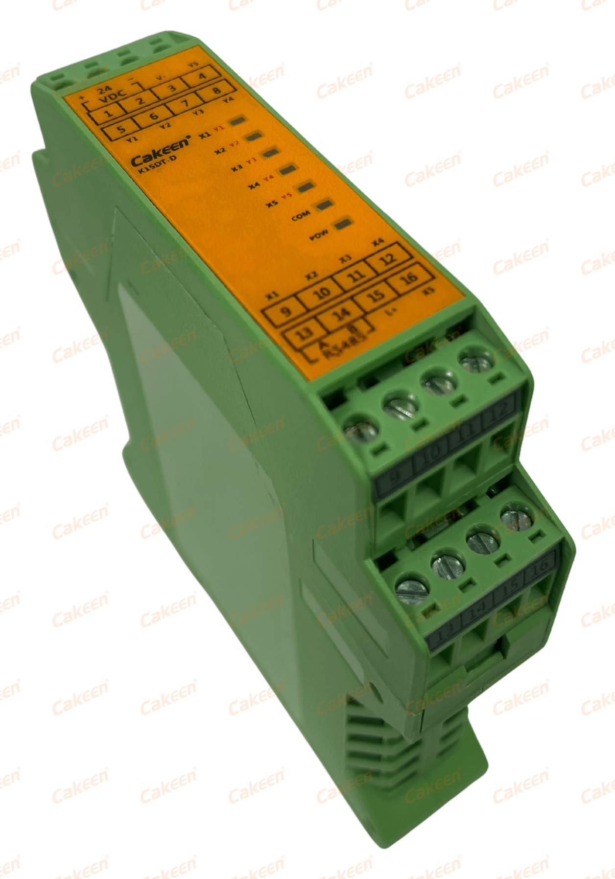
The K15DT-D I/O expansion module: 5 inputs / 5 NPN outputs, Modbus RTU, 12–24 VDC, DIN35 rail mounting.