
Electrical Switchgear Selection: Current, Voltage, Fault Level & IP
Electrical Switchgear Selection: Current, Voltage, Fault Level & IP
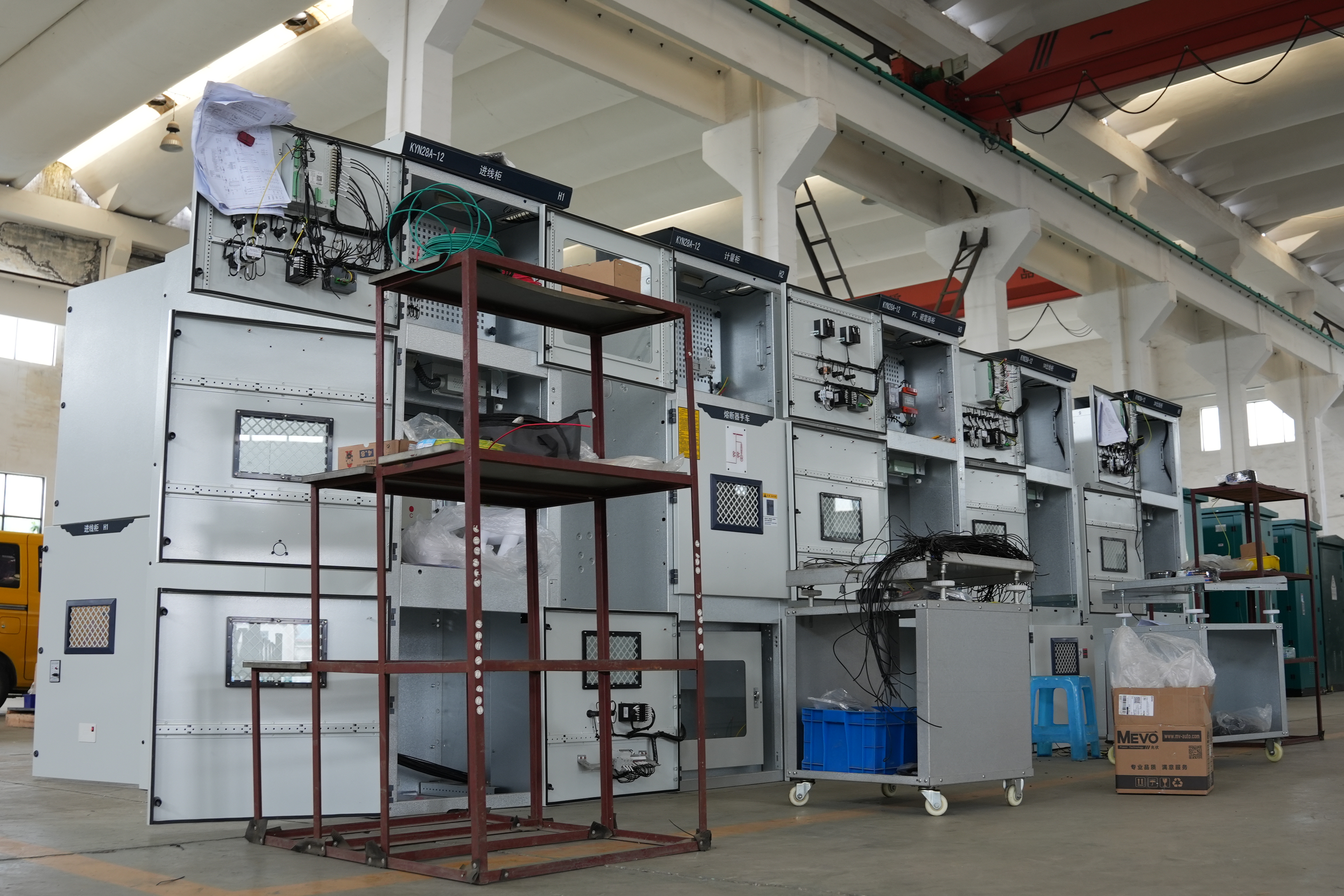
To select electrical switchgear for a distribution scheme, match five parameter groups to the project: system voltage and insulation level, continuous current, short-circuit withstand and breaking capacity, ingress protection, and construction or maintenance mode. A model family rating is only the starting range. The final choice must use the single-line diagram, prospective fault current, ambient conditions, operating voltage, and the required IP protection.
This guide is written for project engineers at the evaluation-to-execution stage. It uses supplied model data as worked examples: GCS, GCK, and MNS low voltage withdrawable switchgear with rated insulation voltage 660 V, operational voltage 380 V/660 V, and main busbar 1600–4000 A; GGD fixed switchgear at 600–1600 A; and KYN28-12 indoor metal-clad withdrawable AC switchgear at 12 kV, 630–4000 A, 50 Hz. It also shows how those ratings connect to adjacent equipment such as CMC enclosed busway, XQJ LQ cable tray, XL AC distribution boxes, and the XGN15-12 SF6 ring main unit for 3.6–12 kV networks.
The central point is simple: switchgear selection is a chain of compatible ratings. A cabinet with a 4000 A busbar is not automatically suitable for a 4000 A load, and a 12 kV rating alone does not confirm that the insulation, fault level, IP protection, and cable or busway interfaces fit the installation.
Problem definition: why one rating is not a selection
Many early equipment lists reduce switchgear to a voltage and a current. That is enough to start a supplier discussion, but not enough to place an order. A low voltage electrical switchgear assembly has to carry normal load current, withstand fault current for a specified time, interrupt fault current through its protective devices, insulate against transient overvoltages, and protect people from contact with live parts.
The same problem appears in high voltage electrical switchgear. A 12 kV indoor metal-clad withdrawable assembly may fit the nominal voltage, but the design still needs the correct rated current, short-time withstand current, short-circuit breaking capacity, lightning impulse withstand voltage, and protection degree for the room and operating procedure. If one parameter is treated as a substitute for the others, the result is either an oversized cabinet with a mismatched fault rating or a low-cost cabinet that cannot be safely integrated.
Selection errors also cross equipment boundaries. A main switchgear cabinet may be correctly rated while the enclosed busway, cable tray route, distribution box, or ring main unit is undersized or specified to a different voltage and fault assumption. For that reason, the parameter review should cover the full power path, not only the largest cabinet.
Industry background: standards define the parameter language
IEC 61439-1:2020 sets out general definitions, service conditions, construction requirements, technical characteristics, and verification requirements for low voltage switchgear and controlgear assemblies. The IEC 62271 family is associated with high voltage switchgear and controlgear; the applicable part depends on the equipment type and voltage range, and the exact edition should be confirmed for the project. These standards provide the vocabulary for the datasheet, but a standard reference is not proof that a particular assembly has been tested to it. Buyers should request the applicable standard edition, the type or design verification documents, and the product-specific ratings.
Demand context can explain why distribution capacity is being reviewed, but it does not choose the equipment. The International Energy Agency’s Electricity 2025 analysis reported that global electricity demand rose by 4.3% in 2024 and is forecast to grow at close to 4% out to 2027. For a project engineer, the useful implication is procedural: check spare capacity and future extension early, then confirm the actual fault level and load profile before fixing a switchgear rating.
| Parameter | What it tells the engineer | Selection check |
|---|---|---|
| Rated insulation voltage | The insulation design level of the assembly | Must be suitable for the system voltage and insulation coordination |
| Operational voltage | The normal service voltage of the circuit | Must match the actual network, not a higher insulation value |
| Rated current and main busbar | Continuous current capability of the assembly and busbar | Must cover diversified load with the agreed margin and derating |
| Rated short-time withstand current | Fault current the assembly can carry for a specified time | Must be at least the prospective fault level at that point |
| Short-circuit breaking capacity | Fault current the switching device can interrupt | Must coordinate with the device rating and protection settings |
| IP protection | Protection against solid objects, water, and access | Must suit the room, dust, moisture, and operating procedure |
Voltage: rated insulation, operational voltage, and impulse withstand
Voltage selection starts with the network, not the catalogue. The nominal system voltage determines the operational voltage, while the insulation level must also consider transient overvoltages and the required impulse withstand. The rated insulation voltage of low voltage switchgear can be higher than the operational voltage; that does not mean the assembly should be operated at the insulation value.
For the low voltage withdrawable families GCS, GCK, and MNS, the supplied data lists rated insulation voltage 660 V and operational voltage 380 V/660 V. This means the project engineer should confirm the actual network voltage and the insulation coordination requirement, then use the operational voltage for normal service. A 660 V insulation rating is not a substitute for a 660 V operational requirement unless the assembly configuration is actually rated and documented for that service.
For high voltage electrical switchgear, the KYN28-12 indoor metal-clad withdrawable AC switchgear is listed at 12 kV, 630–4000 A, 50 Hz. The 12 kV value identifies the voltage class; the engineer still needs the highest system voltage, lightning impulse withstand voltage, and applicable insulation requirements for the project. The 50 Hz rating must also match the network frequency. A 60 Hz system needs explicit confirmation rather than an assumption that the assembly can be applied unchanged.
Lightning impulse withstand voltage is the insulation level under a specified impulse waveform. It is relevant to high voltage switchgear and to the coordination of insulation across transformers, cables, and incoming lines. It is not a measure of continuous current and not a replacement for short-circuit withstand. When matching equipment to a distribution scheme, list the lightning impulse withstand voltage beside the rated voltage so that the insulation level is not lost in a general 12 kV description.
Current: main busbar, rated current, and load profile
Current selection has two layers: the main busbar and the individual circuit ratings. The supplied data for GCS, GCK, and MNS lists a main busbar range of 1600–4000 A. That is a family-level range. The selected configuration must still show the actual busbar rating, the incoming device rating, the outgoing circuit ratings, and the assumed ambient and installation conditions.
GGD fixed switchgear is listed at 600–1600 A. This range suits projects that do not need the draw-out maintenance model of GCS, GCK, or MNS, but the lower and upper values are not interchangeable. The engineer should calculate the diversified load, add the agreed design margin, and confirm the actual current rating with the manufacturer. The main busbar rating must be at least the total downstream load under the agreed operating assumptions; it should not be chosen only from the largest outgoing circuit.
KYN28-12 is listed at 630–4000 A for the 12 kV class. At medium voltage, the rated current should be read with the short-time withstand current and the breaking capacity of the switching device. A 4000 A current rating does not by itself confirm that the assembly can handle the prospective fault current. Continuous current and fault current are different design duties and should be checked separately.
Ambient temperature, altitude, enclosure construction, and ventilation can change the practical current capability. The final datasheet should state the conditions behind the rating. If the project has a high ambient temperature, a sealed outdoor enclosure, or a high-density installation, ask for the applicable derating rather than applying the catalogue current without adjustment.
Fault level: short-time withstand current and breaking capacity
The rated short-time withstand current is the fault current that the switchgear assembly can carry for a specified duration without damage that would prevent proper operation. It is a system-level withstand parameter. The project engineer should compare it with the prospective short-circuit current at the point where the assembly is installed and keep the specified duration with the value.
Short-circuit breaking capacity belongs to the switching device or the protective device. It describes the fault current that the device can interrupt. A cabinet may have a high busbar withstand rating while the installed breaker has a lower breaking capacity, or the opposite. Both values matter, and the protection coordination study should show that the devices can clear the fault within the assembly’s withstand duration.
In a distribution scheme, the fault level changes as the electrical path moves downstream. The incoming switchgear may see a higher prospective fault current than a final distribution box. That is why the selection table should record the fault level at each level of the power path. The result is not only a safer choice; it also prevents unnecessary cost where a lower fault duty is correctly documented.
Ask for the rated short-time withstand current, its duration, the short-circuit breaking capacity of the installed devices, and the protection coordination assumptions. Do not accept a generic statement that the switchgear is “short-circuit proof” or that a model family “meets the fault level” without the actual values and the point of application.
IP ratings: protection degree and operating access
IP protection describes the enclosure against solid objects and water, and it also affects how operators can approach the equipment. IP30 provides protection against solid objects larger than 2.5 mm and has no specified water protection in that part of the designation. IP4X provides protection against solid objects larger than 1 mm, with water protection not specified by the X. IP2X provides finger-safe protection against access to hazardous parts and solid objects larger than 12.5 mm.
For indoor metal-clad switchgear, a datasheet may state IP4X for the enclosure and IP2X with the breaker door open. Both conditions should be specified because the open-door condition is part of normal operation and maintenance. A single IP number for the closed enclosure does not describe the access condition during breaker inspection or racking.
Outdoor or harsh environments need a different review. The supplied customization capability lists IP30, IP40, IP54, and IP65 as available protection-grade upgrades, with customized fully sealed outdoor structures. The correct choice depends on dust, rain, humidity, washdown, and the presence of corrosive or conductive dust. A higher IP rating is not automatically better if it creates a heat-dissipation problem; the enclosure, ventilation, and thermal design must be coordinated.
Worked examples from the supplied model data
The table below uses the supplied family-level data as a starting point. It is not a final selection table. Each project still needs the actual configuration, fault level, IP requirement, and certification documents.
| Model family | Construction | Voltage data | Current data | Selection note |
|---|---|---|---|---|
| GCS, GCK, MNS | Low voltage withdrawable | Rated insulation voltage 660 V; operational voltage 380 V/660 V | Main busbar 1600–4000 A | Use where draw-out maintenance and circuit isolation are required |
| GGD | Low voltage fixed | Low voltage distribution application | 600–1600 A | Use where fixed construction suits the duty and maintenance plan |
| KYN28-12 | Indoor metal-clad withdrawable AC switchgear | 12 kV, 50 Hz | 630–4000 A | Confirm impulse withstand, fault level, and device breaking capacity |
Adjacent components: size the full power path
Switchgear is one part of a distribution chain. The CMC enclosed busway is listed for AC 400 V/690 V and 100–5000 A. Those values make it a current-carrying connection between major equipment, not a substitute for the switchgear fault rating. The busway current must be selected against the same load and derating assumptions as the upstream switchgear, and its voltage rating must match the system.
The XQJ LQ cable tray is a routing and support component. Its selection concerns the cable route, support spacing, load, and environment; it does not define the electrical fault rating of the switchgear. The XL AC distribution boxes serve final low voltage distribution, and their current and protection ratings must be coordinated with the upstream feeder. The XGN15-12 SF6 ring main unit is listed for 3.6–12 kV networks and has a different role from KYN28-12 metal-clad switchgear: it is a ring-network unit, while KYN28-12 is an indoor metal-clad withdrawable assembly.
The same project may also include a variable frequency control cabinet, a box type substation, and an industrial automation control cabinet. Each has its own current, thermal, and protection assumptions. Do not use the main switchgear rating as a substitute for the rating of those adjacent products. The complete electrical switchgear package should be checked as a coordinated set of interfaces: voltage, current, fault level, IP, cable or busway entry, and maintenance access.
| Equipment | Supplied rating or role | Interface to check |
|---|---|---|
| CMC enclosed busway | AC 400 V/690 V; 100–5000 A | Current, voltage, derating, and connection to switchgear |
| XQJ LQ cable tray | Cable routing and support | Route, load, environment, and cable bending requirements |
| XL AC distribution boxes | Low voltage distribution | Upstream protection, current, and fault level |
| XGN15-12 SF6 RMU | 3.6–12 kV ring network | Ring configuration, voltage, fault level, and operating scheme |
Step-by-step selection sequence
- Fix the system voltage and frequency. Record the nominal voltage, highest system voltage, frequency, and insulation coordination requirement. Match the operational voltage first, then confirm the rated insulation voltage and lightning impulse withstand voltage for high voltage equipment.
- Build the load profile. Use the diversified load, not a simple sum of nameplate ratings. Record the design margin, ambient temperature, altitude, and installation conditions that affect derating.
- Select the current layer. Compare the main busbar and circuit current ratings with the load profile. For GCS, GCK, and MNS, the family data gives 1600–4000 A; for GGD, 600–1600 A; for KYN28-12, 630–4000 A. Confirm the actual configuration.
- Obtain the prospective fault level. Record the fault current at the incoming and at each downstream distribution point. Match the rated short-time withstand current and its duration to the assembly location.
- Check the breaking capacity and protection coordination. Confirm that the installed breakers or protective devices can interrupt the fault current and that the coordination study supports selective operation.
- Define the IP and access condition. Specify the closed-enclosure IP and any open-door condition. For indoor metal-clad equipment, state IP4X and IP2X with the breaker door open where that is the required operating condition. For outdoor or harsh sites, review IP54 or IP65 upgrades and thermal performance.
- Select the construction mode. Choose withdrawable low voltage switchgear such as GCS, GCK, or MNS when draw-out maintenance and circuit isolation are required. Choose fixed GGD where the duty and maintenance plan support fixed construction. Choose KYN28-12 for 12 kV indoor metal-clad duty and XGN15-12 for 3.6–12 kV ring-network duty.
- Size the adjacent power path. Match the CMC enclosed busway current and voltage, the XQJ LQ cable tray route, the XL AC distribution boxes, and the XGN15-12 RMU to the same scheme. Confirm interfaces, entry positions, and maintenance access before release for manufacture.
Use cases
Industrial low voltage distribution
In an industrial plant, low voltage electrical switchgear often serves as the main distribution interface between a transformer and the plant branches. GCS, GCK, or MNS withdrawable assemblies may be selected where circuit isolation and draw-out maintenance are important. GGD fixed switchgear may fit lower-current branches or projects with a maintenance plan that does not require draw-out construction. The CMC enclosed busway can carry the main current between areas, while XL AC distribution boxes serve final distribution. The engineer should confirm the fault level at each point rather than applying the incoming rating to every downstream box.
Medium voltage incoming and ring networks
KYN28-12 indoor metal-clad withdrawable switchgear is used for 12 kV indoor duty, while the XGN15-12 SF6 ring main unit is used in 3.6–12 kV ring networks. They should not be treated as interchangeable. The selection should record the switching duty, fault level, earthing arrangement, and operating procedure. The same scheme may include a box type substation, and its interface must be coordinated with the switchgear and protection settings.
Custom and OEM projects
Custom electrical switchgear projects often change enclosure dimensions, door style, cable entry, protection grade, and nameplate details. The supplied OEM/ODM capability includes custom cabinet dimensions, cold rolled steel, galvalume steel, or aluminum alloy construction, electrostatic powder coating, hot-dip galvanizing, fluorocarbon coating, single or double doors, observation windows, dustproof transparent windows, rainproof outdoor doors, custom nameplates, and OEM brand logos. These options affect delivery and testing, so they should be fixed in the technical agreement rather than left to a general product description.
Purchasing and acceptance criteria
The purchasing document should repeat the technical parameters in a form that can be checked at inspection. At minimum, list the model and configuration, rated operational voltage, rated insulation voltage where applicable, frequency, main busbar current, circuit current ratings, rated short-time withstand current and duration, short-circuit breaking capacity, lightning impulse withstand voltage for high voltage equipment, IP rating, construction mode, and applicable standard editions.
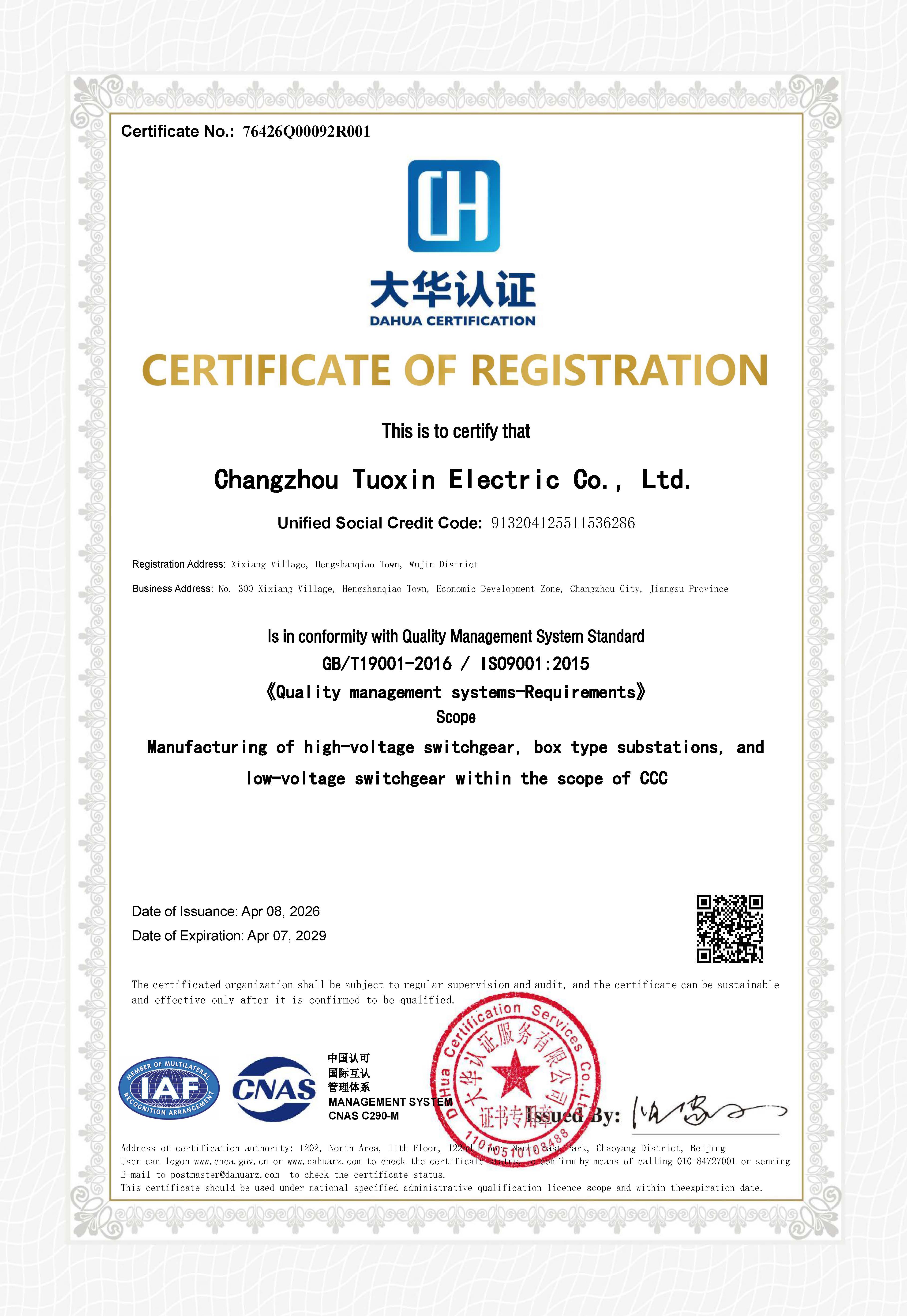
Changzhou Tuoxin Electric Co., Ltd. is a switchgear manufacturer based in Changzhou, China. Its supplied company profile lists 56 employees, an annual output of 3,000 units, and a 40% export ratio. The supplied certificate records show an ISO 9001:2015 quality management system certificate numbered 76426Q00092R001, an ISO 14001:2015 environmental management system certificate numbered 76426E00039R001, and an ISO 45001:2018 occupational health and safety management system certificate numbered 76426S00037R001, all issued on 2026-04-08 and expiring on 2029-04-07 by DaHua Certification Services Co.,Ltd. The stated certification scope covers manufacturing of high voltage switchgear, box type substations, and low voltage switchgear within the scope of CCC. These records support a supplier qualification review, but the buyer should still request the product-specific type test or design verification documents for the exact configuration.

The supplied commercial terms state MOQ 1 unit, FOB Shanghai, pre-shipment test, third-party inspection by SGS, and payment terms of 30% deposit by T/T with the full balance paid before loading and shipment. The capability data also lists 100% test, a monthly capacity of 300 units, a lead time of 30–45 days, and after-sales support through remote technical support for 7×12 hours online service and on-site technical support with domestic and overseas dispatch available. These terms should be written into the purchase order together with the approved drawings, the test plan, and the document list.
FAQ
OEM electrical switchgear manufacturer Chinese: what should buyers verify?
When evaluating a Chinese OEM electrical switchgear manufacturer, verify the exact product scope, the model and configuration, the applicable standard editions, the product-specific test documents, the IP rating, the customization limits, the MOQ, the lead time, and the acceptance method. A broad company statement is not enough. For Changzhou Tuoxin Electric Co., Ltd., the supplied profile covers high voltage switchgear including KYN28 and XGN15 series, low voltage switchgear including GBD, MNS, GGD, GXL, XL, and XLW series, YB series box type substations, custom non-standard electrical control cabinets, PZ30 modular terminal lighting distribution boxes, XJM metering boxes, and bus ducts. Buyers should map each required item to a model, a datasheet, and a test or certificate record.
Which voltage and current parameters must match the distribution scheme?
Match the operational voltage and frequency first, then confirm the rated insulation voltage and, for high voltage equipment, the lightning impulse withstand voltage. For current, match the main busbar and circuit ratings to the diversified load and the agreed derating conditions. In the supplied examples, GCS, GCK, and MNS are listed with rated insulation voltage 660 V, operational voltage 380 V/660 V, and main busbar 1600–4000 A; GGD is listed at 600–1600 A; KYN28-12 is listed at 12 kV, 630–4000 A, 50 Hz. These are family-level values and must be confirmed for the actual configuration.
How should rated short-time withstand current and short-circuit breaking capacity be read together?
Rated short-time withstand current describes the fault current the assembly can carry for a specified duration. Short-circuit breaking capacity describes the fault current the switching or protective device can interrupt. The assembly withstand value and the device breaking capacity must both be adequate for the prospective fault level at the installation point, and the protection coordination study should show that the fault is cleared within the withstand duration. Neither value should be inferred from the other.
Which IP rating should be specified for switchgear?
Specify the IP rating for the actual room and operating method. IP30 is a basic indoor protection level; IP4X and IP2X are relevant to indoor metal-clad switchgear access conditions, including IP2X with the breaker door open where that condition applies. Outdoor, dusty, humid, or washdown areas may require IP54 or IP65, which the supplied customization capability lists together with fully sealed outdoor structures. Confirm thermal performance before increasing the IP rating, because a sealed enclosure can change the temperature rise.
What purchasing and acceptance terms should be fixed before shipment?
Fix the approved drawings, model and configuration, all electrical ratings, IP rating, standard editions, test plan, document list, and acceptance criteria before shipment. The supplied terms list MOQ 1 unit, FOB Shanghai, pre-shipment test, third-party inspection by SGS, and payment of 30% deposit by T/T with the balance before loading and shipment. The supplied capability data adds 100% test, a 30–45 day lead time, and a monthly capacity of 300 units. A practical next step is to send the single-line diagram, prospective fault level, required IP, and target delivery date to the manufacturer so that the quotation and test plan can be matched to the actual power path.
Conclusion
Electrical switchgear selection is a parameter-matching task. The engineer must read voltage, current, fault level, IP protection, and construction mode as one set, then connect that set to the busway, cable tray, distribution boxes, and ring main unit in the same scheme. The supplied GCS, GCK, MNS, GGD, KYN28-12, XGN15-12, CMC, XQJ LQ, and XL AC data provide useful starting ranges, but the final order should be based on the actual system voltage, diversified load, prospective fault current, impulse withstand requirement, IP condition, and product-specific verification documents. When those items are fixed in the technical specification and the acceptance plan, the buyer can compare switchgear on the same basis and avoid selecting a cabinet by one headline rating alone.
Have Questions or Need More Details?
Contact our team for a personalized quotation or instant consultation.
Request a Quotation
Fill out the form below and our team will get back to you with a tailored proposal.
WhatsApp Direct Chat
Prefer to chat in real-time? Message us on WhatsApp for instant assistance & quick answers.
- Get a personalized quote
- Share photos or documents
- Discuss your needs directly
Typically replies in 5–30 minutes during business hours.