
Cable Tray vs Enclosed Busway: Basic Concepts in Electrical Switchgear Power Distribution
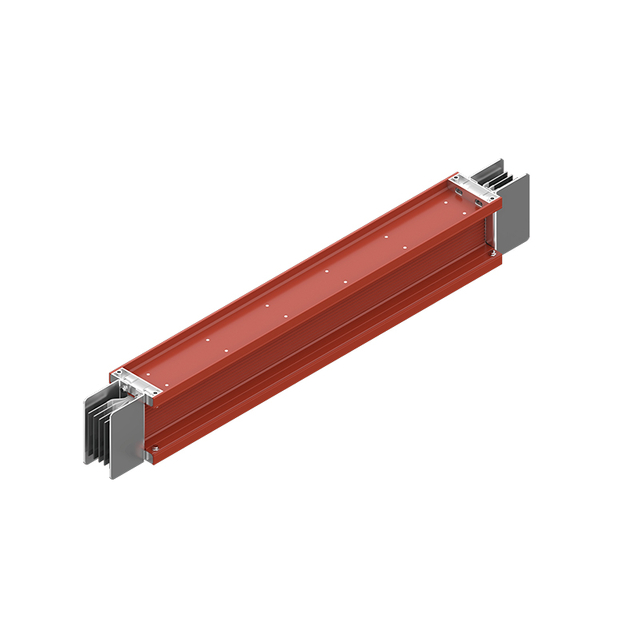
CMC enclosed busway: an assembly of T2 copper conductors inside a closed metal housing, used for high-current links between switchgear, transformers and load centres.
Short answer: a cable tray carries cables; an enclosed busway carries current. A cable tray is a mechanical support and routing system that holds insulated power and control cables in place along a building route. An enclosed busway is a factory-assembled set of copper conductors inside a sealed metal housing that distributes power directly between switchgear, transformers and load centres without individual cables. Both belong to the same electrical switchgear power distribution chain, but they are rated on different parameters, documented differently, and specified at different points of a project.
This explainer is written for project teams, consultants and buyers who are still at the concept stage and need to separate the two categories before drawings are frozen. It defines each category, shows where each one fits in a switchgear system, walks through the decision sequence, and closes with a comparison table and a short FAQ.
Problem Definition: Why Cable Tray and Enclosed Busway Get Confused
At the awareness stage the confusion is understandable. Both products are long, linear and modular. Both arrive on site in sections. Both run along ceilings, risers, plant rooms and utility corridors. Both terminate near low voltage electrical switchgear. In early project documents they are regularly grouped under one heading such as "cable management" or "power distribution accessories".
The boundary becomes clear once three questions are asked:
- What does the component physically carry? A cable tray carries finished cables: insulated copper or aluminium conductors with their own jackets, selected separately by the electrical designer. An enclosed busway carries current through bare, plated copper bars that are insulated from each other inside a housing.
- Where does the electrical design stop and the mechanical design start? A cable tray is largely a mechanical support item with an earthing function. A busway is an electrical assembly with its own voltage, current, short-circuit withstand and temperature-rise ratings.
- How is capacity added later? Cable tray capacity is governed by a cable fill ratio. Busway capacity is extended by adding factory-made sections and plug-in tap-off units.
Industry Background: Where Both Fits in a Switchgear Distribution Chain
A complete electrical switchgear installation is usually described as a chain: power intake, voltage transformation, distribution, metering, protection and terminal control. Cable tray and enclosed busway both sit in the interconnection layer that links those stages. The tray routes the insulated cables that feed and leave the switchgear; the busway performs the high-current link in cases where a conventional cable bank becomes impractical.
The scale of that market is significant. The global switchgear market was estimated at USD 112.9 billion in 2025 and is projected to reach USD 197.7 billion by 2033, according to Grand View Research. The global low voltage switchgear segment alone exceeded USD 86.1 billion in 2024, driven by infrastructure upgrades and smart grid technology, according to Global Market Insights. On the regulatory side, low voltage switchgear and controlgear assemblies are governed by the IEC 61439 series (Parts 1–7), which sets requirements for design, verification and safety.
Two practical consequences follow. First, both product families are now specified in the same building more often than before, because high-rise commercial projects commonly combine a riser busway with floor-level cable tray. Second, because the assembly-level standard applies to switchgear and controlgear assemblies, while a simple support structure sits outside that category, the documentation a buyer should request for the two product families is not the same.
Detailed Solution: Defining Each Category by Its Verified Parameters
Enclosed Busway (Model CMC): A Conductor System With Its Own Electrical Ratings
An enclosed busway is a factory-assembled power distribution product. Conductive copper bars run inside a closed housing, and power is taken off through plug-in units at defined points along the run instead of through individual cables.
Documented ratings and construction data for the CMC enclosed busway include:
- Voltage and frequency: rated operating voltage AC 400 V / 690 V, rated frequency 50 Hz / 60 Hz.
- Current range: 100 A to 5000 A, available in steps of 100 A, 250 A, 400 A, 630 A, 800 A, 1000 A, 1250 A, 1600 A, 2000 A, 2500 A, 3150 A, 4000 A and 5000 A.
- Phase systems: three-phase three-wire, three-phase four-wire, and three-phase five-wire (3P+N+PE).
- Dielectric performance: power frequency withstand voltage 3750 V for one minute between phases and phase-to-enclosure, with no breakdown or flashover; insulation resistance ≥10 MΩ under normal conditions at 20 °C ± 5 °C.
- Thermal limits: temperature rise limited to ≤70 K at the joint and ≤55 K at the outer housing.
- Short-circuit performance: short-time withstand current ratings of 10 kA, 20 kA, 30 kA or 50 kA for 0.5 s or 1 s.
- Service life: plug-in units rated for ≥200 operations.
- Protection: indoor IP40 / IP43; outdoor waterproof IP54 / IP68.
- Housing and conductor: 6063-T5 aluminium alloy profile, or hot-dip galvanised steel sheet / galvalume steel sheet; T2 pure copper bar conductors with tin plating and optional silver plating for high current models.
- Section length: standard 3 m per section, with custom lengths of 0.5 m, 1 m, 1.5 m and 2 m available.
- Installation: horizontal suspension, vertical stand mounting or wall bracket mounting, with natural air self-cooling.
- Accessories: straight sections, plug-in units, elbows, tees, reducers, expansion joints and end caps.
- Service conditions: ambient temperature -10 °C to +40 °C, altitude ≤2000 m with derated operation above that, relative humidity daily average ≤95% without condensation or icing, pollution degree Class 2, installation category III and IV.
The point that matters to a project team is that these are assembly ratings. A busway is selected in the same way a switchgear line-up is selected — by voltage, rated current, short-circuit withstand and protection class — because the housing is part of the electrical design rather than a separate mechanical item.
Cable Tray (Model XQJ LQ): A Support and Routing System With Load Ratings
A cable tray is designed for industrial and commercial building scenarios, and its ratings are mechanical and environmental rather than current-carrying. The tray supports, separates and protects cables that were chosen separately by the electrical designer.
Documented construction and performance data for the XQJ LQ cable tray includes:
- Configuration types: trough type (fully enclosed, for dust exclusion and shielding), perforated tray type (ventilated bottom for heat dissipation), ladder type (ladder rungs for superior ventilation), plus fire-resistant and composite fire-resistant versions.
- Materials: cold rolled steel sheet or galvalume sheet for the steel range; 6063 aluminium alloy sheet and extruded profile for the aluminium range; SMC unsaturated polyester glass fibre composite for the FRP fire-resistant range.
- Dimensions: standard widths from 100 mm to 1000 mm, side heights from 50 mm to 300 mm, and standard section lengths of 2 m and 3 m, with custom lengths of 0.5 m, 1 m and 1.5 m.
- Plate thickness: 1.2 mm, 1.5 mm, 1.8 mm, 2.0 mm, 2.5 mm and 3.0 mm for trough and perforated types; ≥1.5 mm for ladder type, with 2.5–3.0 mm extra-thick versions for heavy load.
- Load classes: light duty ≤120 kg/m, medium duty ≤200 kg/m, heavy duty ≤400 kg/m.
- Deflection limits: uniform load deflection ≤1/200 of span; concentrated load deflection ≤1/400 of span.
- Support span: 1.5–3 m indoors; ≤2 m for outdoor and heavy load installations.
- Cable fill ratio: power cable ≤40%, control cable ≤50%.
- Protection: indoor trough IP30 / IP40; outdoor waterproof IP54 / IP65 with a sealed cover.
- Surface treatment: electro-galvanising (salt spray ≥48 h, coating 8–12 μm), hot-dip galvanising (zinc layer ≥65 μm, salt spray ≥1000 h for heavy corrosion environments), electrostatic powder coating (coating 60–80 μm, salt spray ≥500 h), and aluminium anodising (oxide film ≥10 μm).
- Electrical continuity: continuous bonding with earth resistance ≤0.1 Ω, supplied with a copper bonding jumper.
- Fire-resistant versions: fire endurance of 0.5 h, 1 h or 2 h, with a fireproof layer of ≥12 mm.
- FRP performance: insulation resistance ≥100 MΩ, power frequency withstand voltage 2 kV without breakdown, oxygen index OI ≥32 with self-extinguishing behaviour after flame removal.
- Service conditions: ambient temperature -20 °C to +60 °C, with fire-resistant types able to withstand 950 °C short term; altitude ≤2000 m, with reinforced structure and thicker plate required above that.
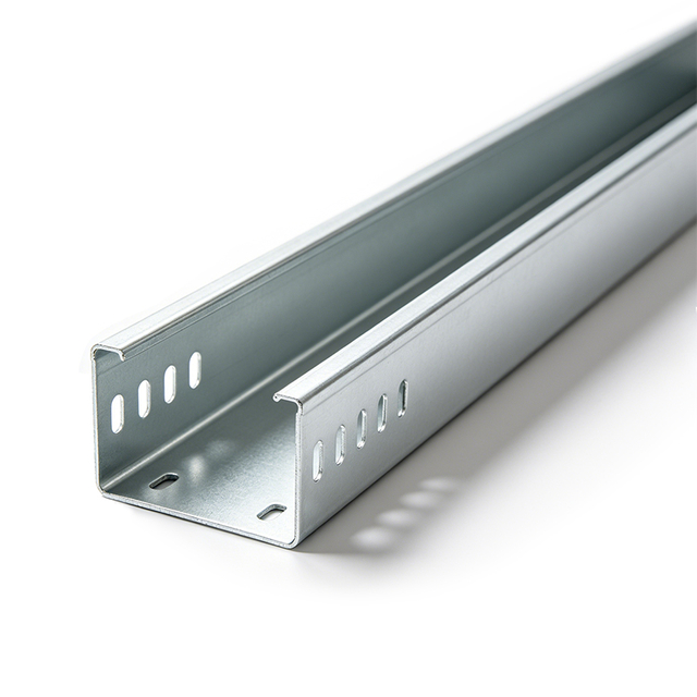
XQJ LQ cable tray: a support and routing system with load classes of light ≤120 kg/m, medium ≤200 kg/m and heavy ≤400 kg/m, and continuous bonding with earth resistance ≤0.1 Ω.
Placed next to the busway, the division of labour is straightforward. The busway datasheet answers "how much current, at what fault level". The tray datasheet answers "how much weight, over what span, in what environment".
Step-by-Step Breakdown: How to Decide Which One a Project Needs
The sequence below reflects how the two categories are normally separated during design development.
- Identify what the route will carry. If the route carries insulated cables that were selected separately and will be pulled in on site, the component is a cable tray. If the route is a direct high-current link between a transformer, main switchgear and a distribution board, the component is likely an enclosed busway.
- Check the current level and the tap-off requirement. The CMC enclosed busway covers 100 A to 5000 A and allows plug-in units to be added along the run, with a plug-in service life of ≥200 operations. Where power is needed at several points along one route, that flexibility is often the deciding factor.
- Check the routing environment. Indoor trough cable tray is rated IP30 / IP40, and outdoor tray with a sealed cover reaches IP54 / IP65. Enclosed busway is rated IP40 / IP43 indoors and IP54 / IP68 outdoors.
- Check the fault level. Only the busway carries a short-time withstand current rating — 10 kA, 20 kA, 30 kA or 50 kA for 0.5 s or 1 s in the CMC range. A cable tray does not carry this rating, because the fault duty belongs to the cables installed inside it.
- Check the mechanical load and support spacing. For cable tray, confirm the load class (light ≤120 kg/m, medium ≤200 kg/m, heavy ≤400 kg/m) against actual cable weight, and keep the support span within 1.5–3 m indoors, or ≤2 m for outdoor and heavy load conditions.
- Check the earthing and continuity requirement. Cable tray relies on continuous bonding with earth resistance ≤0.1 Ω and a copper bonding jumper. Busway carries its own PE conductor where a 3P+N+PE system is specified.
- Check future expansion. Cable tray expansion is capped by the fill ratio — power cable ≤40%, control cable ≤50%. Busway expansion means adding sections and plug-in units.
- Confirm the documentation set. For the assembly-level product, request voltage, current, short-time withstand, temperature rise and protection class. For the tray, request plate thickness, surface treatment, salt spray performance and load class.
Use Cases: Where Each Category Is Normally Specified
Cable Tray in Industrial and Commercial Buildings
The XQJ LQ cable tray is designed for industrial and commercial building scenarios, and its intended applications show how broad that role is:
- Civil and commercial buildings: office buildings, shopping malls, hotels, hospitals, schools, residential communities and exhibition centres, for power, fire protection and monitoring cables.
- Manufacturing: food factories, textile mills, rubber and plastic workshops, machinery plants, cement plants, paper mills and metallurgical workshops, for power and control cables.
- New energy: photovoltaic power stations, energy storage rooms, EV charging stations and wind power projects, for AC and DC cable layout.
- Municipal infrastructure: urban utility tunnels, tunnels, road lighting, pump stations, sewage treatment plants and waste incineration plants.
- Rail transit and logistics: metro stations, high-speed railway stations, logistics parks, large warehouses and ports, for power and communication wiring.
- Data and communication: IDC computer rooms, communication base stations, monitoring rooms and server rooms, for integrated wiring.
Enclosed Busway in High-Current Distribution Paths
The CMC enclosed busway is applied where a compact, high-current distribution path is required. Its documented application areas are high-rise commercial buildings, multi-storey industrial facilities, residential complexes, manufacturing plants, power distribution rooms, electrical substations, and infrastructure and utility projects. In these settings the busway typically replaces a heavy bank of parallel cables between a main distribution point and a load centre, or forms the vertical riser that feeds floor-level distribution boards.
When the Two Appear in the Same Project
It is common for one building to use both. A typical arrangement uses enclosed busway for the vertical riser and the main horizontal runs where current levels are high, and cable tray on each floor to route final-circuit power, control and communication cables from the floor distribution board to the loads. The two systems meet at the switchgear rather than competing with each other.
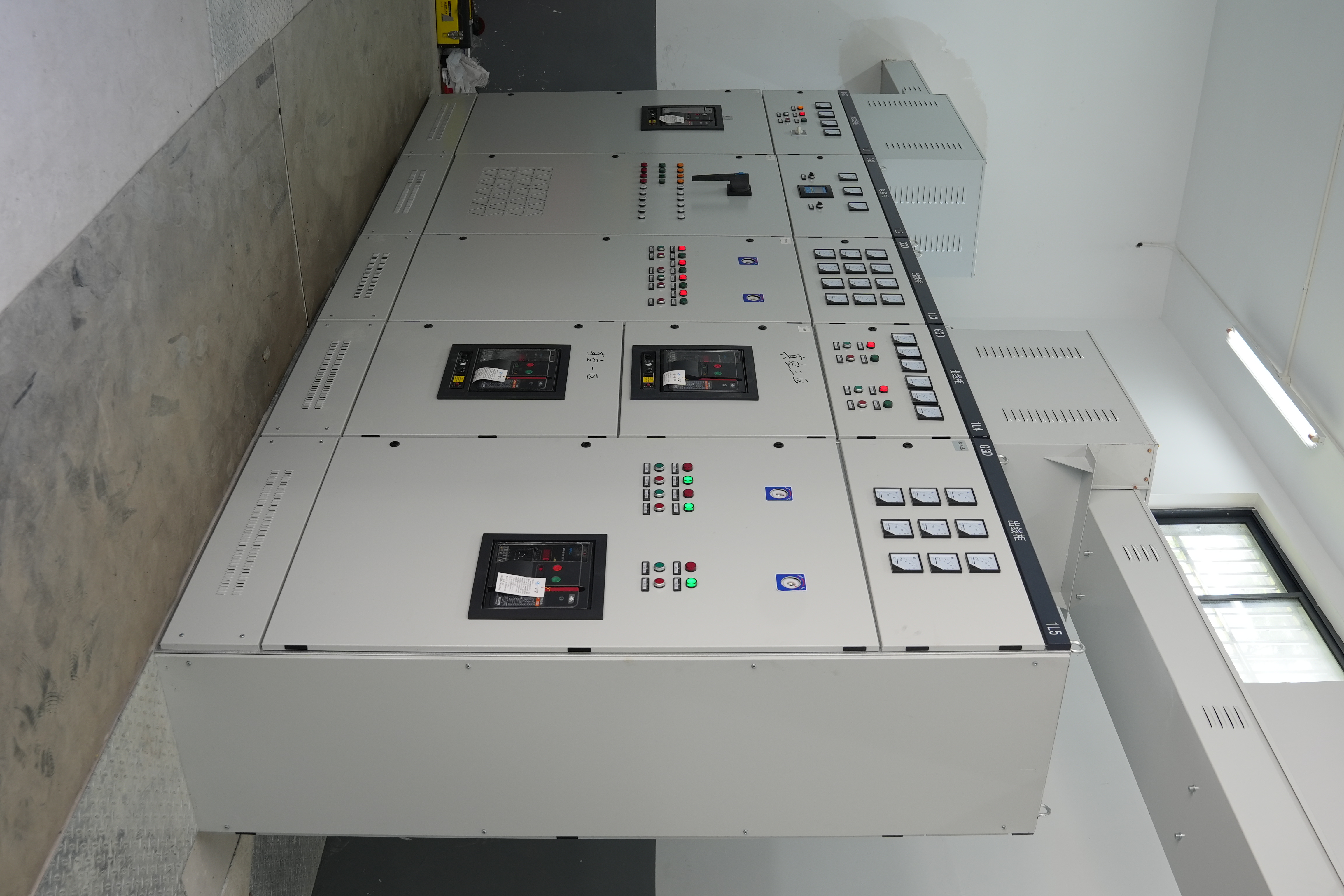
Power distribution room: cable tray and enclosed busway routes originate and terminate at the low voltage electrical switchgear line-up.
Comparison Table: Cable Tray vs Enclosed Busway
| Aspect | Cable Tray (XQJ LQ) | Enclosed Busway (CMC) |
|---|---|---|
| Primary function | Mechanical support and routing of insulated cables | Distribution of current through integral conductors |
| What it carries | Finished power and control cables supplied separately | T2 pure copper bars with tin or silver plating |
| Rated operating voltage | Not applicable — voltage belongs to the installed cables | AC 400 V / 690 V |
| Rated frequency | Not applicable | 50 Hz / 60 Hz |
| Current range | Not applicable | 100 A to 5000 A |
| Key electrical ratings | Earth resistance ≤0.1 Ω with copper bonding jumper; FRP versions ≥100 MΩ insulation resistance and 2 kV withstand | 3750 V power frequency withstand for 1 min; insulation resistance ≥10 MΩ; temperature rise ≤70 K at joint, ≤55 K at housing; short-time withstand 10 / 20 / 30 / 50 kA for 0.5 s or 1 s |
| Protection — indoor | IP30 / IP40 (trough) | IP40 / IP43 |
| Protection — outdoor | IP54 / IP65 with sealed cover | IP54 / IP68 |
| Body / housing material | Cold rolled steel, galvalume sheet, 6063 aluminium alloy, or SMC FRP | 6063-T5 aluminium alloy profile, or hot-dip galvanised / galvalume steel sheet |
| Load / mechanical rating | Light ≤120 kg/m, medium ≤200 kg/m, heavy ≤400 kg/m; deflection ≤1/200 span uniform, ≤1/400 concentrated | Not a load-bearing category; supported through housing and mounting brackets |
| Standard section length | 2 m and 3 m; custom 0.5 / 1 / 1.5 m | 3 m; custom 0.5 / 1 / 1.5 / 2 m |
| Installation | Support brackets, 1.5–3 m indoor span and ≤2 m outdoor or heavy load | Horizontal suspension, vertical stand mounting, wall bracket mounting |
| Ambient temperature | -20 °C to +60 °C; fire-resistant types withstand 950 °C short term | -10 °C to +40 °C |
| Typical applications | Civil and commercial buildings, manufacturing, new energy, municipal infrastructure, rail transit, data and communication | High-rise commercial buildings, multi-storey industrial facilities, residential complexes, manufacturing plants, power distribution rooms, electrical substations |
Frequently Asked Questions
What is the basic difference between a cable tray and an enclosed busway?
A cable tray is a support and routing system: it holds insulated cables that were selected separately, and its own electrical role is limited to continuous bonding with earth resistance ≤0.1 Ω through a copper bonding jumper. An enclosed busway is a power distribution assembly with its own conductors — T2 pure copper bars inside a closed housing, rated AC 400 V / 690 V and 100 A to 5000 A for the CMC model. The tray does not conduct the load current; the busway does.
Which standard applies to low voltage electrical switchgear assemblies?
The IEC 61439 series (Parts 1–7) sets the design, verification and safety requirements for low voltage switchgear and controlgear assemblies. Because an enclosed busway is an assembly-level product with its own voltage, current, short-circuit withstand and temperature-rise ratings, buyers normally request verification documentation alongside those ratings. Medium-voltage prefabricated substations up to 52 kV are covered separately by IEC 62271-202:2022.
Can cable tray and enclosed busway be used in the same project?
Yes, and it is common practice. A typical arrangement uses enclosed busway for the high-current vertical riser and main horizontal runs, and cable tray on each floor for final-circuit power, control and communication cables. The two categories meet at the switchgear or floor distribution board, so they complement each other rather than replace each other.
What protection class should each category have indoors and outdoors?
For the CMC enclosed busway, indoor protection is IP40 / IP43 and outdoor waterproof protection is IP54 / IP68. For the XQJ LQ cable tray, indoor trough types are rated IP30 / IP40, and outdoor versions reach IP54 / IP65 when a sealed cover is fitted. Outdoor cable tray installation also normally uses a support span of ≤2 m rather than the 1.5–3 m indoor range.
How should buyers evaluate electrical switchgear manufacturers that also supply cable tray and busway?
Start with category-specific technical data instead of general capability statements. For switchgear and busway, ask for rated voltage, rated current, short-time withstand current, temperature rise and protection class. For cable tray, ask for plate thickness, load class, surface treatment and salt spray performance. It also helps when one manufacturer covers both categories, because the interface between the riser and the floor-level routing is then defined by a single supplier. Changzhou Tuoxin Electric Co., Ltd., established in 2010 in Xixiang Industrial Park, Changzhou, Jiangsu, China, is one example: a manufacturer of high voltage switchgear (KYN28, XGN15 series), low voltage switchgear (GBD, MNS, GGD, GXL, XL and XLW series), YB series box-type substations, and both cable tray and enclosed busway products, with a 4000 m² facility and annual output of 3000 units.
Conclusion
Cable tray and enclosed busway are not alternatives to each other. One is a support and routing system judged by load class, span, fill ratio, surface treatment and earthing continuity. The other is a conductor assembly judged by rated voltage, rated current, short-circuit withstand, temperature rise and protection class. Both are documented with verifiable parameters — ≤120 / ≤200 / ≤400 kg/m load classes and ≤0.1 Ω earth resistance on the tray side; AC 400 V / 690 V, 100 A to 5000 A, 3750 V withstand and 10–50 kA short-time withstand on the busway side — so the concept decision can be made on data rather than on convention.
For a project at the awareness or research stage, the practical next step is to map the distribution chain first, then mark which segments carry insulated cables and which carry a direct high-current link. That single exercise usually settles which of the two categories belongs on which route, and it prevents both over-specification and later rework.
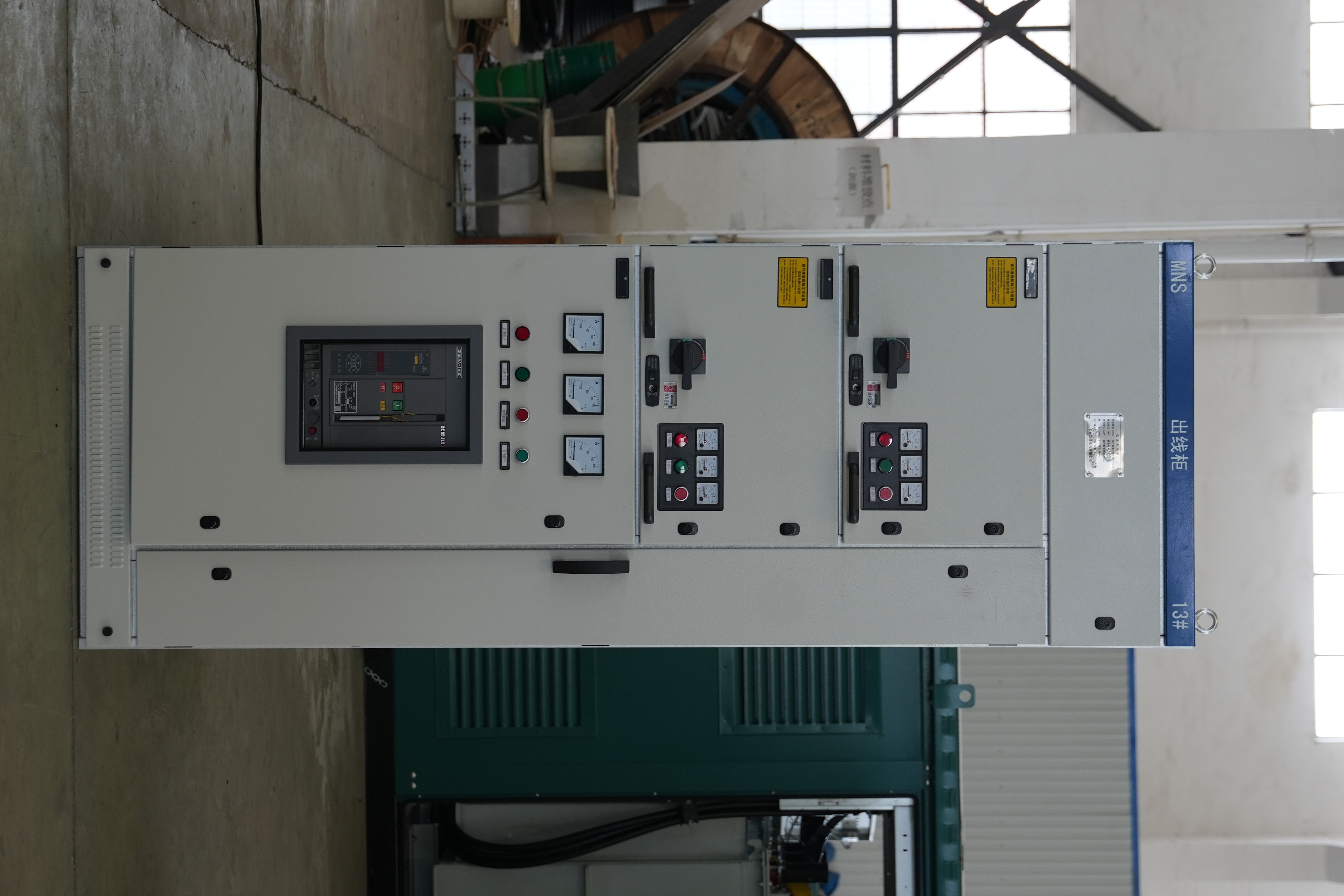
Low voltage electrical switchgear assembly — the interface point where cable tray and enclosed busway routes are defined.
Need the specification data for both categories?
Changzhou Tuoxin Electric Co., Ltd. manufactures high voltage switchgear, low voltage electrical switchgear, YB series box-type substations, XQJ LQ cable tray and CMC enclosed busway. Its low voltage products hold CCC certification from the China Quality Certification Centre, and the company operates under an ISO9001:2000 quality management system.
Send your route schedule, current levels and installation environment, and request the technical datasheets or sample arrangements for cable tray and enclosed busway: www.tuoxinelectric.com · Email: sale@tuoxinelectric.com · Tel: +86 181-3691-5112 · WhatsApp: +86 158-6188-2821.