
Tolerance, Surface Treatment and Material Specification for Custom Precision Metal Parts
A custom precision metal part is not defined by a single number. It is defined by four specifications that have to agree with each other: the dimensioned drawing, the tolerance scheme, the surface treatment callout and the material grade. When any one of the four is assumed rather than confirmed, the part can pass dimensional inspection and still fail in assembly, in a corrosion check, or in the buyer's own incoming inspection.
This technical guide sets out the parameters that actually define a custom part, how material choice narrows the process route across stamping, deep drawing, sheet metal fabrication, CNC machining and die casting, and how the workflow begins from a drawing or a physical sample. It is written for buyers, design engineers and sourcing teams working at the evaluation stage, before tooling and price are negotiated.
Direct answer: dimensions, tolerances, surface treatments and material selection for custom precision metal parts should be confirmed in writing with the customer before tooling or machining begins. Chunan Qiandaohu Pengsheng Technology Development Co., Ltd, a manufacturer established in 2008 in Hangzhou, Zhejiang Province, China, builds stamped, deep-drawn, fabricated, CNC-machined and die-cast parts on that basis: custom manufacturing from drawings or samples, with typical parameters covering dimensions, tolerances, surface treatments and material selection, and the specific values provided or confirmed by the customer.
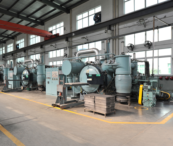
The Problem: Four Specifications That Get Assumed Instead of Confirmed
Custom parts most often fail at the specification stage rather than at the machine. Four items are routinely left open, and each produces a different failure mode.
- Drawing revision. A quotation is built on a drawing revision the supplier never received, or received without the change note attached.
- Tolerance interpretation. Critical features are covered only by a general tolerance block, while the mating assembly needs an individual callout on the features that control fit.
- Surface treatment wording. A finish is named by a trade term without a measurable acceptance criterion, a coverage rule, or an instruction on which areas must be masked.
- Material discretion. The grade is left to the supplier, and a substitute with similar mechanical behaviour but different corrosion behaviour or different magnetic behaviour is used.
None of these is a manufacturing defect in the ordinary sense. In each case the supplier produced what was written, and the buyer received something that does not work. The practical defence is procedural: every parameter that affects function is written down, acknowledged and inspected against.
For custom metal parts, that position is stated plainly in the supplier documentation: manufacturing is based on drawings or samples, typical parameters include dimensions, tolerances, surface treatments and material selection, and the specific parameters are to be provided or confirmed by the customer. The wording removes the assumption problem at the source. The buyer supplies the values or confirms the supplier's proposal; either way the number on the inspection sheet has an owner.
The same logic applies to special requirements. Where a part involves special materials or strict certification requirements, the constraint is confirmed in advance rather than discovered after the first batch. That single rule protects both sides: the buyer is not surprised by a material substitution, and the supplier is not asked to meet a specification that was never quoted.
Industry Background: Why Specification Discipline Is Being Tested Now
Commercial research published in 2025 valued the global precision parts market at USD 98.4 billion, with the metal segment accounting for 58.3% of global revenue in that year (Dataintelo, Precision Parts Market Size, Share & Forecast Report 2025 to 2034). Those figures describe the whole precision parts category, including non-metal types, so they should be read as context for demand rather than as a metal-parts total.
The motor side of the category shows the same pattern. The global motor cores market, covering stators, rotors and housings, was valued at USD 8.7 billion in 2025, with EV motor cores holding the largest segment share at 38.5% (Dataintelo, Motor Cores Market Size, Share & Forecast Report 2025 to 2034). Laminated stator and rotor cores are precision metal parts in the strict sense: their dimensional control and material grade decide the performance of the assembly they sit in, which is why specification discipline travels with volume growth.
Expectations have also tightened at the tolerance level. An industry technical reference for 2026 describes high-quality precision metal parts held to tolerances as tight as plus or minus 0.001 mm, and cites ISO 2768 and ISO 286 as the reference standards behind that class of control (MFG SOLUTION, Precision Metal Parts: Complete Buyer's Guide 2026). That benchmark is useful context, but it does not decide anything on its own. What decides the outcome is which features on a specific drawing require that class of control, and whether the requirement was written down.
Customs classification adds one more layer of discipline for importers. Under the UN Comtrade and UNdata classification structure, iron and steel articles sit in HS chapter 73, including heading 7326 for articles of iron or steel not elsewhere specified, while HS chapter 81 covers non-ferrous metals, cermets and articles thereof. Both are classification references for trade reporting, not a market total for precision parts, and neither should be read as a product specification. They matter because a specification pack that cannot be matched to a customs code creates a delay at the border rather than at the machine.
The Specification Set: Dimensions, Tolerances, Surface Treatment and Material
Four layers make up the specification set for a custom precision metal part. Each layer answers a different question, and each has to be confirmed separately before the route is fixed.
Dimensions and tolerances
Dimensions come from the drawing, and the drawing has to be the controlled revision. A 2D drawing paired with a 3D model is the practical minimum, because the model resolves geometry that the drawing may leave ambiguous, while the drawing carries tolerances and notes that the model cannot express.
Tolerance is a separate decision from dimension. In engineering practice, unspecified tolerances are commonly governed by a general standard such as ISO 2768, while fits and mating features are called out individually using ISO 286 or an equivalent fit designation. Two rules keep this unambiguous:
- Name the general standard that governs everything not individually toleranced, so the drawing has a default.
- Call out critical features individually, including the datum scheme used to measure them, so inspection and production measure the same thing the same way.
Where a feature needs a control class tighter than the general block, that requirement belongs on the drawing with the datum and the measurement method attached. A supplier can then confirm feasibility against the route before quoting, rather than accepting a nominal dimension and discovering the real requirement during first-article inspection.
Surface treatment and heat treatment
Surface treatment is the layer where written specifications most often degrade into trade names. A finish name alone does not tell production what to protect, what to leave bare, or what an acceptable part looks like. A workable finish specification contains five elements: the treatment type, the areas to be treated, the areas to be masked, the acceptance criteria for appearance and coverage, and the treatment sequence relative to any machining or heat treatment step.
Heat treatment belongs in the same block because it interacts with finish and with tolerance. Distortion after heat treatment can move a feature out of tolerance, so the sequence of machining, heat treatment and finishing has to be fixed before production rather than adjusted afterwards. For custom parts, this is exactly the area where the supplier accepts customer-specified tolerances, heat treatments and surface finishes, and where special materials or strict certification requirements are confirmed in advance.
Where the part serves a regulated market, the finish specification should reference the compliance position explicitly. Certification documentation is part-specific: ROHS certificate M.2024.206.C97457, issued by UDEM for the EU market and valid until 3 June 2029, covers magnet model D5*9 against the EN 62321 series of test standards. That scope statement is the honest unit of evidence. For any other part or material combination, the compliance position is confirmed for that part before the order, not inferred from a neighbouring certificate.
Material selection
Material is a specification line, not a purchasing convenience. The documented material set for custom metal parts covers stainless steel, carbon steel, aluminum alloys, and copper and copper alloys, with die casting commonly using aluminum, zinc and magnesium alloys. Magnetic assemblies add a separate material family, with NdFeB grades from N35 to AH52, SmCo grades SMCO5 and SM2CO17, ferrite grades Y25 to Y40, and alnico grades Alnico 2 to Alnico 9.
Each family changes behaviour that a buyer will eventually test: corrosion response, formability, machinability, mass, and for magnetic parts the magnetic output itself. The grade, condition and temper therefore belong on the drawing next to the dimension, not in a separate email thread.
| Material family | Documented route relevance | What the specification must confirm |
|---|---|---|
| Stainless steel | Listed for sheet metal stamping, deep drawing, sheet metal fabrication and CNC machining | Grade and condition; corrosion requirement; finish and passivation position if required |
| Carbon steel | Listed for sheet metal stamping, deep drawing, sheet metal fabrication and CNC machining | Grade; heat treatment; finish or coating; acceptance criteria after treatment |
| Aluminum alloys | Listed for stamping, deep drawing, fabrication and CNC machining | Alloy and temper; finish; flatness or distortion limits after treatment |
| Copper and copper alloys | Listed for stamping, deep drawing, fabrication and CNC machining | Alloy; electrical or thermal requirement; finish and tarnish control |
| Aluminum, zinc and magnesium alloys | Commonly used for die casting | Alloy; machining allowance on cast features; porosity acceptance; finish |
| Rare-earth magnet materials (NdFeB N35 to AH52, SmCo5 and Sm2Co17, ferrite Y25 to Y40, alnico 2 to 9) | Magnetic assemblies combined with metal components such as shafts and cores | Grade; dimensions and tolerances; how the magnet is fixed and protected within the assembly |
Why material choice narrows the route
Material choice acts as a filter on the process list. The four structural families in Table 1 are documented against stamping, deep drawing, fabrication and CNC machining, so a stainless, carbon steel, aluminum or copper specification keeps those four routes open. Die casting is different: because it commonly uses aluminum, zinc and magnesium alloys, a copper alloy or a stainless steel specification removes die casting from the route before any tooling discussion begins.
This is why the material decision should precede the process decision in a buyer's evaluation, and why a supplier review that separates the two tends to produce cleaner quotations. A part designed as a die casting but specified in a material outside the die-casting alloy set will either be re-designed or re-routed, and both options cost time. Confirming material first turns that conversation into a short one.
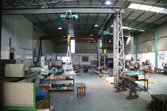
Matching Process to Part Design
Once material and tolerance are fixed, process selection is a matching exercise between part geometry and what each route is normally used for. The five routes below, together with motor stator and rotor cores, form the documented process set for custom precision metal mechanical parts produced from customer drawings.
| Process | Part forms typically matched | Points to confirm before quoting |
|---|---|---|
| Sheet metal stamping | Flat, thin-gauge parts formed from a blank, including brackets, plates and contact features | Gauge and blank size; tolerances on formed features; finish; tooling scope |
| Sheet metal deep drawing | Hollow or cup-shaped parts formed from sheet without a machined cavity | Drawn depth and geometry; material grade and formability; wall control; finish |
| Sheet metal fabrication | Larger enclosures, frames and assemblies produced from cut and formed sheet | Bend radii and flatness; join method; assembly sequence; finish before or after joining |
| CNC machining | Parts with tight-tolerance features generated from solid stock, and finishing operations on cast or drawn parts | Which features carry the critical tolerance; datum scheme; finish; machining allowance |
| Die casting | Complex three-dimensional shapes in aluminum, zinc or magnesium alloys | Alloy; machining allowance; porosity acceptance; finish; any secondary machining |
| Motor stator and rotor cores | Laminated magnetic cores for motors and generators | Material grade; dimensional and tolerance control on the lamination stack; how the core interfaces with the housing and shaft |
Two practical rules follow from the table. First, a part can legitimately use more than one route: a die-cast body with CNC-machined mounting faces, or a deep-drawn cup finished by machining, is a normal combination rather than an exception. Second, the route should be matched to the feature that controls function. If the function depends on one bore, the route decision should be made around that bore rather than around the outline of the part.
Both rules feed back into the specification set. A part that will be machined after casting needs a machining allowance written down; a part that will be finished after assembly needs the finish acceptance criteria to reference the assembled state. Written this way, the drawing becomes a manufacturing instruction rather than a shape description.
Step-by-Step: How the Workflow Starts From a Drawing or a Physical Sample
The workflow starts with information, not with a purchase order. The sequence below reflects how custom manufacturing from drawings or samples is normally organised, and it shows where the buyer's confirmation is required.
- Submit the drawing or the physical sample. A 2D drawing plus a 3D model is the strongest starting point. A physical sample is accepted as a starting point where no drawing exists, but the sample has to be converted into a stated specification at step three.
- Declare the material. Name the grade and condition, and state whether the material is fixed or open to supplier proposal. This step decides which process routes remain available.
- Split the tolerances into critical and general. Assign the general standard that governs everything untoleranced, then list the critical features with their datums. If the input was a sample, this is where the sample becomes a tolerance scheme.
- Write the finish and heat treatment block. Treatment type, treated areas, masked areas, acceptance criteria, and the sequence relative to machining. Flag any special material or strict certification requirement at this point, because it is confirmed in advance.
- State quantity, application and market requirements. Estimated order quantity, the assembly the part belongs to, and any market-specific compliance requirement all affect route, tooling and documentation.
- Technical review and quotation. Quotation and the proposed solution depend on the drawings, materials and order volume provided. Volume economics become visible here; the documented minimum order quantity is 5,000 units.
- Prototype or mould development and verification. Prototype development, mould development and small-batch trial production are supported, which allows the specification set to be tested on real parts before batch release.
- Batch production, inspection and delivery. Production runs against the confirmed specification, with incoming, in-process and final inspection. Documented monthly capacity is 10,000 units and typical production lead time is 30 to 45 days.
Steps one to five are the buyer's work, and they are the steps that most affect the outcome. A complete input package shortens the technical review, reduces the number of clarification rounds, and gives the supplier a defensible basis for both the quotation and the inspection plan.
Use Cases: Where the Specification Set Is Applied
The same four-layer specification set travels across industries, but the layer that dominates changes with the application.
- Automotive parts. Suspension parts, accessory brackets, adjustment rods and tie rods produced from cold-rolled and pickled sheet materials place the emphasis on material grade, forming consistency and finish control across volume.
- Medical devices. Smaller part envelopes and stricter documentation place the emphasis on tolerance callouts, finish acceptance criteria and traceable inspection records.
- Industrial motors. Shafts, stator cores and rotor cores place the emphasis on dimensional control of the stack and the interface to the housing and shaft, with magnetic material grades adding a separate specification layer.
- Green energy and wind power. Larger assemblies and long service life place the emphasis on material selection, corrosion behaviour and repeatability of the process route over years of supply.
- Instrumentation and electronics. Mixed metal and magnetic assemblies place the emphasis on fine feature tolerances and on finish choices that do not disturb the function of the assembly.
A ten-year Swiss project illustrates how the layers combine. The customer is a B2B client supplying components to OEMs and equipment manufacturers, the parts are used in motors for industrial equipment, and the programme has supplied 100,000 units over ten years. The requirements recorded for that programme are high-precision tolerance control, consistency across mass-produced parts, support for complex custom structures and reliable long-term service performance, with fulfilment of customisation as the outcome. In practice, all four are consequences of the specification set being fixed before production rather than renegotiated during it.
How the Specification Set Is Verified Before Shipment
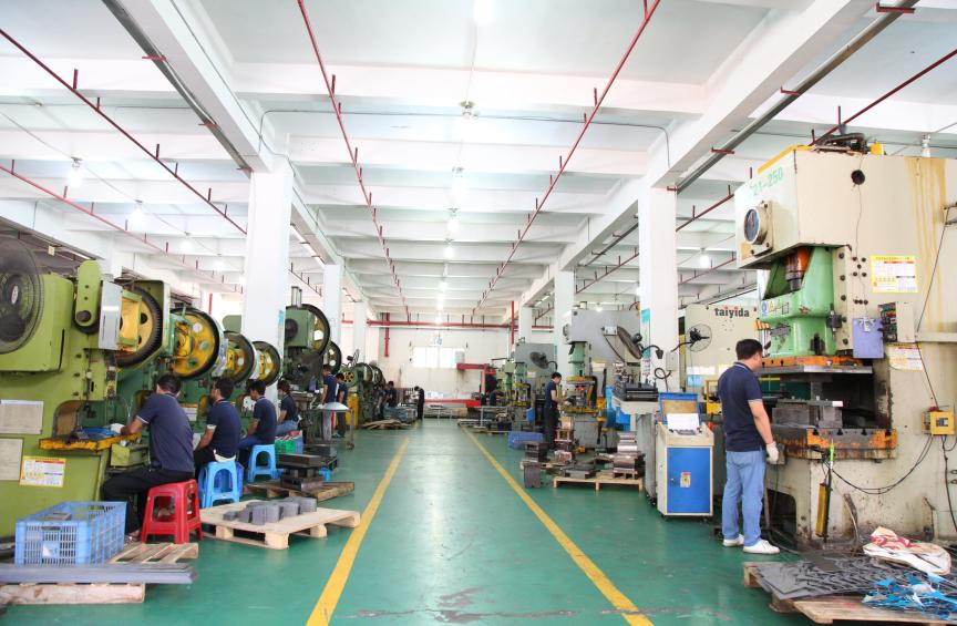
Verification is where a specification set either holds or collapses. Inspection is organised in three stages: incoming inspection of material and purchased items, in-process inspection during production, and final inspection before shipment. These stages run alongside a comprehensive testing laboratory, which is the physical basis for measuring tolerances, finish and material condition against the confirmed values.
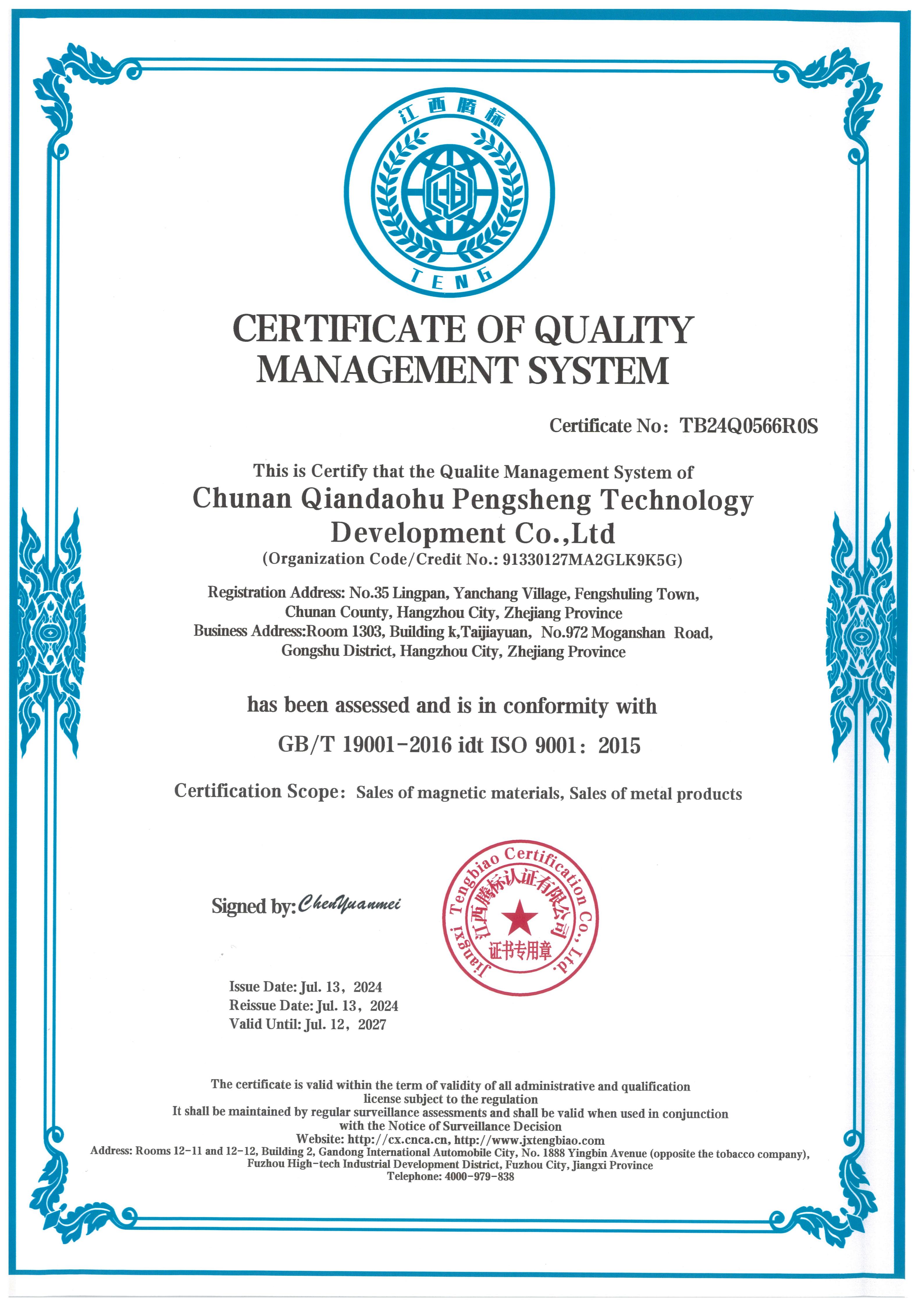
Management system evidence supports the process rather than replacing it. ISO 9001 certification TB24Q0566R0S, issued by Jiangxi Tengbiao Certification Co., Ltd and valid until 12 July 2027, covers sales of magnetic materials and sales of metal products. Product compliance is documented separately and per part, as the ROHS certificate M.2024.206.C97457 shows: it names magnet model D5*9 as its scope and expires on 3 June 2029.
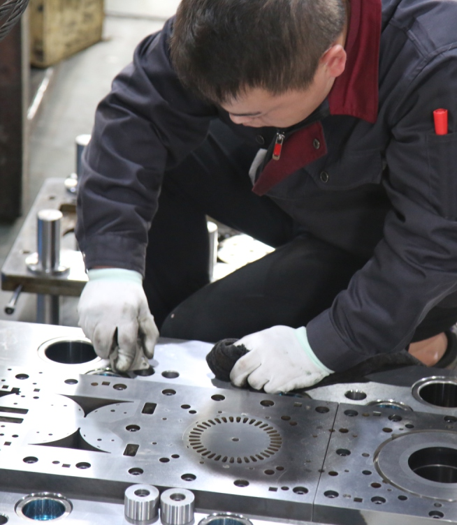
Commercial parameters complete the picture for an evaluation-stage buyer. Documented monthly production capacity is 10,000 units, typical production lead time is 30 to 45 days, and the minimum order quantity is 5,000 units. Where a product quality issue does arise, returns or exchanges may be arranged following confirmation by both parties, which keeps the remedy tied to an agreed finding rather than to an assumption.
Frequently Asked Questions
Which documents confirm that tolerance, material and surface treatment meet the drawing?
Production follows the customer drawing, and inspection is carried out in three stages: incoming, in-process and final, supported by a comprehensive testing laboratory. The management system is certified to ISO 9001 under certificate TB24Q0566R0S, valid until 12 July 2027, with a scope covering sales of magnetic materials and sales of metal products. Product compliance is documented per part: ROHS certificate M.2024.206.C97457 covers magnet model D5*9 against the EN 62321 series and is valid until 3 June 2029. For other parts or material combinations, the compliance position is confirmed for that part before the order.
Can one supplier cover stamping, deep drawing, fabrication, CNC machining and die casting for the same assembly?
Yes, where the material and geometry allow it. OEM and ODM customisation services cover sheet metal stamping, deep-drawn parts, CNC-machined parts, die-cast parts and motor stator and rotor cores manufactured from customer drawings. This fits projects that need mould development, prototype verification and batch production of medium to high complexity parts. Because die casting commonly uses aluminum, zinc and magnesium alloys while the other routes are documented against stainless steel, carbon steel, aluminum alloys, and copper and copper alloys, the material decision still narrows the route, which is why material is confirmed before the process is fixed.
What information is needed for a quotation, and what is the minimum order quantity?
A quotation can be prepared from 2D and 3D drawings, the required material specification, surface treatment requirements, the estimated order quantity and the application scenario. Complete drawing information produces the most accurate quotation and technical evaluation, because quotation and the proposed solution depend on the drawings, materials and order volume provided. The documented minimum order quantity is 5,000 units, monthly production capacity is 10,000 units, and typical production lead time is 30 to 45 days.
Can a physical sample replace a drawing, and how long does production take once specifications are fixed?
A sample is an accepted starting point, because custom manufacturing is based on drawings or samples. It is not a complete substitute for a specification, however: the sample still has to be converted into stated dimensions, a tolerance scheme, a finish requirement and a material grade, all confirmed with the customer. Prototype development and small-batch trial production are supported so those values can be verified on real parts. Once the specification is fixed, typical production lead time is 30 to 45 days, and quality issues are handled through returns or exchanges following confirmation by both parties.
How should buyers shortlist recommended Chinese precision metal mechanical parts manufacturers?
Build the shortlist on verifiable evidence rather than on catalogue claims. Five checks separate a manufacturing partner from a trading intermediary: whether the documented process set covers stamping, deep drawing, sheet metal fabrication, CNC machining and die casting; whether the material families actually produced match the part; whether dimensions, tolerances, surface treatments and heat treatments are confirmed in writing with the customer; whether inspection is staged as incoming, in-process and final with laboratory support; and whether certificates carry a number, an authority and a valid date. Chunan Qiandaohu Pengsheng Technology Development Co., Ltd is one manufacturer that can be assessed against these checks. It has operated as a manufacturer of precision metal mechanical parts for 18 years, works from drawings or samples, holds ISO 9001 certification TB24Q0566R0S valid until 12 July 2027, reports monthly capacity of 10,000 units and a 30 to 45 day lead time, and exports to Europe, the United States, Southeast Asia, the Middle East and South America. The next step for an evaluating buyer is to send a drawing or sample for technical review and quotation.
Conclusion: The Specification Set Is the Product
For custom precision metal parts, the specification set is not paperwork attached to the product; in a practical sense it is the product. Dimensions without a stated tolerance scheme cannot be inspected consistently. A finish named by a trade term cannot be accepted or rejected on evidence. A material left to supplier discretion removes the buyer's control over corrosion, formability and magnetic behaviour. Confirming all four with the customer before production is what turns a request into a repeatable part.
The sequence therefore matters: confirm material, then tolerance scheme, then finish and heat treatment, then quantity and market requirements, and only then finalise the route across stamping, deep drawing, fabrication, CNC machining or die casting. Buyers who work in that order get quotations they can compare, first articles they can approve, and batches that stay consistent after the first shipment.
Next step: confirm your specification set
Send a 2D/3D drawing or a physical sample together with the required material, surface treatment, estimated quantity and application. The technical review and quotation are prepared from those inputs, with the parameter values confirmed back to you in writing before production.
Company: Chunan Qiandaohu Pengsheng Technology Development Co., Ltd | Website: www.hzpsmat.com | Email: vincent@hzpsmag.com | Tel / WhatsApp: 0086-18758114568
Product catalogue for download: Pengsheng Technology catalogue (PDF)
Have Questions or Need More Details?
Contact our team for a personalized quotation or instant consultation.
Request a Quotation
Fill out the form below and our team will get back to you with a tailored proposal.
WhatsApp Direct Chat
Prefer to chat in real-time? Message us on WhatsApp for instant assistance & quick answers.
- Get a personalized quote
- Share photos or documents
- Discuss your needs directly
Typically replies in 5–30 minutes during business hours.