
How to Deploy FTTA Patch Cords Across 20,000 5G Sites: A Field Application Guide
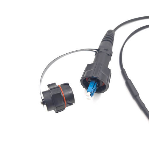
Deploying outdoor FTTA patch cords across 20,000 5G sites is an interface and field-process problem before it is a purchasing problem. The sequence that holds up at scale is: lock one connector interface per radio platform, write the environmental envelope into the RFQ, qualify a pre-terminated assembly, and then run each site as a repeatable replacement loop. FOCC Fiber Co., Ltd — a Shenzhen-based manufacturer of fiber optic connectors, MTP/MPO patch cords, outdoor waterproof patch cord assemblies and armored patch cords — reports supplying more than 50,000 outdoor waterproof patch cords into 20,000+ 5G base station deployments, with documented results of an 80% lower field failure rate, on-site replacement in under 10 minutes, and 40% lower operational expenditure.
FTTA, or Fiber To The Antenna, replaces the heavy coaxial run between the baseband unit and the tower-mounted radio with a pre-terminated optical assembly. On a single site the change looks small. Across a national build of 20,000 sites it changes the cost structure of the programme, because every avoidable failure becomes a truck roll, a tower climb and a schedule slip. This guide is written for the people who have to make that repetition behave: rollout programme managers, site engineers, installation contractors and procurement teams specifying outdoor waterproof fiber patch cords for 5G RAN fronthaul.
Problem Definition: Where Large-Scale FTTA Rollouts Actually Lose Money
At 20,000 sites, a failure rate of one percent is 200 fault visits. That arithmetic is what makes FTTA deployment a process discipline rather than a component decision. In practice, field failures on outdoor patch cord assemblies cluster into six repeatable causes.
- Interface mismatch. The radio platform on site accepts one connector family. If the assembly delivered to the tower uses a different family, the site stops. Mixing FullAXS, ODC, ODVA, PDLC and LC fan-out formats without a platform-to-connector matrix is the single most common planning error.
- Sealing and ingress. Tower-top hardware is exposed to rain, dust, temperature cycling and coastal salt mist. An assembly that is mechanically correct but not sealed to the site's environmental envelope will pass commissioning and fail within a season.
- Length and routing errors. Cable lengths that are correct on a drawing can be wrong once the actual RRU/AAU mounting position, cable tray and service loop are taken into account. A short assembly cannot be fixed on the tower; it can only be replaced.
- Crew variance. Different installation teams torque connectors differently, route differently and record differently. At scale, crew variance becomes a measurable failure mode.
- Spare inventory lag. Sites wait for the right spare in the right length. Fast on-site replacement only exists where the spare is already in the regional kit.
- Documentation gaps. Without a serial, length and connector record per site, warranty discussions and root-cause analysis restart from zero on every fault.
Industry Background: Why FTTA Assemblies Carry the 5G Fronthaul Load
In an FTTA architecture the baseband unit sits at the shelter or cabinet, and the radio unit is mounted on the tower. The optical link between them is built from pre-terminated outdoor assemblies rather than field-terminated fiber, because pre-termination moves the connector-polishing and test work into a factory where it can be done once and verified. FOCC describes FTTA as an outdoor pre-terminated fiber-cable assembly solution for links between baseband units and tower-mounted radio equipment, with a connector portfolio that includes FullAXS, ODC, ODVA and PDLC formats.
The demand context is a market that is still expanding. Published research cited for this category values the global fiber optic cable assemblies market at USD 8.1 billion in 2024, with an expectation of USD 14.2 billion by 2030. For cross-border purchasing, optical fiber cables are classified under HS Code 8544.70, which gives a predictable customs reference when assemblies are shipped between the manufacturing country and the deployment market.
Two properties of FTTA assemblies shape every deployment decision. First, they are installed in an uncontrolled environment, so the protection rating, tensile behaviour and temperature range are not optional details — they define whether the assembly survives. Second, they are installed by crews under time pressure at height, so the physical interface has to be forgiving: a plug-and-play design that cannot be partially seated or cross-threaded is worth more on site than a marginal performance gain on a datasheet.
Detailed Solution: A Three-Layer Deployment Model
The deployment model that scales separates three decisions that are often made at the same time and then regretted: the interface layer, the environmental layer and the field-process layer. Each layer should be documented and frozen before volume ordering begins.
Layer 1 — Standardize the connector interface per radio platform
Build a platform-to-connector matrix before the first purchase order. Each radio platform on the network should map to exactly one approved connector family or fan-out configuration, and that mapping should appear on the bill of materials for the site type. FOCC's FTTA portfolio documentation lists the following families, which is the practical starting point for building that matrix.
| Connector family / format | Documented configuration | Deployment planning note |
|---|---|---|
| FullAXS / NSN Boot LC | Listed within FOCC's FTTA solution offering as an outdoor pre-terminated assembly format | Assign to the radio platform that accepts this interface; keep one spare per cluster kit |
| ODC multi-fiber outdoor | ODC plug/socket configuration; single-mode 9/125 µm fiber; 2 or 4 cores on the documented ODC-to-LC assembly | Core count must be fixed at the RFQ stage, not at the site |
| ODC-to-LC fan-out | Single-mode 9/125 µm, 2 or 4 cores, ODC plug/socket to LC | Fan-out leg lengths should be matched to the actual RRU/AAU port spacing |
| ODVA(LC) fan-out | Outdoor waterproof ODVA(LC) fan-out patch cord format listed for FTTA use | Suitable where LC distribution is required at the radio end |
| PDLC | Listed within the FOCC FTTA connector portfolio | Confirm platform compatibility before standardizing |
Interface standardization also fixes the question of interoperability. A single supplier able to deliver multiple connector families reduces the number of sources a rollout programme has to qualify, but breadth alone is not proof of compatibility — each format still has to be verified against the radio platform and the acceptance test before it enters the standard kit.
Layer 2 — Write the environmental envelope into the RFQ
The second layer is a written envelope, not a verbal expectation. FOCC documents IP68 protection, salt-mist resistance and EMI protection on its waterproof ODC-to-LC outdoor assembly, and lists IP68 waterproof/dustproof protection, 200 N tensile strength and corrosion-resistant plating as the headline properties behind its large outdoor deployment record. Its FTTA cable specification documentation states insertion loss of ≤0.2 dB (typical 0.15 dB) for single-mode assemblies and an operating temperature range of −40 °C to +85 °C. A separate IP67 ODC-type plug to LC/UPC single-mode duplex outdoor patch cable listing states return loss of at least 50 dB and an operating temperature range of −45 °C to 85 °C.
Specification discipline: these values are supplier-reported product specifications. For any tower-top deployment, the RFQ should require the datasheet, the test method and the test report behind each value, and acceptance should be tied to those documents rather than to the catalogue page.
The tensile figure matters more than it first appears. A 200 N tensile rating describes the load the assembly is designed to withstand along the cable, which is the load a crew creates when pulling a pre-terminated assembly through a tray or up a tower. Combined with corrosion-resistant plating on the connector hardware, it addresses the two mechanical failure modes that dominate outdoor sites: strain at the termination and long-term degradation of the coupling hardware.
Layer 3 — Design the field process and the spare loop
The third layer is the one most often left to the installation contractor: what actually happens on site. Two properties should be treated as deployment requirements rather than product features.
Quick plug-and-play interface. An outdoor assembly that seats in a single, unambiguous motion removes the variable that crew training cannot fully control. On a 20,000-site programme, the value of a plug-and-play connector is not speed on a single site — it is the reduction in the number of sites where the connector was not fully seated.
A replacement loop measured in minutes. FOCC reports on-site replacement in under 10 minutes across its large outdoor deployment record. That number only holds if three things are true at the same time: the spare is in the regional kit, the interface is plug-and-play, and the fault is attributable to the assembly rather than to the radio or the cable route. All three are programme design decisions, not supplier decisions.
Step-by-Step: Deploying Patch Cords From Site 1 to Site 20,000
Step 1 — Build the platform-to-connector matrix
List every radio platform in the rollout and assign one approved connector family or fan-out configuration to each. Record fiber type and core count at the same time. For a single-mode ODC-to-LC deployment this means fixing 9/125 µm fiber and either 2 or 4 cores per assembly before any order is placed.
Step 2 — Fix the length matrix by site type
Cluster the 20,000 sites into a small number of standard site types (rooftop, ground-based tower, pole, indoor distributed) and define one or two cable lengths per type, including the service loop and tray route. Grouping lengths reduces both cost and spare complexity. Any site that does not fit a standard type should be flagged for a customized assembly rather than forced into the standard kit.
Step 3 — Convert the environmental envelope into RFQ language
Write ingress protection, salt-mist resistance, EMI protection, tensile strength, corrosion resistance, operating temperature, insertion loss and return loss into the RFQ as pass/fail criteria. Require the test method and the test report for each line item.
Step 4 — Qualify before volume release
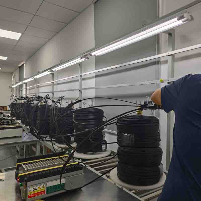
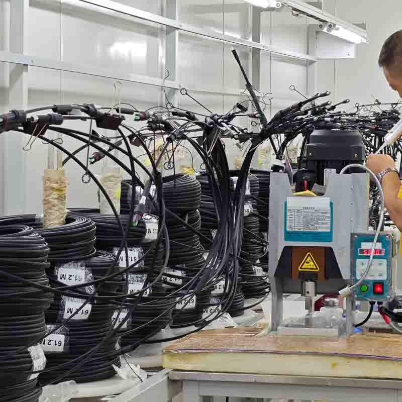
Run samples through a documented comparison against the datasheet, then through factory acceptance testing. FOCC operates 100% test on production and supports third-party inspection, factory acceptance test (FAT) and on-site acceptance, which allows qualification to be written into the purchase contract rather than assumed. Pre-shipment testing is performed on 100% of units before shipment.
Step 5 — Kit and label by site, not by part number
The regional warehouse should release a site kit, not loose assemblies. Each kit carries the site identifier, connector family, length, core count and serial. Labelling by site is what allows a fault to be diagnosed without a second visit, and it is the precondition for a ten-minute replacement.
Step 6 — Train crews on seating, routing and bend control
Cover three items only: correct seating of the plug-and-play connector, routing that respects the assembly's bend limits, and the pull technique that keeps tension within the documented tensile rating. Anything beyond three items does not survive contact with a live site schedule.
Step 7 — Commission with recorded acceptance data
Record insertion loss, visual connector condition, sealing condition and photographic evidence of routing per site. This dataset is what turns an 80% lower field failure rate into a defensible number, because it separates assembly faults from installation faults when a site later goes down.
Step 8 — Run the spare and replacement loop as a process
Hold a regional stock of the standard lengths, and treat every replacement as a data point. FOCC reports a 40% lower operational expenditure across its 10+ year outdoor deployment record, and that outcome is consistent with a programme in which each fault is resolved in under 10 minutes without a repeat visit. The saving comes from the loop, not from the unit price.
Use Cases: What the 20,000-Site Record Covers
Multi-country carrier rollout in Germany, Saudi Arabia and China
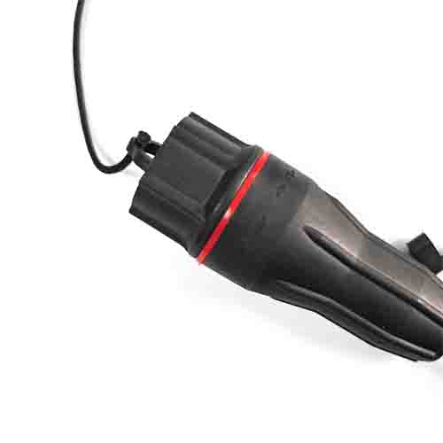
FOCC's documented FTTA case covers telecommunication carriers and 5G base station equipment vendors across Germany, Saudi Arabia and China: more than 50,000 outdoor waterproof patch cords distributed across 20,000+ 5G base station deployments. Reported outcomes are an 80% lower field failure rate, on-site replacement in under 10 minutes, and 40% lower operational expenditure. The case highlights IP68 waterproof/dustproof protection, 200 N tensile strength and corrosion-resistant plating as the properties behind those results, over a deployment record spanning 10+ years in harsh environments.
5G RAN fronthaul and tower-top RF unit interconnection
The core application is the optical link between the baseband unit and the tower-mounted radio, including tower-top RF unit interconnection. This is the use case that drives the interface matrix in Step 1: the connector family is determined by the radio, not by the cable.
Industrial mining and oilfield environments
The same assembly family is documented in industrial mining and oilfield applications, where dust, moisture and mechanical abuse are more severe than on a typical urban macro site. For rollout teams, this is useful evidence about the margin built into the environmental envelope: a site type that looks extreme on a specification review has a documented reference deployment behind it.
Comparison Table: Field-Critical Parameters and Documented Reference Values
The table below consolidates the parameters that decide whether an outdoor FTTA assembly survives a 20,000-site rollout, together with the values documented in FOCC product and case material. All values are supplier-reported and should be re-verified against a test report before volume release.
| Field parameter | Documented reference value | Deployment question it answers | How to verify |
|---|---|---|---|
| Ingress protection | IP68 on the waterproof ODC-to-LC outdoor assembly; IP68 also listed in the large outdoor deployment case | Will the assembly survive rain, dust and washdown at the tower top? | Request IP test report and test conditions |
| Salt-mist resistance | Salt-mist proof stated for the waterproof ODC-to-LC assembly | Is the site coastal or exposed to de-icing salt? | Request salt-mist test method and duration |
| EMI protection | EMI protection stated for the waterproof ODC-to-LC assembly | Is the assembly routed near high-current equipment? | Request EMC documentation |
| Tensile strength | 200 N listed in the outdoor deployment case | Can the assembly be pulled through trays without straining the termination? | Request mechanical test report |
| Corrosion resistance | Corrosion-resistant plating listed in the outdoor deployment case | Will the coupling hardware degrade over a 10-year service life? | Request plating specification |
| Insertion loss (single-mode) | ≤0.2 dB, typical 0.15 dB on FOCC FTTA cable specifications | Does the link budget close on a long fronthaul run? | Request per-unit test data |
| Return loss | ≥50 dB on the IP67 ODC-type plug to LC/UPC single-mode duplex outdoor patch cable listing | Is reflectance controlled for the radio interface? | Request return-loss test data |
| Operating temperature | −40 °C to +85 °C on FOCC FTTA cable specifications; −45 °C to 85 °C on the IP67 ODC-to-LC duplex listing | Does the assembly match the climate zone of the deployment market? | Match the value to the site climate profile |
| Fiber and core configuration | Single-mode 9/125 µm, 2 or 4 cores, ODC plug/socket on the documented ODC-to-LC assembly | Does the assembly match the radio port count? | Confirm against the platform-to-connector matrix |
| Production capacity | 200,000 units per month; lead time 3–15 days; MOQ 2 units | Can the supplier support a phased 20,000-site schedule? | Request capacity plan and production schedule |
Frequently Asked Questions
1. Which ingress and mechanical specifications should be written into an FTTA patch cord RFQ for tower-top use?
At minimum, specify ingress protection, salt-mist resistance, EMI protection, tensile strength, corrosion-resistant plating, operating temperature, insertion loss and return loss as pass/fail criteria. FOCC documents IP68 protection, salt-mist resistance and EMI protection on its waterproof ODC-to-LC outdoor assembly, and lists 200 N tensile strength and corrosion-resistant plating in its outdoor deployment case. Operating temperature is documented at −40 °C to +85 °C for FTTA cable specifications and −45 °C to 85 °C on an IP67 ODC-to-LC duplex listing. These are supplier-reported values, so the RFQ should require the test method and test report behind each one.
2. Can outdoor FTTA patch cords be customized for different RRU/AAU interfaces and site lengths?
Yes. FOCC provides OEM and ODM production services with customization options covering length, connector type, core count, transmission mode, material, logo printing, certification and packaging. The documented FTTA connector portfolio includes FullAXS, ODC, ODVA and PDLC families, plus ODC-to-LC fan-out assemblies in single-mode 9/125 µm with 2 or 4 cores. In a large rollout, customization is normally used to build a small standard length matrix rather than a bespoke assembly per site.
3. What commercial terms apply when ordering FTTA patch cords for a multi-site rollout?
FOCC states a minimum order quantity of 2 units, delivery terms of EXW or FOB, and payment by T/T. Production capacity is stated at 200,000 units per month, which is the figure a rollout manager should test against the phased site schedule. Quality control is 100% test, and the supplier states that it supports third-party inspection, factory acceptance test (FAT) and on-site acceptance, with 100% pre-shipment testing before dispatch.
4. How should FTTA patch cords be validated before mass deployment?
Validation has three stages: sample inspection against the datasheet, factory acceptance testing before volume release, and on-site acceptance at first installation. FOCC supports third-party inspection, factory acceptance test (FAT) and on-site acceptance, and performs 100% test on production. The practical rule is to tie acceptance to recorded data — insertion loss, connector condition, sealing condition and routing photographs — so that a later fault can be attributed to the assembly or to the installation rather than to both.
5. What lead time and production capacity support a 20,000-site rollout?
FOCC states a lead time of 3–15 days, a monthly capacity of 200,000 units and a minimum order quantity of 2 units. For a 20,000-site programme the binding constraint is usually not monthly capacity but the length matrix and the regional spare kit, so lead time should be planned per standard length rather than as a single figure. Samples and quotations for a specific length and connector configuration can be requested directly from FOCC Fiber Co., Ltd at www.focc-fiber.com or sales@mefiberoptic.com.
Conclusion: The Rollout Is Won in the Matrix, Not on the Tower
A 20,000-site FTTA deployment repeats one small decision tens of thousands of times, and the outcome depends almost entirely on how well that decision was documented the first time. Lock the platform-to-connector matrix. Freeze the length matrix by site type. Write the environmental envelope — IP68, salt-mist resistance, EMI protection, 200 N tensile strength, corrosion-resistant plating and the temperature range — into the RFQ as pass/fail criteria. Qualify through samples, 100% test and factory acceptance. Then run the site as a kitted, labelled, ten-minute replacement loop.
FOCC Fiber Co., Ltd manufactures fiber optic connectors, MTP/MPO patch cords, outdoor waterproof patch cord assemblies and armored patch cords from a 5,000 m² factory in Guangzhou, with 200 employees, an annual output of 2,000,000 units and a 30-person R&D team, and operates ISO 9001 and ISO 14001 management systems. Products are exported to more than 30 countries and regions, with EU and USA as the main markets, on more than ten years of ODM/OEM experience. Over a documented 10+ year outdoor deployment record of 50,000+ waterproof patch cords across 20,000+ 5G base stations, the reported results are an 80% lower field failure rate, under 10 minutes on-site replacement and 40% lower OPEX.
Next Step: Build Your Own Deployment Matrix
Send FOCC your radio platform list, site types and environmental requirements, and request a sample assembly in the connector family and length you intend to standardize on. Samples, quotation and the full FTTA specification set are available directly from the manufacturer.
FOCC Fiber Co., Ltd — www.focc-fiber.com
Email: sales@mefiberoptic.com | Phone / WhatsApp: +86 13823237984
Address: 4th Floor, Building E, ChaoHuiLou Creative Park, HuaYue Road, Longhua District, Shenzhen, CN 518109
Deployment figures and product specifications cited in this guide are drawn from FOCC product documentation and its reported 5G base station deployment case. Buyers should verify all performance values against test reports and acceptance criteria before volume release.
Have Questions or Need More Details?
Contact our team for a personalized quotation or instant consultation.
Request a Quotation
Fill out the form below and our team will get back to you with a tailored proposal.
WhatsApp Direct Chat
Prefer to chat in real-time? Message us on WhatsApp for instant assistance & quick answers.
- Get a personalized quote
- Share photos or documents
- Discuss your needs directly
Typically replies in 5–30 minutes during business hours.