
Solving 400G Spine-Leaf Bottlenecks: MPO/MTP Patch Cords
A 400G spine-leaf migration is usually approved on switching capacity and optics, then loses time in the aisle. Fibre counts rise, rack space does not, and the optical loss budget begins to drift once hundreds of multi-fibre connectors are mated during commissioning. MPO/MTP patch cords are the component that most directly removes that constraint — provided they are specified, tested and staged correctly. This article sets out the bottleneck, the specification list, the deployment sequence and the reported outcome of a 400G cloud deployment built on MPO-24 assemblies.

Why 400G Spine-Leaf Fabrics Expose the Physical Layer
A spine-leaf fabric is defined by full-mesh uplinks: each leaf connects to each spine, so the physical link count grows with both switch count and port speed. Raising port speed to 400G concentrates more capacity into fewer, denser connectors. That is efficient at the switch faceplate and demanding everywhere else in the path — cable management, panel space, polarity discipline and the optical loss budget.
Bottleneck 1 — Insertion loss drift across multi-mated links
Every mated connector pair consumes part of the link budget. In a dense fabric a single leaf-to-spine path can pass through a transceiver port, a trunk assembly, a panel module, a jumper and a second panel before reaching the far end. Multi-fibre connectors pack 12 to 48 fibres into one ferrule; if endfaces are contaminated during high-volume mating, or guide-pin engagement is uneven, loss rises unevenly across the channels of that ferrule. The effect appears as margin erosion months after commissioning rather than as an obvious day-one failure, which is why it is often diagnosed late.
Bottleneck 2 — Channel variation, polarity and crosstalk concerns
Parallel optics carry several lanes inside one connector, so the link behaves according to the worst fibre in the ferrule, not the average. Two issues dominate in practice: channel-to-channel variation caused by endface geometry and alignment differences, and polarity errors introduced when straight, rolled or A/B/C wiring methods are mixed across a project. Engineers often describe the resulting interference as crosstalk; in the optical layer the effect is better understood as unequal channel performance plus mapping mistakes. It is removed by a single polarity scheme and per-channel test data, not by shielding.
Bottleneck 3 — Rack space and cable congestion
Traditional LC/SC patching dedicates one connector and one cable to each duplex link. At 400G densities the resulting bundle volume fills vertical managers and restricts airflow in the very cabinets that need it most. Pre-terminated multi-fibre assemblies consolidate many links into one jacketed cable, which is why density projects measure the benefit in ports per rack unit rather than in cable count.
Industry Background: Standard Interfaces Under Rising Density
Density demand is being pushed by AI and cloud cluster build-outs. Global Market Insights projects the data centre cabling market at USD 16.6 billion in 2026 with AI clusters identified as a demand driver, and Market Growth Reports estimates the global MPO fibre optic connector market at USD 1.24 billion in 2026. Both are third-party projections published in the second half of 2026 on a 2025 base year, and both lead to the same procurement consequence: density components are now a planned budget line, not an accessory.
Interoperability rests on published standards. MPO connectors are defined by IEC 61754-7 and, in the North American context, by TIA-604-5 (FOCIS 5). GR-326 is the widely referenced reliability and performance specification for single-mode fibre optic connectors and jumper assemblies, covering endface geometry, loss and mechanical endurance. Where an assembly must work with equipment from more than one vendor, naming these standards in the RFQ is the cheapest way to avoid as-built incompatibility.
Naming causes avoidable confusion. MPO is the interface; MTP is a US Conec trademark for a specific, enhanced implementation of that interface. In procurement documents the safe convention is to state the standard, the fibre count, the polish, the connector gender and the loss grade — and to treat MPO and MTP as interchangeable only once both parties have confirmed the same ferrule and guide-pin configuration.
The Fix: How MPO/MTP Patch Cords Relieve the Bottleneck
The relief comes from three mechanisms working together. Consolidation reduces the number of physical connectors in a path, which reduces cumulative loss and the number of cleaning and mating operations. Pre-termination moves polishing and testing from a live cabinet into a controlled factory process. And a modular architecture — trunk plus panel module plus breakout — lets a fabric be re-patched at the panel instead of re-cabled at the switch.
Configurations to cover 400G spine-leaf links
Core count should follow the transceiver interface and the cabling layer, not the vendor's default. Twelve, sixteen, twenty-four and forty-eight fibre assemblies each have a natural place, and mixing them across a project without a documented mapping is the most common root cause of polarity errors. For transmission mode, OS2 single-mode serves long-reach and inter-building runs, while OM3, OM4 and OM5 multimode cover short-reach within-hall spine-leaf links.
Performance specifications to write into the RFQ
| Parameter | Specification to request | Why it matters in a 400G fabric |
|---|---|---|
| Connector reliability | GR-326 compliance | Gives a common basis for endface geometry, loss and mechanical endurance |
| Interoperability | IEC 61754-7 / TIA-604-5 (FOCIS 5) | Reduces risk of as-built incompatibility between vendors |
| Insertion loss grade | Elite, ≤0.35 dB maximum | Consumes less link budget per mated pair across a multi-connector path |
| Return loss | APC ≥60 dB | Controls reflection in single-mode APC assemblies |
| Fibre type | OS2 / OM3 / OM4 / OM5 | Matches reach and modal bandwidth to the optics in use |
| Jacket | LSZH | Low smoke and limited halogen emission in occupied or return-air spaces |
| Verification | 100% factory tested | Provides per-assembly evidence at handover rather than a sample report |
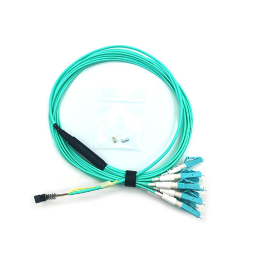
Assembly formats that map to a spine-leaf topology
- MPO trunk optical cable — carries the high-fibre-count run between spine and leaf rows or between MDA and HDA areas, replacing dozens of duplex cords.
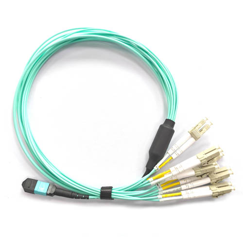
- MPO to LC breakout patch cord — splits a multi-fibre trunk into individual LC duplex ports at the equipment side, which is how mixed-speed server rows stay serviceable.
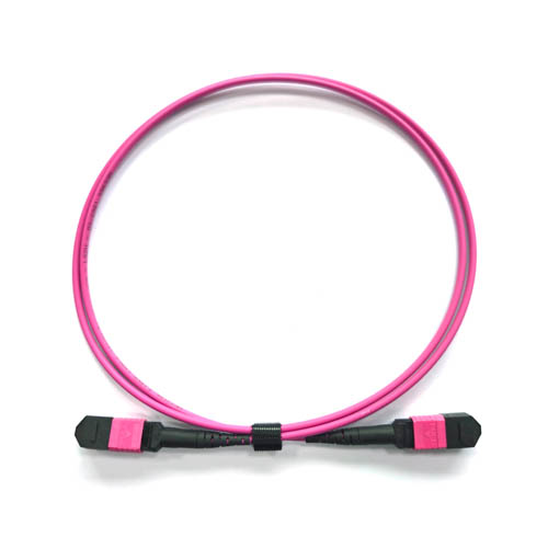
- 12-fibre and 24-fibre MPO patch cords — the working jumpers between transceiver ports, panel modules and trunks.
- MPO fibre optic panel and distribution frame modules — the cross-connect point that allows re-patching without touching switch cabling.
- MPO test patch cords — reference and validation cords for the staging lab, kept separate from production stock to protect endface condition.
Step-by-Step: Specifying and Deploying MPO/MTP Patch Cords
- Count ports and mated pairs before choosing assemblies. Draw the actual path from transceiver to transceiver for one leaf-spine pair and count every mated connector pair. The count determines whether an Elite grade is optional or mandatory in the loss budget.
- Set the loss budget and fix the grade. Allocate loss across trunks, panel modules and jumpers, then specify a maximum insertion loss per mated pair — Elite, ≤0.35 dB — and return loss of ≥60 dB for APC single-mode assemblies. A budget written after the order is placed is not a budget.
- Lock fibre count, polarity and gender in one document. Record core count (12/16/24/48), the polarity method used across the project, and male or female connector gender with guide-pin position. Every subsequent RFQ, label and as-built drawing should reference this single sheet.
- Define the physical build. Specify length tolerance, LSZH jacket, breakout leg length and count, bend-radius allowance, and labelling convention per cabinet and per port. Physical build errors are discovered at installation, when the schedule has the least slack.
- Require 100% test data, not a sample report. Ask for per-assembly insertion loss and return loss results, endface inspection criteria and a certificate of conformity against GR-326 and the agreed standard set. Batch-level sampling cannot prove the condition of the one assembly that lands in a critical uplink.
- Pre-terminate and stage by cabinet. Kit assemblies per cabinet in installation order, with the panel modules and breakout cords in the same package. Pre-terminated trunks and pre-kitted cabinets are the mechanism behind the deployment-speed gains reported in the case below.
Use Cases
400G spine-leaf interconnection in a cloud data centre
A cloud service provider operating across CN, SG and US sites standardised on MPO-24 patch cords for 400G spine-leaf interconnection and server-to-switch high-density cabling. The project used 12,000+ MPO-24 patch cords across 300+ cabinets, with precision active alignment and low insertion loss below 0.35 dB, and every assembly factory tested. Reported results were 60% faster deployment, 4x higher port density, 99.999% uptime and 30% lower total cost of ownership over a service period of 5+ years against a 10-year design life.
MPO-to-LC breakout for mixed-speed server rows
Where a 400G leaf faces server rows that still terminate on LC duplex ports, a trunk from the leaf row feeds a panel module, and MPO-to-LC breakout cords deliver individual duplex services. The fabric can then be re-patched at the panel when a server row is upgraded, without re-pulling the trunk.
Cross-connect modules between MDA and HDA
In a three-tier physical layout, MPO fibre distribution frame modules placed between the main and horizontal distribution areas convert long trunk runs into short, replaceable jumpers. Port-level changes stop requiring work inside the spine cabinet, which protects both uptime and airflow.
Staging lab and acceptance testing
Before a pod goes live, MPO test patch cords and a reference cord set allow loss and polarity verification against the as-built drawing. Keeping test cords out of production stock preserves their endface condition and keeps measurement repeatable.
Comparing MPO/MTP Configurations for 400G Links
The table below compares the four common core counts on the criteria that decide where each belongs in a spine-leaf build. It compares configuration roles, not brands.
| Configuration | Fibre count | Typical role in a 400G fabric | What to confirm when ordering |
|---|---|---|---|
| 12-fibre MPO / MTP | 12 | Working jumpers, panel-to-panel feeds, base for MPO-to-LC fan-out | Polarity method, connector gender, guide-pin position, loss grade |
| 16-fibre MPO / MTP | 16 | Links that terminate parallel 400G interfaces on a 16-fibre ferrule | Ferrule and interface compatibility with the installed transceiver, channel mapping |
| 24-fibre MPO / MTP | 24 | High-density trunk between spine and leaf rows or MDA and EDA areas | Fibre mapping to the panel, breakout leg count, trunk length tolerance |
| 48-fibre MPO / MTP | 48 | Backbone and cross-connect runs where rack space is the binding constraint | Cable diameter and bend radius, panel port count, per-assembly test documentation |
Supplier Snapshot: FOCC Fiber Co.,Ltd
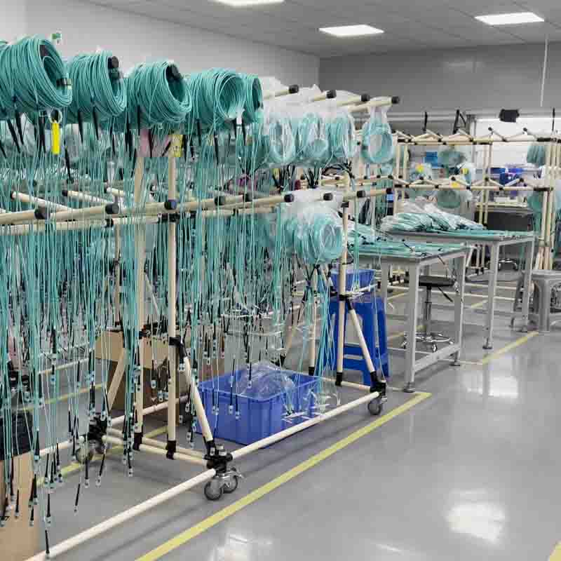
FOCC Fiber Co.,Ltd is a Shenzhen-based supplier of fibre optic connectors, MTP/MPO fibre optic patch cords, and outdoor waterproof and armoured patch cord assemblies for new-generation data centre and FTTA solutions. The company was founded in 2014, operates a 5,000 m² factory in Guangzhou, reports approximately 200 employees and a 30-person R&D team, and states annual output of 2,000,000 units with products exported to the EU and USA. FOCC Fiber states that it implements ISO 9001 and ISO 14001 management systems and lists Prysmian, Siemens, Coherent, Fujikura and NTT among its partner clients.
| Supply item | FOCC Fiber Co.,Ltd detail |
|---|---|
| Production mode | OEM / ODM |
| Customisation | Length, connector type, core count, transmission mode, material, logo printing, certification, packaging |
| Monthly capacity | 200,000 units |
| Lead time | 3–15 days |
| MOQ | 2 units |
| Quality control | 100% test |
| Export markets | EU / Middle East / USA |
| After-sales | Remote support |
Frequently Asked Questions
Which standards and performance grades should an MPO/MTP patch cord meet for a 400G spine-leaf link?
A compliant specification names four things. GR-326 for connector reliability and endface geometry; IEC 61754-7 and TIA-604-5 (FOCIS 5) for intermateability; an Elite insertion loss grade of ≤0.35 dB maximum so each mated pair consumes less of the link budget; and, for single-mode APC assemblies, a return loss of ≥60 dB. Add an LSZH jacket for indoor cabinets and 100% factory testing so each assembly, rather than a batch sample, carries measured loss data. Stating all four in the RFQ prevents a supplier from quoting to a lower grade by default.
Can one supplier cover trunks, breakouts and panel modules for a single spine-leaf pod?
FOCC Fiber Co.,Ltd supplies MPO/MTP patch cords in 12, 16, 24 and 48 fibre configurations across OS2, OM3, OM4 and OM5, together with MPO to LC breakout cords, MPO fibre optic panels and distribution frame modules, and MPO test patch cords. The company operates in OEM/ODM mode with customisation of length, connector type, core count, transmission mode, material, logo printing, certification and packaging, at a stated monthly capacity of 200,000 units with 100% testing. Sourcing the trunk, the breakout and the panel from one production line removes the interface mismatch that appears when three vendors interpret a polarity drawing differently.
What drives the cost of MPO/MTP patch cords in a 400G build?
Cost is driven by core count, connector grade, polish, assembly length, breakout leg count and the level of test documentation — not by the connector shell alone. Two levers matter at evaluation stage. First, moving to an Elite grade of ≤0.35 dB buys loss margin that would otherwise be spent on additional hardware. Second, architecture decides total cost more than unit price: in the cloud deployment cited above, 12,000+ MPO-24 patch cords across 300+ cabinets were reported to deliver 30% lower total cost of ownership alongside 4x higher port density. FOCC Fiber quotes from an MOQ of 2 units, so a single-cabinet evaluation does not require a volume commitment.
How should a buyer validate a sample before releasing a 400G order?
Order a sample at the minimum order quantity — 2 units at FOCC Fiber — and test it as a system rather than as a loose cord. Inspect endfaces against the agreed criteria, confirm the measured insertion loss is within the ≤0.35 dB Elite limit, verify return loss of ≥60 dB on APC single-mode samples, and check polarity and connector gender against the project sheet. Then install the sample in the actual panel module and transceiver you will deploy, because most compatibility issues appear at the panel interface, not on the bench. Request the per-assembly test record with the sample, so the document format is agreed before volume production starts.
What lead time and capacity should be planned for a cabinet-level rollout?
FOCC Fiber states a lead time of 3–15 days and a monthly capacity of 200,000 units, with OEM/ODM customisation and remote after-sales support. For a multi-cabinet rollout, plan around kitting rather than around individual part numbers: sequencing assemblies by cabinet, with panel modules and breakout cords in the same shipment, is what allows installation crews to work cabinet by cabinet. Share the cabinet count, core-count mix and required delivery windows with the supplier early, because 3–15 days applies to production and not necessarily to a full pod kit. To start a sample or quotation request, send the bill of materials to sales@mefiberoptic.com or WhatsApp +86 13823237984.
Conclusion
The 400G spine-leaf bottleneck is rarely a single dramatic failure. It is the accumulation of loss drift across multi-mated connectors, uneven channel performance and polarity mistakes in dense ferrules, and cabinets that run out of cable space before they run out of ports. MPO/MTP patch cords address all three at once, but only when the specification is explicit: GR-326 and IEC 61754-7 / TIA-604-5 as the compliance basis, Elite ≤0.35 dB and APC ≥60 dB as the performance floor, OS2/OM3/OM4/OM5 matched to reach, 12/16/24/48 cores matched to the cabling layer, LSZH jacket for indoor installations, and 100% factory testing as a delivery condition rather than an option.
The evidence from the 400G cloud deployment — 12,000+ MPO-24 patch cords across 300+ cabinets, 60% faster deployment, 4x higher port density, 99.999% uptime and 30% lower total cost of ownership — did not come from a better connector alone. It came from a pre-terminated, pre-tested, pre-kitted architecture in which the patch cord, the panel module and the breakout were designed as one system.
Request a sample or quotation
FOCC Fiber Co.,Ltd — MPO/MTP patch cords, trunk cables, MPO to LC breakout cords and MPO fibre optic panels in 12/16/24/48 fibre configurations, OS2/OM3/OM4/OM5, Elite ≤0.35 dB, LSZH, 100% factory tested. MOQ from 2 units, lead time 3–15 days.
Email: sales@mefiberoptic.com · WhatsApp: +86 13823237984 · Web: www.focc-fiber.com
Address: 4th Floor, Building E, ChaoHuiLou Creative Park, HuaYue Road, Longhua District, Shenzhen, CN 518109

Have Questions or Need More Details?
Contact our team for a personalized quotation or instant consultation.
Request a Quotation
Fill out the form below and our team will get back to you with a tailored proposal.
WhatsApp Direct Chat
Prefer to chat in real-time? Message us on WhatsApp for instant assistance & quick answers.
- Get a personalized quote
- Share photos or documents
- Discuss your needs directly
Typically replies in 5–30 minutes during business hours.