MPO-12 vs. MPO-24: Which MPO/MTP Core Count Wins for 400G Data Centers?
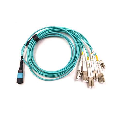
At 400G, the core count of an MPO/MTP patch cord is not a brand preference. It is a cabling architecture decision that fixes how many connectors, panel ports, trunk runs and labor hours a rack will consume. MPO-12 keeps a single 8-fiber 400G channel inside one 12-fiber connector and leaves four fibers in reserve. MPO-24 packages two 12-fiber groups in one connector body, so one trunk can do the work of two.
The short answer for most 400G spine-leaf designs: MPO-12 belongs at the port edge, where optical transceivers connect one channel at a time, and MPO-24 belongs at the trunk and panel layer, where fewer connectors and fewer cable runs translate directly into rack space and installation time. High-density builds usually run both, with a 24-core trunk feeding 12-core or MPO-to-LC breakouts at the equipment end.
This comparison is written for data center engineers and network planners choosing a core count for a 400G build or upgrade. It is grounded in a verified FOCC Fiber Co.,Ltd project in which more than 12,000 MPO-24 patch cords were installed across 300+ cabinets, delivering 60% faster deployment, 4x higher port density, 99.999% uptime and 30% lower TCO, and in the specification floor both core counts share: 12, 16, 24 or 48 cores, Elite-grade insertion loss ≤0.35 dB, return loss ≥60 dB for APC, and customizable lengths from 1 to 100 meters.
The Problem: One Connector Family, Two Different Cost Centers
A 400G data center contains two cabling layers that are paid for in different currencies. The port-side layer is paid for in flexibility: each 400G port consumes one 8-fiber channel, and the connector at that port must match that granularity so a single link can be moved, tested or replaced without disturbing its neighbors. The trunk-and-panel layer is paid for in space and labor: connector count, trunk count, cable management volume and termination time all scale with the number of connector ends, not with the number of fibers.
Choosing one core count for both layers forces a compromise. Standardizing on 12-core everywhere keeps the port edge simple but multiplies trunk runs and panel ports. Standardizing on 24-core everywhere halves the hardware count but introduces a de-interleaving step wherever a single 400G port needs to be addressed. The decision is therefore not which connector is better, but which layer a given core count should own.
Seven variables drive that assignment, and each one moves the answer in a predictable direction:
- Ports per rack and fiber count per port.
- Panel units and rack space available at the leaf and spine.
- Cable tray fill, bend radius and cable management volume.
- Connector terminations and test points per 48 fibers.
- Spare-fiber ratio and re-arrangement headroom.
- Migration path to the next speed step.
- Polarity and group-mapping discipline in the cabling plan.
Because these variables act per layer rather than per project, the evaluation method later in this article scores 12-core and 24-core assemblies per cabling layer instead of declaring one global winner.
Industry Background: Why MPO/MTP Sets the 400G Baseline
MPO connectors are defined by international standards IEC 61754-7 and TIA-604-5 (FOCIS 5), which ensure intermateability between connectors from different manufacturers. That property matters more at 400G than at any earlier speed, because a multi-vendor cabling plan depends on any compliant MPO-12 mating with a compliant 24-core fan-out downstream. MTP is a registered trademark of US Conec denoting an enhanced MPO version with a floating ferrule and elliptical guide pins for improved optical performance. In procurement documents the two terms are often used interchangeably, but the trademark belongs to one supplier and the interface standard belongs to the industry.
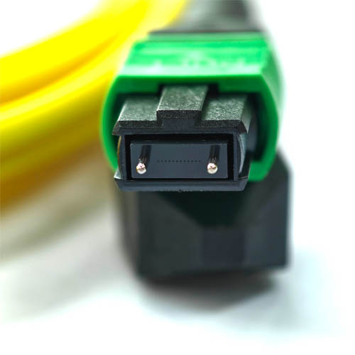
Adoption is no longer an early-adopter question. Multimode MPO connectors held more than 88% of the product segment in 2024, driven by short-range data center interconnects, and hyperscale data centers integrated MPO connectors in more than 70% of their facilities globally in 2024 to support parallel optics and high-density cabling. The 12-versus-24 question is therefore an optimization question inside an established technology, not a technology selection question.
FOCC Fiber Co.,Ltd is a Shenzhen-based manufacturer of high-performance, high-density fiber optic connectors, MTP/MPO fiber optic patch cords, outdoor waterproof patch cord assemblies and armored patch cords for data center and FTTA solutions. Founded in 2014, the company operates a 5,000 square meter manufacturing facility in Guangzhou with approximately 200 employees, a 30-engineer R&D team and an annual production capacity of about 2,000,000 units. Its products are exported to the EU and USA, and export accounts for 100% of sales.
How 12-Core and 24-Core Assemblies Differ Inside a 400G Rack
MPO-12: one 8-fiber channel, four fibers in reserve
A 12-fiber MPO patch cord carries a single 8-fiber 400G channel plus four reserve fibers. In practice this makes MPO-12 the natural termination at the transceiver: one connector maps to one port, so a link can be added, removed or re-tested without touching the rest of the panel. The reserve fibers provide a small, well-understood amount of re-arrangement headroom and keep the assembly organized in a fixed 12-fiber group.
For a 48-fiber bundle, an all-MPO-12 design consumes four connectors and four trunk runs at each end. Every additional connector end is one more termination, one more test point and one more potential polarity error, which is why port-level simplicity still has a measurable operational cost at scale.
MPO-24: two 12-fiber groups in one connector
A 24-fiber connector carries two 12-fiber groups, which means two 8-fiber 400G channels with four reserve fibers per group. In a 400G spine-leaf build this is the trunk-layer advantage: the same 48 fibers that require four MPO-12 connectors at each end require only two MPO-24 connectors, halving connector ends, trunk runs, panel ports and the associated termination and test labor.
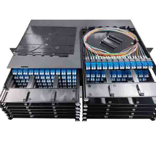
The cost of that density is a mapping step. Where a single 400G port must be addressed from a 24-core trunk, the cabling plan needs an explicit de-interleaving point, typically an MPO-to-MPO module or an MPO-to-LC breakout, so that group A and group B never get crossed between the spine and the leaf. Documenting that map once, and repeating it in the purchase order, is the difference between a dense build and a dense build that fails acceptance testing.
Optical performance is set by grade, not by core count
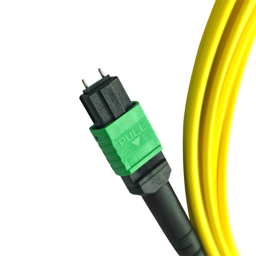
Insertion loss and return loss do not change when fiber count changes. The MPO/MTP fiber optic patch cord family supports core counts of 12, 16, 24 and 48, optical fiber types OS2, OM3, OM4 and OM5, Elite-grade insertion loss of ≤0.35 dB (≤0.5 dB for standard grade), return loss of ≥60 dB for APC and ≥50 dB for UPC, an operating temperature range of -20°C to +70°C, LSZH jacket, customizable lengths from 1 to 100 meters and Telcordia GR-326 compliance. Construction uses a zirconia ceramic ferrule, a PBT/PEI connector housing and Kevlar aramid yarn reinforcement.
Procurement implication: a 24-core cord is not inherently better or worse optically than a 12-core cord. Once the grade is fixed (Elite, APC, OS2 or OM4), the decision returns to density, labor and space.
Where the two core counts meet
Most 400G builds are hybrids. A typical arrangement runs a 24-core trunk between spine and leaf panels and breaks out to 12-core cords or MPO-to-LC fan-outs at the server and switch ports, keeping single-port granularity where operations need it and density where space is scarce. The same logic extends upward: a 48-core trunk is available where even 24-core runs would crowd the tray, and because the connector interface stays constant, all three counts can coexist on one panel layer. Model designations such as MPO-12-OS2-APC, MTP-24-OM4-UPC and MTP-48-OM3-UPC show how core count, fiber type and polish combine in a single part number.
Step-by-Step: Choosing the Core Count for a 400G Build
Step 1 — Count fibers per port and per rack
Start from the optical interface, not from the catalog. If each 400G port consumes one 8-fiber channel, a rack with N active ports needs 8N fibers plus whatever spare ratio the operations team accepts. That single number determines whether a 12-core or 24-core assembly is the natural building block, and it prevents over-ordering by a comfortable margin.
Step 2 — Assign connector granularity by layer
Port-side terminations should match the port count; trunk-side terminations should match the fiber total. Writing this rule into the cabling plan prevents the two most common failures in 400G projects: 24-core cords at the transceiver, which force de-interleaving at every port, and 12-core trunks between panels, which double the trunk count for no operational benefit.
Step 3 — Fix polarity and group mapping before ordering
A 24-core assembly contains two 12-fiber groups and a defined key orientation. The polarity scheme, the group order (A before B or B before A) and the breakout assignment must be documented and repeated in the purchase order. A mapping error discovered after installation costs far more than the cords themselves, and it is the single most common reason a dense design underperforms its paper specification.
Step 4 — Set the loss budget and the grade
Convert the optical budget into a per-connector allowance. With Elite-grade insertion loss ≤0.35 dB and return loss ≥60 dB for APC, a design can tolerate more mated pairs across the same channel than with standard ≤0.5 dB terminations, which is exactly what a 24-core trunk with two transition points needs. For single-mode runs, APC polish with ≥60 dB return loss should be treated as the baseline rather than an upgrade.
Step 5 — Validate with one cabinet, then scale
Build one cabinet with the planned mix of 24-core trunks, 12-core cords and breakouts, then measure insertion loss and return loss, verify polarity against the map and confirm that labeling survives a real re-arrangement. Only then release the full bill of materials. Because lengths are customizable from 1 to 100 meters, the pilot also validates the length schedule before volume ordering begins.
Verified Project Data: What 12,000+ MPO-24 Patch Cords Across 300+ Cabinets Showed
The 24-core argument is usually made theoretically. In a FOCC Fiber Co.,Ltd data center deployment, more than 12,000 MPO-24 patch cords were installed across 300+ cabinets in a 400G environment. The measured outcomes were 60% faster deployment, 4x higher port density, 99.999% uptime and 30% lower TCO compared with the layout it replaced.
Read those four numbers as a chain rather than as a list. Fewer connector ends per 48 fibers reduced the number of termination and test points, which is where the 60% deployment speed gain originates. Two 12-fiber groups in one connector, paired with high-density panels, produced the 4x port density improvement in the same rack space. Fewer mated pairs and fewer physical touch points during re-arrangement support the 99.999% uptime figure. And because labor, panel ports and trunk runs dominate the cost of a 400G cabling project, the combined effect appeared as 30% lower TCO.
The limits matter as much as the results. MPO-24 is the wrong answer when ports are added one at a time with no panel layer to absorb de-interleaving, when the operating team has no documented polarity map, or when the installed base is entirely 12-fiber and a mixed trunk standard would create two parallel practices. In those cases MPO-12 remains the lower-risk choice, even at the cost of more connectors and more trunk runs.
Use Cases: Where Each Core Count Earns Its Place
Spine-side aggregation in a leaf-spine fabric
The spine panel is the highest-fiber-count point in the fabric and the least tolerant of space pressure. A 24-core trunk between leaf and spine panels halves the connector and run count for the same fiber total, and it is here that the 4x port density outcome is easiest to reproduce.
Server-to-switch connections at the top of rack
At the server end, links are added, moved and tested individually. A 12-core cord delivers exactly one 8-fiber 400G channel per connector, so a single port can be re-patched without touching its neighbors — the operational behavior most teams expect from a conventional patch panel, retained at multi-fiber density.
MPO-to-LC breakout for mixed and legacy equipment
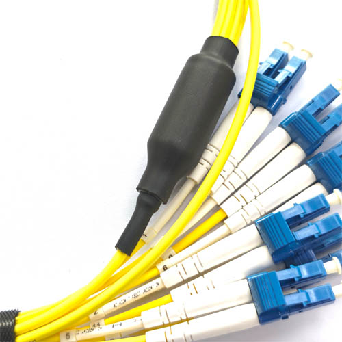
Where 400G ports must reach LC-based equipment, an MPO to LC patch cord or fan-out converts a multi-fiber connector into duplex LC pairs. The same logic lets a 24-core trunk present multiple LC duplex paths while the trunk side stays dense, and lets a 12-core cord present a fixed 8-channel assignment with four spare fibers. This is the transition point where the two core counts cooperate rather than compete.
Single-mode runs across rows and buildings
Longer intra-campus and inter-building runs shift the choice toward OS2 single-mode assemblies with APC polish and return loss ≥60 dB. Single-mode MPO patch cords are available in the same 12, 16, 24 and 48 core counts, so the core-count decision can be made independently of the fiber-type decision.
Staged migration to the next speed step
A 24-core trunk installed for 400G leaves fiber groups available for the next step, while a 12-core installation preserves the same per-port structure and grows one channel at a time. Teams expecting dense, contiguous growth usually prefer the 24-core trunk with breakouts; teams expecting scattered port-level growth usually prefer 12-core throughout and accept the additional trunks.
Comparison Table: MPO-12 vs. MPO-24 for 400G Data Centers
| Criterion | MPO-12 (12-fiber patch cord) | MPO-24 (24-fiber patch cord) |
|---|---|---|
| Fibers per connector | 12 | 24 (family also covers 16 and 48 cores) |
| 8-fiber 400G channels per connector | 1 channel plus 4 reserve fibers | 2 channels, one per 12-fiber group, plus 4 reserve fibers per group |
| Connector ends per 48 fibers | 4 at each end | 2 at each end |
| Typical role in 400G | Transceiver port termination; single-port moves and tests | Spine-leaf trunk; panel-to-panel aggregation |
| Rack space and panel port pressure | Higher | Lower |
| Termination and test labor per 48 fibers | Higher (more connector ends) | Lower (fewer connector ends) |
| De-interleaving step | Not required | Required wherever a single 400G port is addressed |
| Migration headroom | Incremental, per port | Larger contiguous blocks |
| Insertion loss | ≤0.35 dB (Elite) / ≤0.5 dB (standard) | ≤0.35 dB (Elite) / ≤0.5 dB (standard) |
| Return loss | ≥60 dB (APC) / ≥50 dB (UPC) | ≥60 dB (APC) / ≥50 dB (UPC) |
| Fiber types | OS2 / OM3 / OM4 / OM5 | OS2 / OM3 / OM4 / OM5 |
| Length | Customizable, 1–100 m | Customizable, 1–100 m |
| Jacket and compliance | LSZH; Telcordia GR-326 | LSZH; Telcordia GR-326 |
| Best fit | Port-by-port growth, LC breakout endpoints, mixed vendor installs | Dense spine panels, full-cabinet deployments with a planned panel layer |
Channel counts in this table are derived from fiber count and the 8-fiber 400G port design, not from a manufacturer-specific specification. Loss, return loss, fiber type, length, jacket and compliance values are the shared specification of the MPO/MTP fiber optic patch cord family, which supports 12, 16, 24 and 48 core counts.
FAQ: MPO-12 vs. MPO-24 in 400G Deployments
Are MPO-12 and MPO-24 connectors compliant with the same standards?
Yes. MPO connectors are defined by IEC 61754-7 and TIA-604-5 (FOCIS 5), which set the interface dimensions needed for intermateability between manufacturers. Changing the core count from 12 to 24 changes the number of fiber positions in the ferrule, not the connector standard family, so a 24-core trunk terminates and mates within the same standards framework as a 12-core cord. MTP is a registered trademark of US Conec describing an enhanced MPO connector with a floating ferrule and elliptical guide pins.
Can one manufacturer supply both 12-core and 24-core assemblies at Elite grade?
FOCC Fiber Co.,Ltd supplies MPO/MTP fiber optic patch cords in 12, 16, 24 and 48 core counts, in OS2, OM3, OM4 and OM5 fiber types, with Elite-grade insertion loss of ≤0.35 dB, return loss of ≥60 dB for APC, LSZH jackets, customizable lengths from 1 to 100 meters and Telcordia GR-326 compliance. The company operates a 5,000 square meter facility with approximately 200 employees, a 30-engineer R&D team and an annual capacity of about 2,000,000 units.
Does MPO-24 actually lower cost, or only reduce connector count?
It lowers total cost of ownership through connector count, panel ports and installation labor, not through a different unit price for the connector itself. In a FOCC data center project, more than 12,000 MPO-24 patch cords across 300+ cabinets produced 30% lower TCO together with 60% faster deployment and 4x higher port density. The saving assumes a panel layer where 24-to-12 de-interleaving is planned; without that layer, additional transition hardware and rework can absorb the difference.
How can a 12-versus-24 decision be validated before the full rollout?
Build one pilot cabinet using the intended mix of 24-core trunks, 12-core cords and breakouts, then measure insertion loss and return loss and verify the polarity and group map. Test patch cords are used for this validation, and because lengths are customizable from 1 to 100 meters, the pilot also confirms the length schedule before volume ordering begins.
What capacity and lead time should a 400G rollout plan for?
Capacity is the easier half of the question: FOCC operates a 5,000 square meter facility with about 200 employees and an annual production capacity of roughly 2,000,000 units, with a 30-engineer R&D team supporting custom configurations and 100% of output exported to the EU and USA. Lead time is set per project against the confirmed bill of materials, core counts and length schedule, so it is best requested together with the pilot results. To start, share your port count and cabinet plan with the FOCC team at sales@mefiberoptic.com or +86 13823237984, or visit www.focc-fiber.com.

Decide the core count with real measurements, not assumptions
Request an MPO-12 and MPO-24 sample set, a test patch cord for pilot-cabinet validation, or a project-specific quotation based on your cabinet plan and length schedule.
Email sales@mefiberoptic.com | WhatsApp / Tel +86 13823237984 | www.focc-fiber.com
Conclusion
Neither core count wins everywhere. MPO-12 wins at the port edge, where one connector should equal one 400G channel. MPO-24 wins at the trunk and panel layer, where one connector should equal two. The build that performs best at 400G is almost always a deliberate mix: 24-core trunks for density and installation speed, 12-core cords and MPO-to-LC breakouts for operational granularity, held together by a documented polarity map and a fixed Elite-grade loss budget of ≤0.35 dB insertion loss and ≥60 dB return loss for APC.
The verified FOCC project results, more than 12,000 MPO-24 patch cords across 300+ cabinets at 60% faster deployment, 4x higher port density, 99.999% uptime and 30% lower TCO, show what that mix delivers when the trunk layer is designed for it. They also show what it costs when it is not: a dense trunk without a mapped de-interleaving point transfers the saving back to rework. Choose the core count per layer, not per project.
Have Questions or Need More Details?
Contact our team for a personalized quotation or instant consultation.
Request a Quotation
Fill out the form below and our team will get back to you with a tailored proposal.
WhatsApp Direct Chat
Prefer to chat in real-time? Message us on WhatsApp for instant assistance & quick answers.
- Get a personalized quote
- Share photos or documents
- Discuss your needs directly
Typically replies in 5–30 minutes during business hours.