
Top 5 MPO/MTP Patch Cords for 400G Data Center Upgrades in 2026
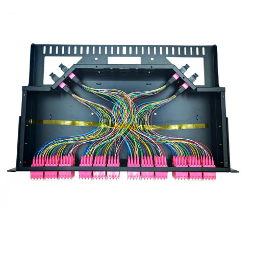
High-density MPO/MTP cabling hardware: 1U 96-144F MTP-LC patch panel from the FOCC Fiber data center portfolio.
If you are locking down the physical layer for a 400G or 800G rollout in 2026, here is the ranked short answer. 16-fiber single-mode MPO-16 patch cords (OS2, APC) rank first for new single-mode parallel links. 12-fiber OS2 cords with 8-fiber mapping rank second where 12-fiber infrastructure is already installed. 24-fiber multimode OM4 cords rank third for short-reach, high-density rows. 12F/24F MPO-to-LC breakout patch cords rank fourth as the migration bridge for existing LC racks. 48-fiber or 24-fiber MPO/MTP trunks terminated into 1U patch panel modules rank fifth for pod-level backbones.
The ranking is not a beauty contest between connector brands. It is built from three inputs: first-party manufacturing and test facts from FOCC Fiber Co., Ltd, verified market and standards data for MPO connectors, and the configuration logic that 400G/800G link budgets impose on fiber count, polish and polarity. Each entry below states what the configuration is, why it holds its rank, and where its limits begin.
The 400G Patch Cord Problem: Density, Alignment and Loss Budget
In a 400G upgrade the bottleneck is no longer the switch. It is the physical layer behind the switch. Traditional single-core LC/SC duplex patch cords scale linearly: every added port adds a cord, a tray position, a labeling task and a human termination point. At 400G port counts, that arithmetic breaks cable management long before it breaks the optics.
Multi-core MPO integration changes the ratio. Compared with traditional single-core LC/SC patch cords, MPO assemblies deliver 8-24x higher port density, 0.2 dB lower insertion loss and 60% faster deployment, while supporting 40G/100G/400G high-speed transmission. The same integration also introduces failure modes that do not exist in duplex cabling: multi-core alignment error, insertion loss drift, and crosstalk at high-speed transmission.
That is the real decision framework behind this list. A 400G buyer is not choosing between "MPO" and "not MPO". The buyer is choosing a fiber count, a polish, a polarity and a performance grade for each link type, then proving that the supplier can hold all four across every assembly shipped.
Industry Background: How the MPO/MTP Market and Standards Look in 2026
MPO connectivity is a mature, standardized layer that is still expanding. Strategic Market Research estimates the global MPO fiber optic connector market at approximately USD 2.1 billion in 2024, projected to reach USD 3.2 billion by 2030. Buyers should also know that Valuates Reports values the same 2024 market at roughly USD 741 million. The gap is a scope difference, not a contradiction: one figure covers the connector, the other covers a narrower reporting boundary than full cable assemblies. Any market number you put in a business case should be checked for scope before it is used.
Three structural facts shape 2026 demand. Asia-Pacific is the largest regional market for MPO connectors, accounting for approximately 42% of global share in 2024, followed by North America. Multimode MPO connectors dominate the product segment with over 88% of market share, driven by short-range data center interconnects. And hyperscale data centers integrated MPO connectors in over 70% of their facilities globally in 2024 to support parallel optics and high-density cabling.
Two terminology points matter when you write a specification. First, MPO connectors are defined by international standards IEC 61754-7 and TIA-604-5 (FOCIS 5), which is what guarantees intermateability across different manufacturers. Second, MTP is a registered trademark of US Conec and refers to an enhanced MPO version featuring a floating ferrule and elliptical guide pins for improved optical performance. At connector level, US Conec held approximately 18% and Senko nearly 15% of the global MPO connector market share in 2024.
How This Top 5 Was Scored
The five configurations were ranked on five criteria, each of which reflects how a 400G/800G upgrade actually succeeds or fails:
- Interface fit — does the fiber count match the module's lane architecture and reach?
- Density gain per rack unit — measured against the single-core LC/SC baseline.
- Deployment speed — how much installation and re-termination labor the configuration removes.
- Insertion loss and alignment control — what the assembly process can hold at 12 to 48 cores.
- Migration flexibility — whether the configuration protects existing cabling investment.
Evidence came from FOCC Fiber's first-party manufacturing and test records (precision polishing, active alignment technology, crosstalk suppression design, 100% insertion loss testing, automated alignment inspection and high-speed signal integrity validation), from the verified market and standards data above, and from deployment patterns in the export markets FOCC serves. FOCC Fiber Co., Ltd manufactures in Shenzhen and Guangzhou, exports 100% of its output to more than 30 countries and regions, and lists its main markets as the EU and USA.
Where a project's tender specifies a low-loss or premium performance grade for insertion loss, that grade definition should be mapped to the buyer's own test protocol and confirmed in writing with the supplier — the grade label alone does not prove assembly performance.
The Top 5 MPO/MTP Patch Cords for 400G Data Center Upgrades
Rank 1 — 16-Fiber MPO-16 Single-Mode Patch Cord (OS2, APC)
MPO Single-Mode Patch CordNew-build 400GAPC polish
This is a pre-terminated 16-fiber MPO/MTP assembly on OS2 single-mode fiber with an angled physical contact (APC) end-face. It ranks first because new single-mode 400G and 800G links are built around parallel lane architectures, and the 16-fiber interface matches those architectures without wasting fiber positions. On a greenfield build there is no legacy constraint, so the correct move is to match the module interface directly rather than compromise.
The assembly-level benefits are the ones already measured across FOCC's multi-core range: 8-24x higher port density than single-core LC/SC cabling, 0.2 dB lower insertion loss, 60% faster deployment, 70% less rack space and 15% lower transmission loss, with reduced cooling energy as a secondary effect.
Limits to plan for: APC end-faces must never be mated with UPC; polarity and mapping must be documented before the first cord is ordered; and 16-fiber cleaning and test tooling has to be in the rack kit, not borrowed later.
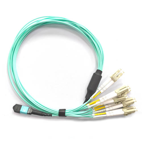
MPO patch cord assembly: multi-core integration replaces multiple duplex cords per port group.
Rank 2 — 12-Fiber MPO Single-Mode Patch Cord with 8-Fiber Mapping (OS2)
MPO to LC Patch CordLegacy 12F reuse8-fiber mapping
This configuration uses the long-established 12-fiber MPO footprint, with 8 of the 12 positions carrying the transmit and receive lanes of an 8-lane 400G single-mode link. It ranks second because it is the lowest-disruption path available to sites that already run 12-fiber MPO trunks, cassettes and panels — the optics are upgraded, but the structured cabling stays in place.
Where 12-fiber infrastructure exists, this configuration inherits the same multi-core advantages over single-core LC/SC patch cords: fewer cords per rack unit, faster deployment, lower insertion loss per link and simplified cable management. It also keeps one polarity scheme across the whole site, which reduces the most common human error in high-density fiber work.
Limits to plan for: four of the twelve fibers are unused when only eight lanes are active, so fiber utilization is lower than a 16-fiber build. On 16-lane module ports, two 12-fiber cords are needed instead of one 16-fiber cord, which adds cord count and cable-management load.
Rank 3 — 24-Fiber MPO Multimode Patch Cord (OM4, OM5 Where Specified)
MPO Multimode Patch CordHigh-Density MPO Patch Cables
This is a 24-fiber multimode assembly for short-reach 400G links inside a data hall, and for breakout arrangements where a single connector feeds multiple 12-fiber or 8-fiber groupings. It ranks third because multimode remains the volume reality of intra-data-center cabling: multimode MPO connectors hold over 88% of the MPO connector market share, driven by short-range interconnect demand.
Twenty-four fibers per connector doubles the fiber count of the classic 12-fiber footprint and therefore raises density at the row level, where the highest concentration of links sits. OM4 is the mainstream baseline; OM5 is specified only where the project's link budget and wideband multimode requirement call for it, and that decision should be confirmed against the project specification rather than assumed.
Limits to plan for: multimode performance is distance-bound, so reach must be fixed before the fiber type is chosen. Polarity and breakout mapping need a documented scheme, and every fan-out orientation should be verified against the patch panel layout at commissioning.
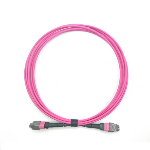
MPO multimode patch cord: the volume configuration for short-reach 400G links inside a data hall.
Rank 4 — MPO-to-LC Breakout (Fan-Out) Patch Cord, 12F/24F to LC Duplex
MPO Breakout Patch CordMigration path12F MT-LC fan out
An MPO/MTP connector on one end and LC duplex fan-out legs on the other. This is the migration bridge, and it ranks fourth because most 400G upgrades happen inside racks that still contain 10G and 25G LC-based servers and leaf switches. A breakout cord connects the new MPO trunk to that existing LC estate without replacing every server interface on day one.
The verified economics work at the trunk layer rather than at the port: compared with traditional single-core LC/SC patch cords, the MPO approach carries 15-20% higher upfront cost but roughly 30% lower total cost of ownership through reduced cable and labor costs, 50% fewer failure points, modular replacement in under 5 minutes and simplified cable management.
Limits to plan for: a fan-out leg is still a single-fiber interface per port, so it does not deliver the full density gain of a native MPO link. Treat it as a transition tool with a documented retirement plan, not as the end state of the cabling design.
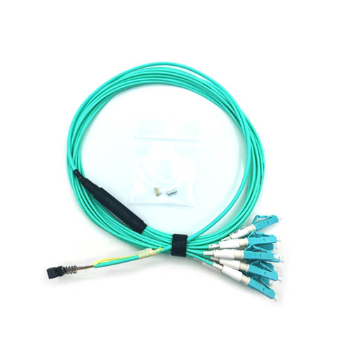
12F MT-LC fan-out patch cord: connects existing LC duplex ports to new MPO/MTP trunk cabling.
Rank 5 — 48-Fiber or 24-Fiber MPO/MTP Trunk with 1U MTP-LC Patch Panel Module
MPO Trunk Optical CableMPO Patch PanelFiber Distribution Frame Module
This is the infrastructure layer: pre-terminated MPO/MTP trunk cable terminated into a 1U 96-144F MTP-LC patch panel and distribution frame module. It ranks fifth not because it is weak, but because it cannot be deployed link by link. It requires accurate port maps, panel layouts and cable lengths first, and that planning cycle is what places it behind the four configuration families above.
Once installed, the effect is the largest in the list. High-density MPO cabling reduces rack space by up to 70%, lowers cooling energy, cuts failure points at the trunk layer and supports 400G backbone networks and server-switch interconnection in next-generation data centers.
Limits to plan for: mapping changes after installation are expensive, so polarity, fiber assignment and panel module types should be frozen at design stage. Length accuracy and routing slack should be confirmed before the trunk is manufactured.
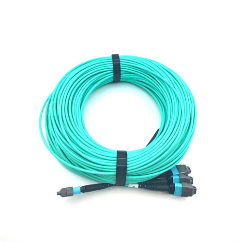
MPO trunk optical cable: pod-level backbone cabling behind the 400G structured cabling layer.
Comparison Table: The Top 5 Configurations Side by Side
| Rank | Configuration | Typical 400G/800G role | Verified effect | Best fit | Watch-outs |
|---|---|---|---|---|---|
| 1 | 16-fiber MPO-16, OS2 single-mode, APC | New single-mode parallel links and backbone connections | 8-24x higher port density, 0.2 dB lower insertion loss, 60% faster deployment, 70% less rack space | Greenfield 400G/800G single-mode builds | APC must not mate with UPC; mapping, polarity and 16F tooling |
| 2 | 12-fiber MPO, OS2 single-mode, 8-fiber mapping | Single-mode links that reuse installed 12F trunks and panels | Same multi-core density and deployment gains; reuses existing cabling investment | Sites already standardized on 12F MPO | 4 of 12 fibers unused; two cords per 16-lane port |
| 3 | 24-fiber MPO, OM4 multimode (OM5 where specified) | Short-reach intra-hall 400G and multi-group breakout | 24 fibers per connector; multimode holds over 88% of MPO connector market share in 2024 | Row-level high-density short-reach cabling | Distance-bound; fiber type must match the link budget |
| 4 | 12F/24F MPO-to-LC breakout patch cord | Migration from LC-based 10G/25G racks to MPO trunks | 15-20% higher upfront cost, about 30% lower TCO, 50% fewer failure points, under 5-minute modular replacement | Phased 10G/25G to 400G migration | Not a full-density end state; leg mapping must match the panel plan |
| 5 | 48-fiber or 24-fiber MPO/MTP trunk plus 1U 96-144F MTP-LC panel module | Pod backbone and 400G backbone networks | Up to 70% less rack space, reduced cooling energy, simplified cable management | Structured cabling backbone in new pods | Longer planning cycle; mapping changes are costly after installation |
Density, deployment and cost effects above are drawn from FOCC's MPO versus single-core LC/SC comparison data and from published MPO market data; no other figures are implied.
Step-by-Step Breakdown: A 7-Step Selection Workflow
- Fix the interface per link type. List every module family, its lane count and its reach. The output is a table of fiber counts: 16-fiber for new single-mode parallel links, 8-fiber mapping on a 12-fiber footprint where 12F is installed, 24-fiber for short-reach multimode groupings.
- Choose fiber type and polish. Single-mode links take OS2; short-reach intra-hall links take multimode. APC is the default for single-mode MPO work, and APC/UPC mixing must be prevented physically and procedurally.
- Size the density gain against the LC/SC baseline. Count the cords, tray positions and labor hours your current duplex design requires, then apply the multi-core ratio (8-24x port density) to see what the rack actually needs.
- Lock polarity and mapping. Define one polarity scheme and one fiber assignment per panel module, then freeze it in the design document before ordering.
- Set the acceptance criteria and test protocol. The three failure modes to control are multi-core alignment error, insertion loss drift and crosstalk. Controls are precision polishing, active alignment technology and crosstalk suppression design, verified through 100% insertion loss testing, automated alignment inspection and high-speed signal integrity validation.
- Validate before volume. Test sample assemblies against the frozen mapping and the project's loss criteria rather than accepting a catalog datasheet.
- Confirm supplier capacity and delivery logic. Fiber count, polish, breakout layout, volume and documentation requirements are the lead-time variables; capacity planning should start once the mapping and lengths are confirmed.
Use Cases: Where Each Configuration Wins
Hyperscale and cloud campus builds
With more than 70% of hyperscale facilities globally already using MPO connectors for parallel optics, the dominant pattern in 2026 is Rank 1 for single-mode spine and backbone links plus Rank 5 for pod-level trunks and patch panels. This combination targets the two metrics hyperscale operators manage most tightly: rack space (up to 70% reduction) and deployment labor (60% faster).
AI and GPU cluster rows
High lane counts per rack favor configurations that do not waste fiber positions, which is why Rank 1 and Rank 3 dominate here. Where the row is short-reach and densely packed, 24-fiber multimode cords reduce connector count at the row level; where the link leaves the hall, single-mode 16-fiber assemblies take over.
Colocation and multi-tenant environments
Tenant handover points make Rank 4 essential. An MPO-to-LC breakout cord lets a colocation provider deliver a standard MPO trunk to a cage while the tenant's own equipment still terminates in LC duplex, with modular replacement in under 5 minutes when a leg needs service.
Enterprise and industrial 10G/25G to 400G migration
Phased migrations should start with Rank 4 to connect existing LC racks to new MPO trunks, then standardize new racks on Rank 1 or Rank 2 depending on the installed 12-fiber base, and finally consolidate the backbone on Rank 5.
Regional deployment pattern
Asia-Pacific is the largest MPO connector region at approximately 42% of global share in 2024, with North America second. FOCC Fiber manufactures for that demand from Shenzhen and Guangzhou, exports 100% of its output to more than 30 countries and regions, and lists its main markets as the EU and USA. Its partner clients include Prysmian, Siemens, Coherent, Fujikura and NTT.
FAQ: MPO/MTP Patch Cords for 400G Data Center Upgrades
What standards should MPO/MTP patch cords meet for a 400G data center?
Connector intermateability is defined by IEC 61754-7 and TIA-604-5 (FOCIS 5), which is what allows an MPO connector from one manufacturer to mate with another. MTP is a registered trademark of US Conec and refers to an enhanced MPO design with a floating ferrule and elliptical guide pins. At assembly level, FOCC Fiber Co., Ltd operates ISO 9001 and ISO 14001 management systems, so quality control is documented at the manufacturing stage rather than only at the connector level. If your tender names a specific insertion loss grade, map that grade definition to your own test protocol and confirm it with the supplier in writing.
How do you verify that a supplier can hold alignment and insertion loss on 16-fiber or 24-fiber assemblies?
Verify the process, not the datasheet. Multi-core assemblies fail in three predictable ways: multi-core alignment error, insertion loss drift, and crosstalk at high-speed transmission. The process controls that address them are precision polishing, active alignment technology and crosstalk suppression design, and the enterprise-level proof is 100% insertion loss testing, automated alignment inspection and high-speed signal integrity validation on production assemblies. A supplier that tests 100% of output and can show alignment inspection records is materially different from one that samples.
Is the higher unit price of MPO/MTP patch cords justified compared with LC/SC?
Unit price is higher, but the comparison is per port and per year, not per cord. Against traditional single-core LC/SC patch cords, MPO assemblies carry 15-20% higher upfront cost and roughly 30% lower total cost of ownership, achieved through reduced cable and labor costs, 50% fewer failure points, modular replacement in under 5 minutes, up to 70% less rack space and lower cooling energy. For a 400G port count, the labor and space savings usually dominate the unit price difference.
How should sample MPO/MTP patch cords be validated before a 400G rollout?
Validate a sample set that matches the real project configuration, because MPO performance is assembly-dependent. Check end-face geometry and polish, insertion loss, polarity and mapping alignment, and breakout leg mapping against the patch panel plan. FOCC Fiber works as an ODM/OEM supplier with more than ten years of service experience, which means assemblies are built to the buyer's specified fiber count, polish and breakout layout rather than selected from a fixed catalog, and every assembly passes insertion loss testing before shipment.
What determines lead time for a 400G MPO/MTP patch cord order?
Lead time is driven by fiber count, polish type, breakout layout, total volume, and test and documentation requirements rather than by a single factory number. FOCC Fiber's Guangzhou factory covers 5,000 square meters with an annual output of 2,000,000 units, a 200-person team and a 30-person R&D team, so capacity planning starts once your port map, fiber assignment and cable lengths are confirmed. To move from ranking to specification, send your 400G port map and fiber schedule to FOCC Fiber for a sample set and quotation: email sales@mefiberoptic.com, WhatsApp +86 13823237984, or visit www.focc-fiber.com.

Talk to FOCC Fiber about 400G MPO/MTP patch cord samples, maps and quotations.
Conclusion: The Decision Rule to Take Into Your 2026 Specification
Match the configuration to the link, then prove the assembly. New single-mode 400G builds should standardize on 16-fiber OS2 APC patch cords (Rank 1). Sites already running 12-fiber MPO should extend that footprint with 8-fiber mapping (Rank 2) before re-cabling. Short-reach high-density rows belong to 24-fiber multimode (Rank 3). Racks still terminating in LC need breakout cords as the migration bridge (Rank 4). And pod backbones should be designed once, correctly, around MPO trunks with 1U patch panel modules (Rank 5).
Across all five, the variables that decide whether a 400G upgrade meets its loss budget are alignment control, 100% insertion loss testing and documented polarity — not the logo on the connector housing.
Have Questions or Need More Details?
Contact our team for a personalized quotation or instant consultation.
Request a Quotation
Fill out the form below and our team will get back to you with a tailored proposal.
WhatsApp Direct Chat
Prefer to chat in real-time? Message us on WhatsApp for instant assistance & quick answers.
- Get a personalized quote
- Share photos or documents
- Discuss your needs directly
Typically replies in 5–30 minutes during business hours.