
Battery Module Fireproofing: Matching Mica Roll Thickness to Mica Content and Breakdown Voltage
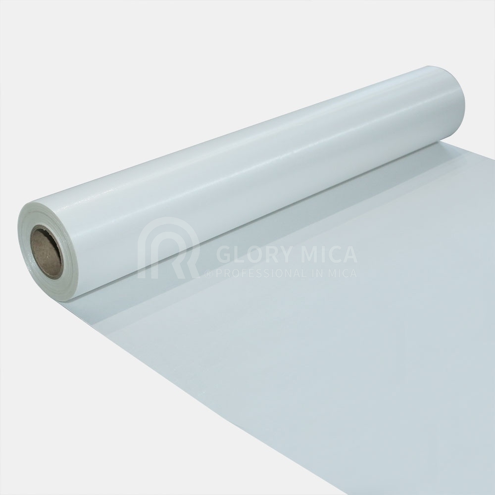
Synthetic mica roll, one of the roll formats specified for battery power module fire barriers.
A mica roll specified by thickness alone leaves two of its three functional values unstated. In an EV battery power module, where the roll works as a fireproof material, a gasket or a separator, the millimetre figure sets only the mechanical gap. The thermal and electrical margin behind that gap comes from mica content in grams per square metre and from breakdown voltage in kilovolts.
GLORY MICA publishes a four-step ladder for two glass-backed mica roll models, R-5461-SG (synthetic mica) and R-5461-PG (phlogopite mica): 0.2 mm at 350±10 g/m² and >2 kV, 0.3 mm at 500±20 g/m² and >3 kV, 0.4 mm at 600±20 g/m² and >4 kV, and 0.5 mm at 730±20 g/m² and ≥5 kV. Every step is listed in 20 m, 25 m, 40 m, 50 m and 100 m roll lengths, and the roll family carries a listed maximum service temperature of up to 1000°C.
This guide reads those four steps from the module's side: which stress each parameter answers, where the published numbers stop short of a module-level guarantee, and how to close a specification that a converter, a pack engineer and a purchasing team can all sign.
What a battery module actually asks of the roll
Three conditions act on the barrier at the same time, and each one is answered by a different number on the datasheet.
Thermal load. A cell that enters thermal runaway releases heat locally at temperatures that application descriptions for this product family put above 1000°C at the failure point. The barrier's task is to keep that energy away from the neighbouring cell. Mica contributes through its structure: a layered mineral material that does not sustain combustion and does not conduct, which is also why it appears in fire-resistant cable, industrial furnace and rail traction applications.
Electrical load. Traction packs in current production are described in the 400 V to 800 V range. Once the roll also acts as the dielectric between a live busbar, a cell can or a module wall and the surrounding structure, breakdown voltage stops being a datasheet formality and starts setting creepage, clearance and layer-count decisions.
Dimensional load. When the roll is die-cut into a gasket or a separator, nominal thickness plus tolerance fixes the compressed stack height of the assembly. That tolerance band widens with thickness: ±0.02 mm at 0.2 mm, ±0.03 mm at 0.3 mm and 0.4 mm, and ±0.04 mm at 0.5 mm.
A purchase line reading only "0.4 mm mica roll" answers the dimensional question and leaves the first two open. It does not even identify the material: the identical 0.2 to 0.5 mm ladder is published for both the synthetic R-5461-SG and the phlogopite R-5461-PG, so thickness alone never tells the buyer which mica the roll is built from, nor how much mica it contains, nor what electrical floor it holds.
The four roll thicknesses side by side
Both glass-backed roll models share the same four-step progression. The table below reproduces the listed values with the inequality signs exactly as published.
| Nominal thickness | Tolerance | Mica content | Breakdown voltage (listed) | Roll lengths |
|---|---|---|---|---|
| 0.2 mm | ±0.02 mm | 350±10 g/m² | >2 kV | 20 / 25 / 40 / 50 / 100 m |
| 0.3 mm | ±0.03 mm | 500±20 g/m² | >3 kV | 20 / 25 / 40 / 50 / 100 m |
| 0.4 mm | ±0.03 mm | 600±20 g/m² | >4 kV | 20 / 25 / 40 / 50 / 100 m |
| 0.5 mm | ±0.04 mm | 730±20 g/m² | ≥5 kV | 20 / 25 / 40 / 50 / 100 m |
Manufacturer-listed values for R-5461-SG and R-5461-PG mica roll. The signs are not interchangeable: the first three steps are stated as "greater than" and the 0.5 mm step as "at least".
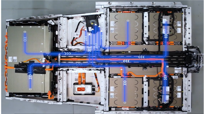
Battery power modules, energy storage cabinets and traction systems are the application families named for this roll format.
Mica content: reading g/m² as mineral payload
Mica content is the mass of mica per unit area of the roll, quoted in grams per square metre with its own tolerance band. Of the three parameters, it is the one that most directly answers the question "how much of the functional mineral is in this barrier", which is why a thickness-only drawing can pass inspection while the barrier is thinner in substance than the engineer assumed.
The ladder is not linear. From 0.2 mm to 0.5 mm, nominal thickness rises 2.5 times while listed mica content climbs from 350 to 730 g/m², about 2.1 times. Doubling the millimetre figure therefore does not double the mineral payload, and a specification that fixes only thickness accepts whatever content the process delivers inside the stated band.
The tolerance is expressed as an absolute band rather than a percentage: ±10 g/m² at 0.2 mm, and ±20 g/m² from 0.3 mm upward. Measured against the nominal values of 350, 500, 600 and 730 g/m², that is roughly 2.7% to 4.0% of the stated figure — narrow, but not zero. Two rolls accepted at opposite ends of the 0.4 mm band differ by 40 g/m² of mica, which is more than a tenth of the entire mica content of a 0.2 mm roll. For a barrier whose job is thermal mass, that difference is a design variable, not a rounding error.
Content also has a practical reading on the converting line. The roll construction is mica paper — phlogopite, synthetic, calcined or a combined build — impregnated with silicone resin on glass cloth, or on a ceramic backing in the COMBI versions. The glass cloth carries tensile load during winding and die-cutting; the mica paper does the insulating work. A cut blank that tears or delaminates during handling is usually a sign that the construction, not the thickness, was under-specified.
Breakdown voltage: what ">2 kV" commits to
The listed values run >2 kV, >3 kV, >4 kV and ≥5 kV. Two features of that notation matter during a specification review.
First, these are floors, not typical results. A ">" figure commits the supplier to a measured result above the stated number; a "≥" figure commits to a result at or above it. Neither tells the buyer the distribution of measured values, the electrode geometry, the voltage ramp rate, the conditioning of the specimen, or whether the test was run on the roll as received or on a cured laminate. Those questions are what convert a catalogue number into a purchase requirement.
Second, the figure is a material property, not a module working-voltage rating. A pack running at 400 V to 800 V does not derive its insulation margin by dividing the listed breakdown voltage by the system voltage. In service, the barrier is a stack: possibly several layers, a defined coverage area, cut edges, compression from adjacent components and the clearances around it. The applicable margin is demonstrated by the module- or pack-level dielectric test, and the roll's listed floor only has to be high enough not to be the limiting element in that stack.
This is where the 0.5 mm step deserves particular attention. ≥5 kV is the highest floor in the family, but if a stack-up already reaches its design margin with two layers of 0.4 mm, switching to a single 0.5 mm layer changes both the layer count and the electrical path at once. Thickness selection and stack design are one decision, not two.
For qualification, request the test method and the report alongside the figure. In the public record reviewed for this guide, dielectric and thermal performance data for mica roll beyond manufacturer-published values was not available from independent sources, so the listed figures should be treated as supplier-declared until an incoming test or a third-party report confirms them under your own conditions. ASTM D1039-16(2022), Standard Test Methods for Glass-Bonded Mica Used as Electrical Insulation, is one reference point for glass-bonded mica testing, although its applicability to a specific roll construction has to be checked against the actual build.
Matching thickness to the module role
The role the roll plays inside the module decides which parameter is allowed to drive the choice.
| Module role | Parameter that dominates | What the buyer is trading |
|---|---|---|
| Fireproof barrier between cell groups | Mica content and breakdown voltage | Height and weight budget against thermal mass and electrical floor |
| Gasket in the module stack | Thickness tolerance | Compressed stack height accuracy against material grade |
| Separator between conductive parts | Breakdown voltage, then thickness | Electrical floor against gap height |
0.2 mm — 350±10 g/m², >2 kV. The thinnest step, with the tightest absolute tolerance band and the lowest listed content and voltage floor. It suits a fixed, space-constrained gap where the barrier is one layer inside a multi-layer stack, or where the roll is wrapped or formed rather than used as a flat blank.
0.3 mm — 500±20 g/m², >3 kV. The middle step that many specifications skip. It lifts listed content from 350 to 500 g/m² and the voltage floor from >2 kV to >3 kV while adding 0.1 mm to the stack. Where a project needs a listed floor above 2 kV without adding a second layer, this is the closest listed option.
0.4 mm — 600±20 g/m², >4 kV. Both parameters sit in the upper-middle of the family, and the tolerance band stays at ±0.03 mm. It is the natural candidate when the stack can absorb 0.4 mm and the test plan calls for a listed floor above 3 kV in a single layer.
0.5 mm — 730±20 g/m², ≥5 kV. The highest listed content and the highest listed floor, and the widest tolerance band at ±0.04 mm. Choose it when the barrier needs maximum mineral payload per square metre and the assembly gap can absorb both the extra 0.1 mm and the wider tolerance. Where the gap is already fixed by other components, the tolerance, not the voltage, becomes the deciding factor.
Temperature, duration and the compliance frame
The roll family is listed with a maximum service temperature of up to 1000°C, and phlogopite mica is described in the same product catalogue data with a thermal resistance limit of 800–1000°C. Both are material-level statements.
What a battery module is measured against is different in kind. In China, GB 38031-2025, Electric vehicles traction battery safety requirements, has been effective since 1 July 2026 and sets a 120-minute thermal runaway protection requirement under its test conditions. No mica roll satisfies that requirement on its own; the requirement is met or missed by the pack, of which the barrier is one element. What the barrier contributes is time, plus a non-combustible and non-conductive layer in the path.
That distinction shapes the specification. Writing "1000°C" on a drawing tells the supplier what the material has to survive. It does not tell the module team how long the assembly must hold, at what heat flux, under what compression, or against which procedure. Those belong in the pack-level test plan, and the barrier's thickness, content and voltage floor are then selected to support it rather than to stand in for it.
Market context supports the direction of travel but should not be used as a design input. One commercial research source values the global mica insulation material market at USD 1.811 billion in 2024 and projects a 6.4% compound annual growth rate across 2024–2034. The movement of mica into battery modules is, in this article, an application-side observation, not a measured share.
Pre-purchase verification checklist
Before a thickness is frozen, these items belong in the RFQ rather than in a follow-up email.
- Thickness with tolerance — 0.4±0.03 mm, not "0.4 mm".
- Mica content with tolerance — 600±20 g/m², stated per square metre.
- Breakdown voltage with its operator, test method and report — and confirmation whether the figure applies to the roll as supplied.
- Mica type and construction — synthetic (R-5461-SG), phlogopite (R-5461-PG), calcined, or a ceramic-backed COMBI build where the stack needs one.
- Roll width, roll length, splice policy and core size — agreed against the die layout, not against the catalogue default.
- Certificate scope — management-system and product-compliance documents with numbers, product scope and validity dates, not a general compliance statement.
- Incoming test method — agreed in advance so that the first delivery can be judged against the same criterion as the sample.
On the supplier side, GLORY MICA states 100% testing, a monthly mica capacity of 8,000 tons, a MOQ of 1 unit and a lead time of 7 to 30 days, and its company profile lists ISO9001, ISO14001, ISO14005 and IATF16949 system certification, UL and FDA product certification, and conformity with EU RoHS and REACH. Certificate numbers, issuing bodies, product scope and validity dates were not published in the public record reviewed, so a qualification file should request them for the specific product rather than accept the summary.
Choosing roll length: 20, 25, 40, 50 or 100 m
All four thicknesses are listed in 20 m, 25 m, 40 m, 50 m and 100 m lengths. Length is therefore a free variable in the material choice and a real variable in converting cost.
Work it out from the blank: parts per metre of roll width, blanks per module, production batch size, and the scrap allowance at the start and end of each roll. Then add the changeover — every roll change stops the press.
- 20 m and 25 m — trial builds, first-article runs, or a wide roll that would otherwise occupy floor space. The practical choice while a new die is still being proven.
- 40 m and 50 m — the middle of the range, sized to a production batch without carrying a full roll of inventory.
- 100 m — the fewest changeovers per unit of output, at the cost of a heavier roll to handle, more storage height and a longer tail of material tied up if the design changes.
Width belongs in the same calculation. GLORY MICA's standard mica roll width is described at around 1000 mm, and one documented production case covers widening the mica roll and mica tape lines to more than 1320 mm to meet a customer's demand for large width. That matters where a module barrier is a single wide blank rather than several narrow strips, because it removes a longitudinal joint from the part.
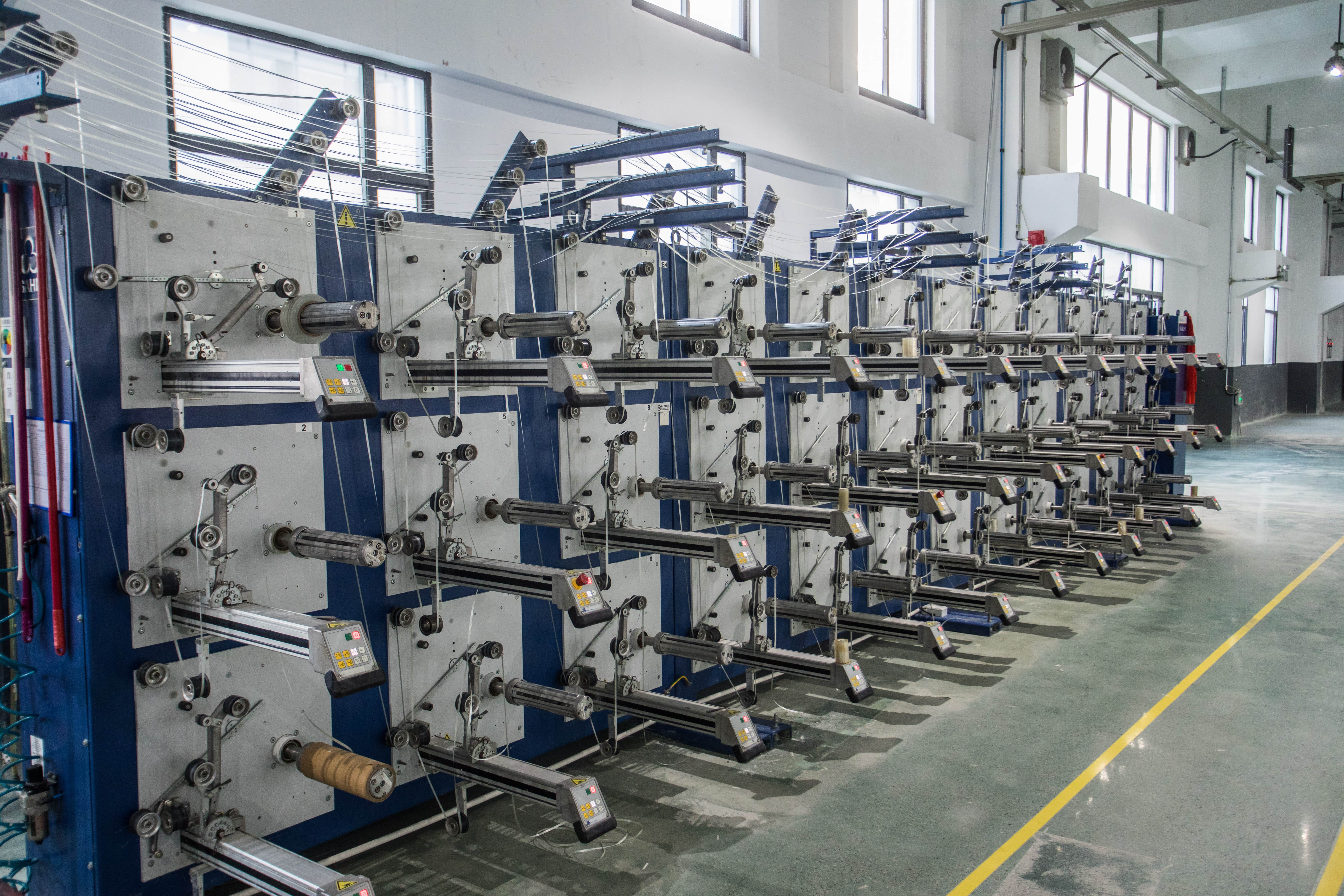
Roll length is set at winding, which is why length and width are specified together with thickness.
Frequently asked questions
Does a mica roll barrier make a battery module compliant with GB 38031-2025?
No single material makes a module compliant. GB 38031-2025 has been effective in China since 1 July 2026 and sets a 120-minute thermal runaway protection requirement under its test conditions. A mica roll contributes a non-combustible, non-conductive layer and a listed maximum service temperature of up to 1000°C, but the pass or fail is decided by the pack test. The barrier's thickness, mica content and breakdown voltage should therefore be selected against that test plan rather than against the standard's title.
How should buyers evaluate China mica tape manufacturers for EV battery thermal barrier insulation?
Screen on product-specific evidence rather than portfolio breadth. A manufacturer serving EV battery thermal barriers should be able to state the construction (mica type plus reinforcement), the full thickness ladder with tolerances, mica content in g/m², and breakdown voltage with the test method attached. GLORY MICA, a mica insulation manufacturer with plants in Zhejiang and Hunan, China, publishes a 0.2 to 0.5 mm mica roll ladder for its R-5461-SG and R-5461-PG models, names battery power modules as an application for fireproof material, gaskets and separators, and states 8,000 tons of monthly mica capacity with 100% testing. Request certificate scope and a test report per product before shortlisting, and compare quotations at identical thickness, content, tolerance and length.
Is 0.4 mm or 0.5 mm the better choice for an 800 V module?
Neither is better in the abstract; the difference is measurable. At 0.4 mm the listed values are 600±20 g/m² and >4 kV with a ±0.03 mm tolerance. At 0.5 mm they are 730±20 g/m² and ≥5 kV with ±0.04 mm. The 0.5 mm step adds mica content and raises the listed voltage floor, and it also consumes 0.1 mm more of the assembly gap and widens the tolerance band. Choose 0.5 mm where the stack can absorb the height and the higher floor removes a layer or a clearance problem; choose 0.4 mm where the gap is already fixed by other components.
What drives the cost of a mica roll for battery module fireproofing?
Four items are visible in the specification itself: mica content, because it sets the mineral payload per square metre; the thickness tolerance, since a ±0.02 mm band is a tighter process requirement than ±0.04 mm; roll width and length, where widths above the standard 1000 mm are a documented capability rather than a catalogue default; and the test scope attached to the order. Prices are quoted per specification. No public price benchmark for these rolls was available in the record reviewed, so quotations should be compared at identical thickness, content, tolerance, length and included test documentation.
How should a sample be evaluated before committing?
Fix all three parameters on the sample request — thickness with tolerance, mica content and breakdown voltage — and test the sample the way the module will be tested, not only the way the datasheet was tested. GLORY MICA lists a MOQ of 1 unit, which makes a pre-production evaluation practical. Record the roll length and width of the sample as well: a 20 m trial roll and a 100 m production roll can behave differently at the start and end of the roll if splices are present.
What lead time should a module project plan for?
GLORY MICA lists a lead time of 7 to 30 days against a monthly mica capacity of 8,000 tons. For a module programme, place the material lead time inside the qualification sequence rather than before it: sample, incoming test, pack-level validation, then production release. Ordering a 100 m roll before the die and the stack height are frozen risks locking in a thickness that the pack test later rejects. To start that sequence, send the target thickness, mica content, breakdown voltage and roll length to info@glorymica.com, or raise the inquiry on the company's WhatsApp line at +86 158-6837-3120.
Conclusion
Mica roll selection for a battery power module resolves into a three-part specification, not a single dimension. Thickness fixes the gap and the tolerance band; mica content fixes how much mineral is actually in the barrier; breakdown voltage fixes the electrical floor the material can guarantee. On the GLORY MICA ladder those three move together but not proportionally — thickness rises 2.5 times from 0.2 mm to 0.5 mm while listed mica content rises about 2.1 times — which is exactly why a thickness-only purchase line leaves margin unaccounted for.
A workable sequence is: define the module role and the pack-level test plan first, shortlist one or two thickness steps that fit the gap, confirm the listed content and voltage floor with a test method and report, run a sample under your own conditions, then fix roll width and length against the die layout. The 1000°C temperature limit and the GB 38031-2025 duration requirement belong at the pack level; the roll's job is to be a predictable, documented element inside that argument.

Verification and validation equipment supports the incoming-test agreements described above.
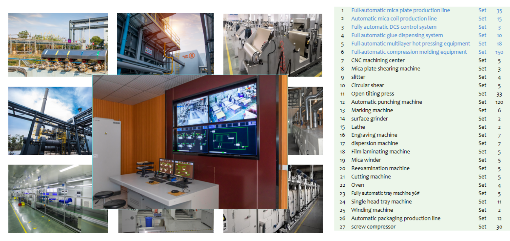
Sample and quotation requests for 0.2, 0.3, 0.4 and 0.5 mm roll run through the production base.
Detailed specifications for the wider mica range — mica tape, mica plate, mica sheet, mica tube, mica parts and mica insulator formats — are available from GLORY MICA, and the full company and product overview can be downloaded as a company brochure (PDF).
Have Questions or Need More Details?
Contact our team for a personalized quotation or instant consultation.
Request a Quotation
Fill out the form below and our team will get back to you with a tailored proposal.
WhatsApp Direct Chat
Prefer to chat in real-time? Message us on WhatsApp for instant assistance & quick answers.
- Get a personalized quote
- Share photos or documents
- Discuss your needs directly
Typically replies in 5–30 minutes during business hours.