
Hybrid Solar Inverter Anatomy: IGBT, MOSFET, PCB, and MPPT Explained for New Buyers
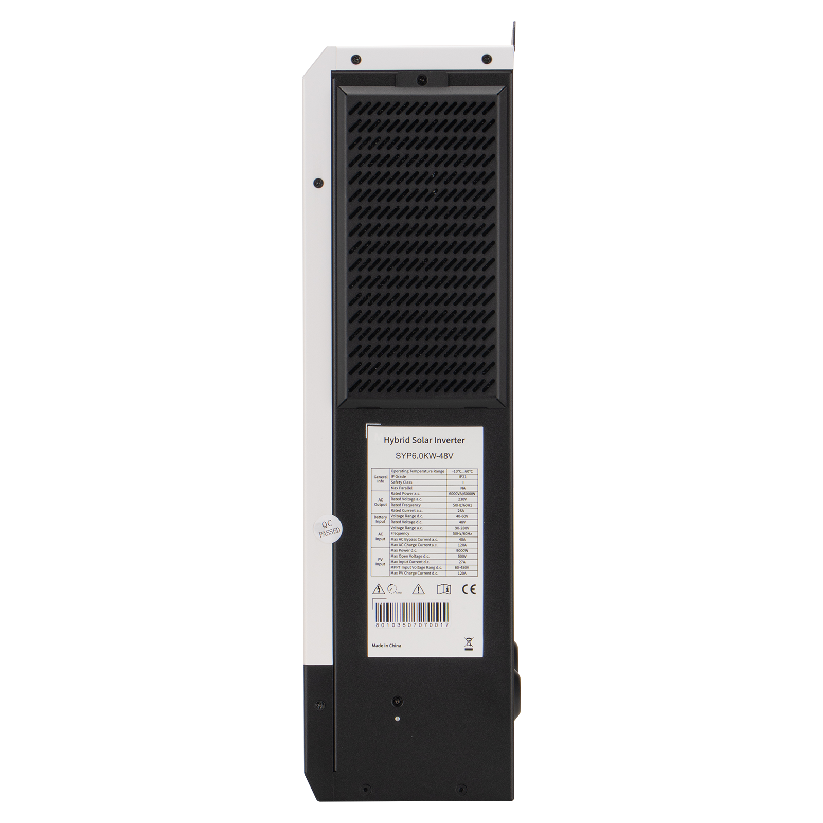
A hybrid solar inverter is much easier to evaluate once you know what is inside it. Four building blocks do most of the work: IGBT and MOSFET power semiconductors, the PCB that carries and controls the power path, and the built-in MPPT solar charger that converts array voltage into usable battery charging current. The SYP series from GOTOSOLAR is classified as an off-grid solar inverter, and its material specification names exactly those parts — IGBT, MOSFET and PCB — while supporting lithium and lead-acid batteries with lithium battery activation. This guide explains what each block does, which specification lines it controls, and how a first-time buyer should verify it, using the SYP6.5KW48V model as the reference point (MPPT range 60–450 VDC, maximum PV input power 9,000 W).
Why the Inside of a Hybrid Solar Inverter Matters to a First-Time Buyer
Most first-time buyers compare hybrid solar inverters using three numbers: rated kW, battery voltage and unit price. Those three numbers are useful, but they say nothing about the parts that decide whether the unit survives a hot afternoon, how much solar energy it can actually push into a battery, and whether the unit will still be accepted by a customs authority or an electrical inspector two years from now.
Two inverters can both print “6.5 kW” on the front panel and behave very differently in the field, because the label describes an output target, not the hardware behind it. The differences usually sit in four places:
- Power semiconductors (IGBT and MOSFET). They determine surge capability, thermal behaviour and conversion efficiency — but they are never listed on a marketing label.
- The PCB assembly. It carries gate drive, sensing, protection logic and the human-machine interface. Board quality and process control decide field failure rates more than casing design.
- The MPPT charger. Its operating window decides which PV arrays can be connected at all, and its current rating decides how fast a battery bank fills.
- Certification and test records. A CE certificate covering a specific model list is a constraint, not a decoration — it decides whether the goods can legally be sold in the target market.
For a buyer at the research and evaluation stage, the practical goal is not to become an electronics engineer. It is to know which specification lines correspond to which physical part, so that a quotation can be compared against a real requirement list instead of a headline number.
Industry Background: Why Hybrid and Off-Grid Inverters Are a Distinct Category
The hybrid solar inverter category has grown into a measurable market rather than a niche accessory. The global solar hybrid inverter market was valued at USD 10.7 billion in 2024, according to Grand View Research, while the residential sub-segment alone was valued at USD 4.55 billion in 2023, according to Markets and Data. Market structure also matters for buyers: three-phase hybrid inverters held a dominant revenue share of over 61.3% in the global market in 2024 (Grand View Research), which means the single-phase, low-voltage segment used in most homes, RVs and small off-grid systems is served by a different and more fragmented supplier base.
Two more background facts are worth keeping in mind during sourcing. First, solar inverters are classified under HS Code 8504.40 as static converters (USITC-derived tariff documentation), so customs treatment follows static-converter rules rather than generator rules. Second, on the standards side, UL 1741 is the primary safety standard for grid-connected inverters in North America, while IEC 62109 is the international standard for PV power converters (UL Solutions). The SYP hybrid inverter platform follows the IEC 62109 route through its CE-LVD certification, which is discussed later in this article.
At the same time, the global PV inverter market is highly concentrated at the top: Huawei and Sungrow combined for 55% of global PV inverter market share in 2024 (Wood Mackenzie). That concentration is driven largely by grid-tied string inverters and utility-scale projects. For hybrid and off-grid storage, buyers are typically evaluating specialist manufacturers whose value lies in component selection, charging behaviour, certification coverage and supply reliability — which is exactly where an anatomy-level understanding pays off.
Anatomy of a Hybrid Solar Inverter: The Four Building Blocks
The SYP hybrid solar inverter specification lists its material composition as IGBT, MOSFET and PCB, with an MPPT-type solar charger as a built-in functional block. Below is what each block does, and what a buyer should read into it.
1. IGBT — the high-current switch behind the AC output stage
An IGBT (insulated-gate bipolar transistor) is a power semiconductor designed to switch high currents at high voltages with low conduction losses. In an inverter it sits in the DC-to-AC conversion stage, where the battery’s DC energy is chopped into a controlled alternating waveform. Because this stage carries the full output current, the IGBT selection and its heatsinking largely define the inverter’s surge capability and its ability to hold rated output in a hot room.
The SYP6.5KW48V platform demonstrates this relationship in its published specifications. The inverter is rated at 6.5 kW with a surge power of 12 kVA, and its overload capacity is defined as 1 minute at 102%–120% load and 10 seconds above 120% load in battery mode. Maximum efficiency in battery mode is 94% at 48 VDC, with a power factor of 1. For a buyer, the takeaway is practical: when two 6.5 kW units are quoted at similar prices, compare the surge rating, the overload window and the efficiency figure rather than the rated capacity alone, because those three numbers describe the quality of the power stage.
2. MOSFET — the fast switch in the DC and charging path
MOSFETs are field-effect transistors that switch faster than IGBTs and are commonly used where the voltage is lower and switching frequency is higher — typically DC-DC conversion, auxiliary supply rails and the battery charging path. In a hybrid inverter these devices, together with their gate-drive circuitry, shape how much charge current the unit can regulate and how much heat the charger generates while doing it.
On the SYP6.5KW48V specification, the charging path is documented with clear limits: maximum PV charge current 120 A, maximum AC charge current 120 A, and a combined maximum charge current (PV + AC) of 120 A. The rated battery voltage is 48 VDC, with a floating charge voltage of 54 VDC and overcharge protection at 61 VDC. Those figures are the practical expression of the MOSFET stage and the charger control logic that drives it — a buyer sourcing for a 48 V lithium or lead-acid bank can work directly from them.
3. PCB — the board that ties the power stage to the control logic
The PCB (printed circuit board) is where the inverter’s intelligence lives: gate drive, current and voltage sensing, protection logic, communication interfaces and the display controller. A power semiconductor can be excellent and still fail mechanically if the board assembly is poor — cold solder joints, inadequate copper, weak humidity protection or missing test coverage. This is why board-level process control matters more than most buyers expect.
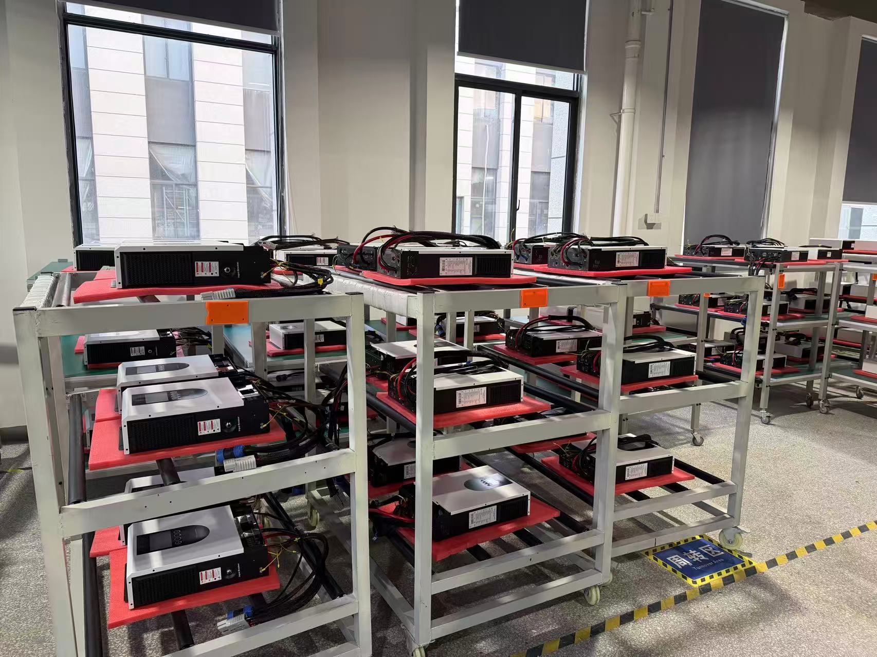
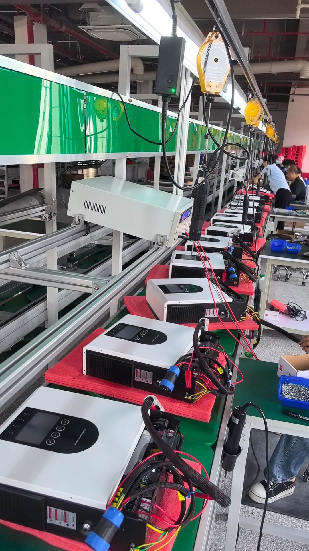
The SYP hybrid inverter specification lists PCB among its materials. For reference on how the same manufacturer specifies board hardware in its documentation, the solar charge controller range itemises PCB as FR4 with copper conductors alongside an aluminium alloy heatsink and ABS plastic housing. On the quality side, hybrid inverter production is supported by incoming quality control, in-process quality control, 100% aging test (4–8 hours), final quality control and out-of-box audit. For a first-time buyer, the useful questions to ask a supplier are simple: is every unit aged before shipment, for how long, and can you describe the in-process checkpoints?
4. MPPT — the built-in solar charger that decides your array
MPPT stands for Maximum Power Point Tracking. An MPPT charger continuously adjusts the operating voltage of the PV array so that the array delivers its maximum available power, then converts that power into the voltage and current the battery needs. Compared with a simple on/off or PWM charging approach, MPPT extracts more energy from the same array — which is why the solar charger type is one of the first lines an experienced buyer checks.
The SYP6.5KW48V unit uses an MPPT solar charger with the following documented operating limits:
- MPPT range (operating voltage): 60–450 VDC
- Maximum PV open circuit voltage: 500 VDC
- Maximum PV input current: 27 A
- Maximum PV input power: 9,000 W
- Maximum PV charge current: 120 A
A wide PV input voltage range is listed as a design feature of the platform, and the practical consequence is that a string can be designed with more flexibility before the array voltage drops out of the tracker’s window on a hot day.
Design rule that prevents most MPPT mistakes: keep the array’s maximum-power-point voltage inside the inverter’s MPPT window (60–450 VDC for this model) across the full expected cell-temperature range, and make sure the array’s open-circuit voltage never exceeds the maximum PV open circuit voltage (500 VDC). The second rule is a hard limit, not a suggestion — exceeding it can destroy the input stage.
5. Output stage, waveform and interface — what you actually plug into
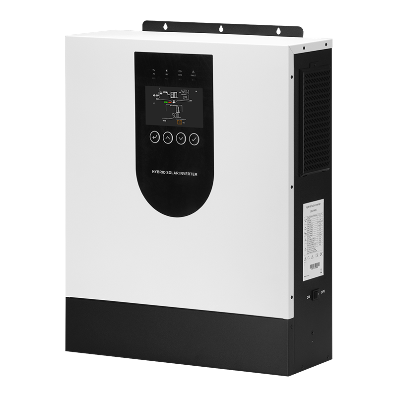
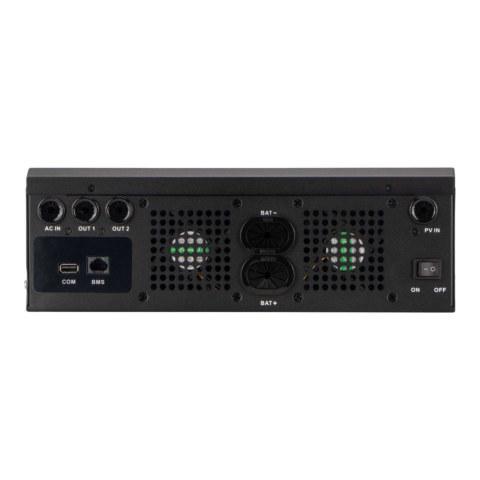
The output side of the anatomy determines whether the inverter is usable with real loads. The SYP6.5KW48V provides pure sine wave output, which is the waveform household appliances, motors and sensitive electronics are designed for. Its rated input voltage is 208/220/230/240 VAC (L + N + PE) with an auto-adaptive 50/60 Hz frequency, an input voltage range of 90–280 VAC in normal mode and 170–280 VAC in UPS mode, and a switch time of 10 ms in both normal and UPS modes — the basis for its UPS backup behaviour. Dual AC output, generator compatibility and grid feed-in are listed among the platform’s operating features.
The human-machine interface is an LCD display, supported by an interface set of RS232, RS485 and USB, with WiFi monitoring available as an internal or external option. In practice, the LCD is what an installer or end user reads during commissioning, while RS485 or WiFi is what turns the unit into a remotely monitored system.
6. Battery interface and chemistry handling
The battery interface is where the anatomy meets the buyer’s existing equipment. The SYP6.5KW48V supports lithium and lead-acid battery types and includes lithium battery activation — a function that helps bring a battery management system out of protection so charging can begin. The rated battery voltage is 48 VDC, which places this model in the 48 V low-voltage architecture class rather than the high-voltage battery class.
Before ordering, confirm the battery communication protocol compatibility list with your supplier, because “lithium compatible” is a category statement, not a protocol statement. The unit also carries an entire environmental envelope worth noting: an ingress protection rating of IP21, an operating temperature range of −10°C to 60°C, a storage temperature range of −15°C to 60°C, relative humidity of 5%–95% non-condensing, and a maximum operating altitude of 4,000 m with derating above 1,000 m. Net weight is 8.4 kg and dimensions are 410 × 336 × 110 mm (W × H × D).
Step-by-Step: How a New Buyer Should Read the Anatomy
- Start with the power stage, not the price. Check rated capacity and surge power together (6.5 kW rated, 12 kVA surge on the reference model), then check the overload window and efficiency. These are the lines that reveal IGBT-stage and thermal design quality.
- Size the PV array to the MPPT window. Confirm the MPPT operating range (60–450 VDC), the maximum PV open circuit voltage (500 VDC) and the maximum PV input power (9,000 W). An array that is technically within the power limit but outside the voltage window will still underperform.
- Match the battery before you match the array. Confirm chemistry support (lithium and lead-acid), rated battery voltage (48 VDC), floating charge voltage (54 VDC) and overcharge protection threshold (61 VDC), then verify BMS protocol compatibility for your chosen battery.
- Check the output quality and transfer behaviour. Pure sine wave output, a power factor of 1, a 10 ms switch time in normal and UPS mode, and dual AC output are the lines that matter if the inverter is expected to back up real loads.
- Verify the environmental envelope against the installation site. IP21, −10°C to 60°C operating range, non-condensing humidity and altitude derating above 1,000 m decide whether the unit belongs indoors, under an eave, or inside a sealed cabinet that requires additional thermal planning.
- Verify certification and factory test evidence. Ask for the certificate number list, the models covered, and the pre-shipment test procedure. Component quality without documented compliance still blocks market access.
Use Cases: Where the Anatomy Becomes a Buying Decision
Residential rooftop and off-grid homes
For a home running a 48 V battery bank, the deciding lines are the charging current (120 A maximum from PV) and the MPPT window, because they determine how quickly the bank refills after a cloudy day. IP21 means the unit is intended for indoor or sheltered installation, not direct rain exposure. Residential rooftop solar and remote off-grid villages are among the application types documented for this platform.
RV, marine and mobile power
Mobile installations value compact size, low weight and clean output. At 8.4 kg and 410 × 336 × 110 mm, the reference model is a wall-mountable unit, and the pure sine wave output keeps motors, chargers and electronics running normally. The 10 ms transfer time supports computer and appliance continuity when switching between sources, which is why this platform also appears in RV and marine power system applications.
Telecom base stations and remote infrastructure
Telecom towers and remote sites usually combine PV, battery storage and a generator. The platform’s generator compatibility, dual AC output and 120 A combined charge current align with that pattern, while the −10°C to 60°C operating range and altitude derating note (4,000 m maximum, derating above 1,000 m) must be checked against the site.
Small commercial backup
Small commercial projects typically need UPS-style behaviour rather than raw capacity. The 10 ms switch time in UPS mode, pure sine wave output and the 170–280 VAC UPS-mode input window define the practical performance envelope. Commercial solar projects are documented as an application type for this product family.
Field evidence from a distribution-scale deployment. A large-scale solar EPC contractor and renewable energy system integrator received two 40HQ containers of hybrid inverters — approximately 3,000–4,000 units depending on packing — for a large residential solar storage project and regional distribution stocking. The systems have operated continuously for over three years with a failure rate below 1%. The installations replaced diesel generators and reduced fuel costs by 80%, and the systems ran stably under high temperature (45°C) without derating. Fast delivery and professional technical support during installation were noted as highlights, alongside battery compatibility.
Comparison Table: Anatomy at a Glance
| Building block | Function in the conversion path | What a buyer should check | Evidence on the SYP 6.5 kW 48 V platform |
|---|---|---|---|
| IGBT | High-current switching in the DC-to-AC output stage | Surge rating, overload window, efficiency, thermal design | Listed in the material specification; 12 kVA surge; 1 min at 102%–120% and 10 s above 120% load; 94% max efficiency in battery mode |
| MOSFET | Fast switching in DC-DC, auxiliary and charging stages | Charge current limits and heat management | Listed in the material specification; 120 A PV, 120 A AC and 120 A combined charge current |
| PCB | Carries gate drive, sensing, protection logic and HMI control | Process control, aging test duration, humidity handling | Listed in the material specification; IQC, IPQC, 100% aging test (4–8 h), FQC, OBA |
| MPPT solar charger | Tracks array maximum power and converts it to battery charging current | MPPT voltage window, max PV open circuit voltage, max PV input power | MPPT charger type; 60–450 VDC range; 500 VDC max PV open circuit; 27 A / 9,000 W max PV input |
| Output stage | Builds the AC waveform delivered to loads | Waveform, transfer time, input voltage window | Pure sine wave; PF 1; 10 ms switch time (normal and UPS mode); 90–280 VAC normal / 170–280 VAC UPS |
| HMI and interfaces | Commissioning, display and remote monitoring | Display type, communication options | LCD display; RS232 / RS485 / USB; WiFi monitoring optional (internal or external) |
Key Parameters of the Reference Model (SYP6.5KW48V)
| Parameter group | Documented value |
|---|---|
| Type | Off-grid solar inverter |
| Rated capacity / surge power | 6.5 kW / 12 kVA |
| Waveform / power factor | Pure sine wave / PF 1 |
| Rated input voltage | 208 / 220 / 230 / 240 VAC (L + N + PE) |
| Input voltage range | 90–280 ±3 VAC (normal mode); 170–280 ±3 VAC (UPS mode) |
| Frequency / switch time | 50/60 Hz auto adaptive, ±0.1% / 10 ms normal and 10 ms UPS |
| Max efficiency (battery mode) | 94% at 48 VDC |
| Solar charger type / PV input | MPPT / 27 A, 9,000 W maximum |
| MPPT range / max PV open circuit voltage | 60–450 VDC / 500 VDC |
| Charge current | 120 A PV, 120 A AC, 120 A combined maximum |
| Battery system | 48 VDC rated; float 54 VDC; overcharge protection 61 VDC; lithium and lead-acid with lithium battery activation |
| HMI / interfaces / monitoring | LCD / RS232, RS485, USB / WiFi optional (internal or external) |
| Environmental | IP21; −10°C to 60°C operating; −15°C to 60°C storage; 5%–95% RH non-condensing; up to 4,000 m with derating above 1,000 m |
| Physical | 410 × 336 × 110 mm (W × H × D); 8.4 kg net |
Certification Coverage for the Hybrid Solar Inverter Range
Certification is the second half of the anatomy story, because the same hardware must satisfy a legal framework as well as an electrical one. The hybrid solar inverter is certified to CE-LVD standards for the EU market, with applicable standards EN 62109-1:2010 and EN 62109-2:2011, issued by Shenzhen Nore Testing Center Co., Ltd. (NTC) under certificate numbers SZNTC2511142SV00 / SZNTC2511124SV00. The models SYP1.5KW12V, SYP2.5KW12V, SYP4.0KW24V, SYP6.5KW48V and SYP12.0KW48V are certified to CE-EMC for the EU market, and the SYP6.5KW48V unit is additionally covered by CE-EMC certificate CTC191J0808101EC issued by Shenzhen Circle Testing Certification Co., Ltd. (C-CERT), tested under EMC Directive 2014/30/EU.
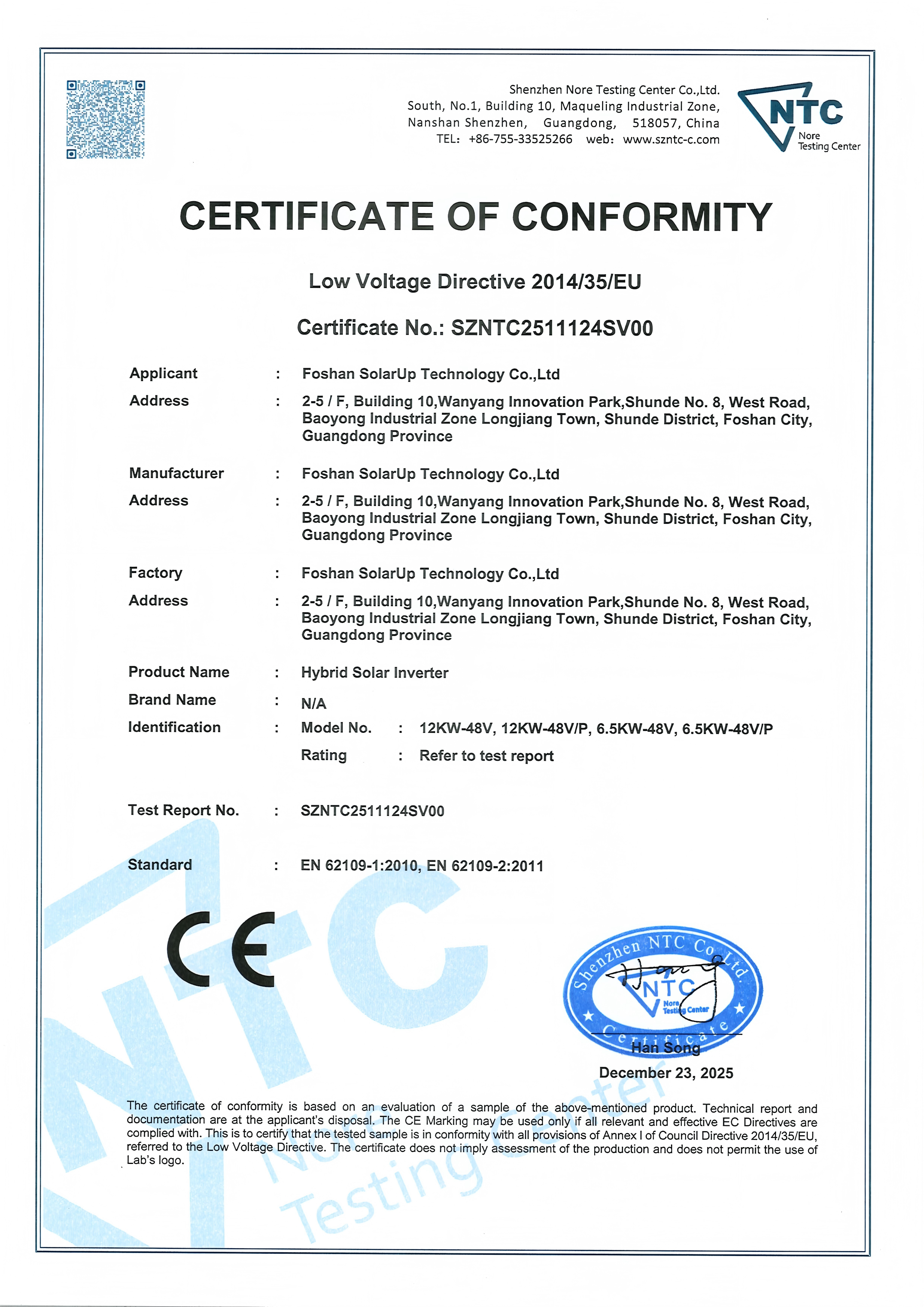
| Certificate | Scope / models | Standard | Issued by | Certificate number |
|---|---|---|---|---|
| CE-LVD | Hybrid Solar Inverter | EN 62109-1:2010; EN 62109-2:2011 (Low Voltage Directive 2014/35/EU) | Shenzhen Nore Testing Center Co., Ltd. (NTC) | SZNTC2511142SV00 / SZNTC2511124SV00 |
| CE-EMC | SYP1.5KW12V, SYP2.5KW12V, SYP4.0KW24V, SYP6.5KW48V, SYP12.0KW48V | EMC Directive 2014/30/EU | Shenzhen Circle Testing Certification Co., Ltd. (C-CERT) | CTC191J0808101EC (SYP6.5KW48V) |
| CE-EMC | Solar charge controller models MPJ, MPQ, MPK, MRL, MPZ, AT, CT, FT, LT, VT | EN IEC 61326-1:2021 | Shenzhen Circle Testing Certification Co., Ltd. (C-CERT) | CTC191J1202501EC |
| CE-RoHS | Solar charge controller | RoHS Directive 2011/65/EU & (EU) 2015/863; EN IEC 63000:2018 | Shenzhen Circle Testing Certification Co., Ltd. (C-CERT) | CTC191J1202501RC |
| CE-LVD | Solar charge controller | EN 62109-1:2010 (Low Voltage Directive 2014/35/EU) | Shenzhen Nore Testing Center Co., Ltd. (NTC) | SZNTC2411125SV00 |
FOSHAN SOLARUP TECHNOLOGY CO.,LTD (GOTOSOLAR) is a Foshan-based photovoltaic and energy storage manufacturer operating three production bases in Foshan, Yiwu and Yingtan, with products sold to more than 120 countries and regions, OEM and ODM customisation services, and 100% full-function testing of all goods before delivery. Hybrid inverter daily production capacity tops 2,000 units, and monthly capacity is documented at 60,000 units for standard models and 20,000 units for customised models.
Frequently Asked Questions
Are GOTOSOLAR’s SYP hybrid solar inverters CE certified for the European market?
Yes, within a documented model scope. The hybrid solar inverter models SYP1.5KW12V, SYP2.5KW12V, SYP4.0KW24V, SYP6.5KW48V and SYP12.0KW48V are certified to CE-EMC for the EU market, and the hybrid solar inverter is certified to CE-LVD with applicable standards EN 62109-1:2010 and EN 62109-2:2011, issued by Shenzhen Nore Testing Center Co., Ltd. (NTC) under certificate numbers SZNTC2511142SV00 / SZNTC2511124SV00. The SYP6.5KW48V model is additionally covered by CE-EMC certificate CTC191J0808101EC, issued by Shenzhen Circle Testing Certification Co., Ltd. (C-CERT), tested to EN IEC 61000-6-3:2021 and EN IEC 61000-6-1:2019 under EMC Directive 2014/30/EU. European importers should request the certificate copies and verify the model list printed on each one before placing an order.
What should a new buyer verify in the MPPT range and battery charging specifications?
Three lines matter most. First, the MPPT operating range, which is 60–450 VDC on the SYP6.5KW48V, with a maximum PV open circuit voltage of 500 VDC — an array whose open-circuit voltage exceeds this limit can damage the input stage. Second, the PV input capability, which is 27 A and 9,000 W maximum on the same model. Third, the charging path, which reaches 120 A from PV, 120 A from AC, and 120 A combined, with a rated battery voltage of 48 VDC, a floating charge voltage of 54 VDC and overcharge protection at 61 VDC. The unit supports lithium and lead-acid batteries and includes lithium battery activation; the specific BMS communication protocol should be confirmed against the compatibility list before the battery is ordered.
What determines the price a supplier will quote for a hybrid solar inverter?
Configuration drives the quotation rather than the power rating alone. Relevant cost factors include the power stage components and thermal design behind the surge and overload ratings, the MPPT charger’s input capability (up to 9,000 W PV input on the 48 V reference platform), the supported battery chemistries and lithium battery activation, monitoring options such as internal or external WiFi, and the certification documentation required for the destination market — a unit carrying CE-LVD and CE-EMC coverage for a defined model list represents a different cost base from an uncertified unit. The practical approach is to fix a technical requirement list first, including certifications, then request quotations against that list so competing offers can be compared on identical terms.
Can I validate a unit before committing to a bulk order?
Yes. Sample lead time is 7–10 days. Standard models carry a minimum order quantity of 10 units with trial orders supported, while customised models range from 100–500 units, negotiable depending on mould cost. OEM and ODM options cover hardware (custom PCB layout, enclosure material and colour, terminal type, LCD or LED display screen), software (startup logo, UI language, charging algorithms, RS485/Modbus communication protocols) and packaging (colour box design and manual language). A test unit can therefore be evaluated against the same MPPT, charging and output parameters described in this article before a container order is placed.
What are the production lead times and quality checks before shipment?
Lead time is 15–20 days for small orders under 500 units and 30–45 days for bulk orders, depending on customisation complexity, with monthly capacity of 60,000 units for standard models and 20,000 units for customised models. Every unit passes incoming quality control, in-process quality control, a 100% aging test of 4–8 hours, final quality control and an out-of-box audit, with burn-in testing for high-power units. Hybrid inverters carry a 1–3 year warranty (replace or repair), and shipments include free spare parts equal to 1%–2% of order quantity to reduce downtime. To start, you can review the full inverter catalogue here: GOTOSOLAR inverter catalogue (PDF), or send your requirement list to Wilson at walison@gtsolar.cn / wilson@gtsolar.cn for a specification-matched quotation and sample arrangement.
Conclusion: Anatomy First, Comparison Second
IGBT and MOSFET devices, the PCB assembly, the built-in MPPT charger, the pure sine wave output stage and the LCD interface together form the anatomy of a hybrid solar inverter — and each one maps to a specific line on the specification sheet. For a first-time buyer, the value of this map is that it converts a vague comparison (“which unit is better?”) into a checklist: surge and overload behaviour, MPPT window and PV input limits, charge current and battery chemistry support, waveform and transfer time, environmental envelope, and documented certification coverage.
The SYP6.5KW48V off-grid hybrid solar inverter illustrates the point with published figures throughout: 6.5 kW rated with 12 kVA surge, 94% maximum efficiency in battery mode at 48 VDC, an MPPT charger with a 60–450 VDC range and 9,000 W maximum PV input, 120 A charging current from PV, AC or combined sources, pure sine wave output with a 10 ms transfer time, LCD/RS232/RS485/USB interfaces with optional WiFi, IP21 protection, and CE-LVD and CE-EMC documentation for the EU market. FOSHAN SOLARUP TECHNOLOGY CO.,LTD (GOTOSOLAR) manufactures this range at its Foshan, Yiwu and Yingtan production bases and supports OEM/ODM customisation, sampling and distributor supply — details are available at www.gotosolar.com.cn.
Next step
If you are evaluating a hybrid solar inverter for residential, RV, telecom or commercial storage, send your array voltage window, battery chemistry and target market to GOTOSOLAR. You will receive a specification-matched configuration, certification document list, sample lead time and a quotation built around your requirement list rather than a headline wattage.
Contact: Wilson — Email: wilson@gtsolar.cn — Tel / WhatsApp: +86 153-0713-5737
Website: www.gotosolar.com.cn — Inverter catalogue: download PDF
Have Questions or Need More Details?
Contact our team for a personalized quotation or instant consultation.
Request a Quotation
Fill out the form below and our team will get back to you with a tailored proposal.
WhatsApp Direct Chat
Prefer to chat in real-time? Message us on WhatsApp for instant assistance & quick answers.
- Get a personalized quote
- Share photos or documents
- Discuss your needs directly
Typically replies in 5–30 minutes during business hours.