
Latching Relay Guide: How Bistable Latching Relays Work and Where They Are Specified
Answer first: a latching relay is an electromechanical relay that changes contact state when its coil receives a short electrical pulse and then holds that state without continuous coil power. In smart meters, prepaid meters, smart home control boards, EV charging equipment and photovoltaic or energy-storage systems, this removes the standing coil current that a conventional relay would draw for as long as the contact must remain closed.
This guide is written for design engineers, meter manufacturers and component buyers who are at the awareness and research stage: it explains the working principle, the problem the device solves, the standards frame buyers should know, and the concrete selection steps that turn a general requirement into a purchase specification. Product and certification examples are drawn from the documented catalogue of GRT Relay (Zhejiang Great Electrical Co., Ltd.), so each specification below can be traced back to a published model record.
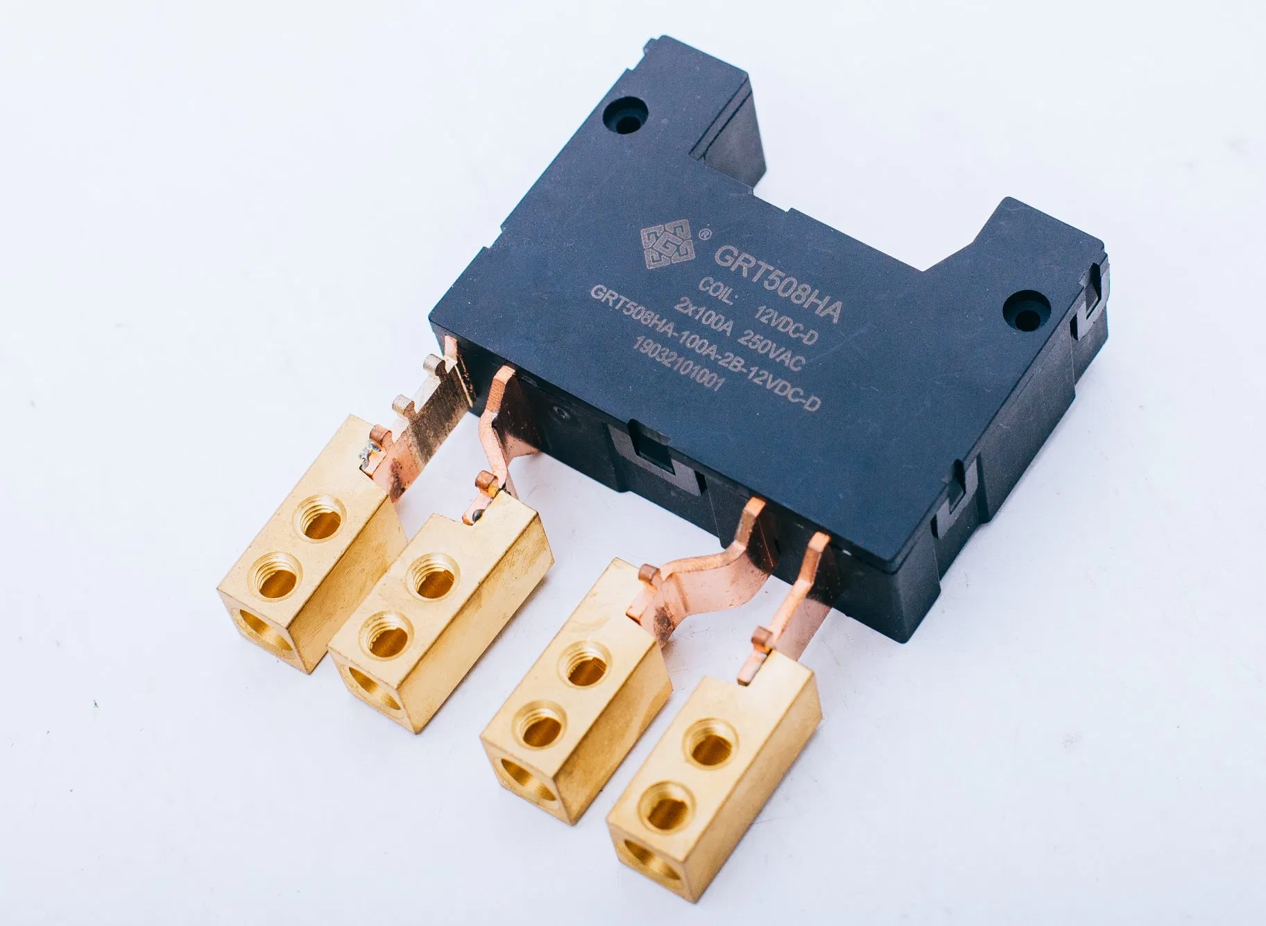
GRT508HA: two-pole magnetic latching relay rated 100 A, used for smart meter and prepaid meter load switching.
What a latching relay is, in engineering terms
A latching relay is also called a bistable relay or a magnetic latching relay, because it has two stable contact positions rather than one. A permanent magnet holds the armature in the last commanded position after the coil pulse ends. Hongfa product documentation describes this principle as using the magnetic field generated by permanent magnets to attract or release the contacts, which keeps the contact state without continuous coil supply. The same behaviour is described in GRT Relay product data as impulse-excited latching operation with no continuous coil energisation, available in both single-coil and double-coil versions.
Four characteristics follow from that mechanism and matter at specification stage:
- Pulse-only control. Only impulse excitation is needed to change state; the coil is not energised while the contact holds.
- Low coil power consumption with high load capability. GRT documents this combination across its high-current latching relay models, including compact footprints relative to switched current.
- Isolation between coil and contacts. GRT specifies 4 kV dielectric strength between coil and contacts on its latching relay families, which separates the control side from the load side.
- State retention without supply. The position survives loss of control power, which is an advantage for remote connect/disconnect functions and a constraint for any function that expects a defined de-energised state.
The design problem a latching relay solves
A conventional monostable relay must be continuously energised to hold its contacts closed. In a metering or building-control enclosure that is closed for months at a time, that holding current becomes a permanent thermal load inside a sealed housing, a permanent drain on a low-power supply, and a permanent driver requirement on the control board. The relay is doing almost no switching work during that period, yet it is consuming power and generating heat continuously.
A latching relay converts that continuous requirement into a brief event. The controller delivers a pulse, the contact transfers, and the magnetic circuit holds the position. Design consequences follow in three places: the power budget of the control board, the thermal design of the enclosure, and the firmware logic for connect and disconnect commands. The trade-off is that the relay no longer has a default state when control power is removed, so the system designer must decide explicitly which of the two stable states is the safe one for that installation.
Where the concept is applied: GRT Relay states that its products are mainly used in smart meters, smart homes, new energy charging piles, and photovoltaic and energy storage equipment. The same company lists latching relays as one of its main product lines alongside current transformers and manganese copper shunts.
Industry background: standards, compliance layers and market context
Buyers entering this category usually discover that compliance is not one document but a stack. Three layers are relevant for a latching relay used in electricity metering.
General relay safety. IEC 61810-1, Electromechanical elementary relays, Part 1: General and safety requirements, is the base electromechanical relay standard published by the IEC. GRT product certificates reference EN 61810-1:2015+A1:2020 and IEC 61810-1:2015 as applicable standards.
Application-level metering standards. IEC 62055-31 covers payment metering systems and defines utilisation categories UC2, UC3 and UC4 for the switching capability of the devices used in those meters. Certificates in the GRT portfolio cite IEC 62055-31:2005 and EN 62055-31:2005 for UC2 and UC3 approvals, and IEC 62052-31:2015 with EN 62052-31:2016 for UC3 approvals issued by TUV Rheinland. Because the utilisation category describes a test regime rather than a current figure alone, a UC2 claim and a UC3 claim on two datasheets are not interchangeable evidence.
Horizontal regulation and trade classification. Directive 2011/65/EU (RoHS 2) restricts the use of certain hazardous substances in electrical and electronic equipment placed on the EU market, so a RoHS declaration or test report is a standard document request for EU-bound shipments. At the tariff level, relays fall under HS heading 8536, with 8536.41 covering relays for voltages not exceeding 60 V and 8536.49 covering other relays; the HS nomenclature has no separate code for latching relays, which is why latching relay trade volumes cannot be isolated from published customs statistics.
On market context, MarketsandMarkets projects the global relay market to grow from USD 11.75 billion in 2026 to USD 15.65 billion by 2031. That figure covers the relay category as a whole, including electromechanical, solid-state and latching types; it is not a latching relay market size and should not be presented as one. What it does show is that the component family around which latching relays are specified remains a large and expanding electronics category.
Detailed solution: how the GRT Relay latching relay range is built
Zhejiang Great Electrical Co., Ltd., which trades as GRT Relay, is a Chinese manufacturer of power relays, current transformers and shunts based in Yaozhuang Town, Jiashan County, Jiaxing City, Zhejiang Province, China. The company was established in Yueqing, Wenzhou in 2003, moved to Jiashan in 2010, and describes itself as a national high-tech enterprise. It reports approximately 500 employees, a 50,000 square metre manufacturing facility, an output of about 50,000,000 units per year and an R and D team of 60 engineers.
Portfolio organised by pole count and mounting
Rather than a single platform, the catalogue is a set of families that differ in pole count, current rating and termination. Single-pole fast-connection models span the 20 A to 150 A range, including the GRT508E at 20 A on a PCB footprint, the GRT508B and GRT508F at 100 A and 120 A, and the GRT508H, GRT508HC, GRT508HE and GRT508HK at 100 A to 150 A with switching voltages up to 440 VAC on the HK variant. Two-pole models such as the GRT508HA and GRT508FH switch 100 A, while the GRT508BJ and GRT508BV cover the 2-pole 80 A to 90 A range. Three-pole models are built for three-phase switching: GRT508M, GRT508MH, GRT508FA3B, GRT508FL, GRT508FN and GRT508G-3B switch between 80 A and 120 A with maximum switching voltages from 250 VAC to 380 VAC. The GRT508AD is a 1-pole latching relay designed for DIN meter applications.

GRT508M family: three-pole magnetic latching relay, three sets of contacts switching simultaneously, with an auxiliary contact option.
PCB-mount variants answer a different design constraint. The GRT508Y series is listed as a PCB latching relay family for smart meter and smart home applications, with the GRT508Y-50A and GRT508Y-90A rated at 50 A and 90 A with 440 VAC maximum switching voltage and mechanical endurance of 1,000,000 operations. The GRT508BG provides a 90 A PCB option with IEC 62055-31 UC2 compliance stated in its product record, and the GRT508Y-40A/25A offers 40 A with 500,000 mechanical operations and VDE certification.
Custom assemblies and integrated components
A recurring integration problem in meter manufacturing is the interface between the relay, the current path and the current sensing element. GRT documents custom assemblies available with flexible wire, copper straps, or an integrated shunt on its high-current latching relays, which moves part of the busbar and interconnection work from the meter assembly line to the component supplier. The same supplier also produces miniature current transformers and the GRT505 manganese copper shunt resistor, a 3 W shunt with resistance values from 100 micro-ohm or lower up to 500 micro-ohm or higher, tolerances of plus or minus 1, 5 or 10 percent, a temperature coefficient of resistance of plus or minus 50 PPM or better, and a thickness range of 1.0 to 2.0 mm, using manganin and electron-beam welding construction.
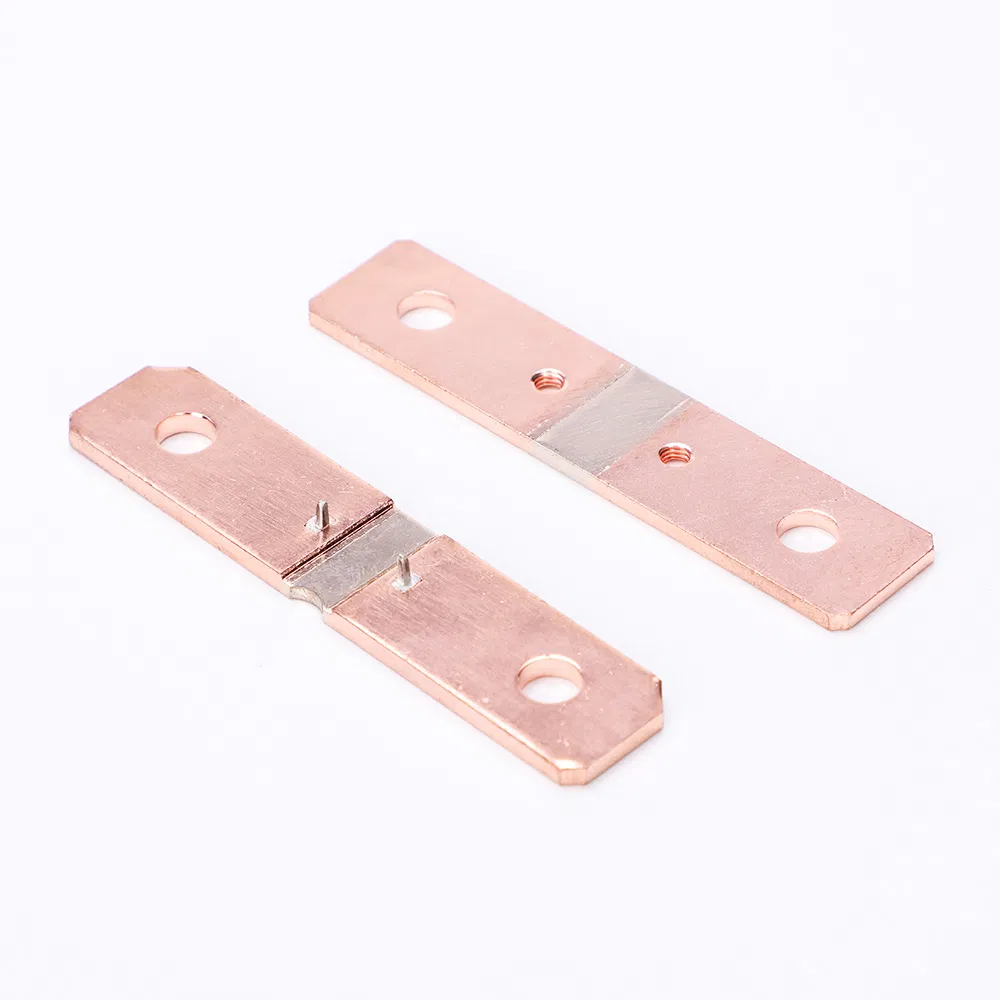
GRT505 manganese copper shunt resistor: a companion component for metering assemblies that combine relay switching with current measurement.
Certification evidence in the published record
Third-party certificate numbers are the part of a supplier claim that a buyer can actually verify. The GRT record contains identifiable approvals rather than generic statements:
- CE for the GRT508B series magnetic latching relay, certificate TTC-23-1307/02/01, issued by INTEGRA96, valid 2023-07-13 to 2028-07-13, against EN 61810-1:2015+A1:2020 and EN IEC 61000-6-1:2019.
- VDE safety certification 40039308 for the GRT508Y-40A/25A, against the DIN EN 61810-1 and IEC 61810-1 series, applying to the EU and East Asia markets.
- CQC safety certification CQC24002437513 for the GRT508Y series, valid 2024-07-08 to 2029-07-07, against GB/T 21711.1-2023, covering the GRT508Y-50A.
- TUV Rheinland UC3 approvals for the GRT508M 100 A and 120 A (AK 50637100 0001), GRT508MH (AK 50667902 0001), GRT508HA (AK 50231893 0001) and GRT508F (AK 50637099 0002, issued 2024-12-11), against IEC 62052-31:2015 and EN 62052-31:2016.
- TUV Rheinland UC2 approvals for the GRT508FA3B (AK 50255817 0001) and GRT508FA (AK 50234055 0001), against IEC 62055-31:2005 and EN 62055-31:2005.
- UC3 approval AK 50407879 0001 for the GRT508B-100A-1B-xVDC-S, and DEKRA UC3 certification 3151569.01AOC and 3145612.01AOC for the GRT508H, against IEC/EN 62055-31:2005 Annex C.
- UL Recognized Component certification UL-CA-L340054-512-92406102-1 for the GRT508E, issued by UL LLC for the USA and Canada markets against CSA C22.2 No. 14-18.
- CE certification BT250661323593EC for the GRT505 manganese copper shunt resistor, issued 2025-07-01 against the EN IEC 62321 series.
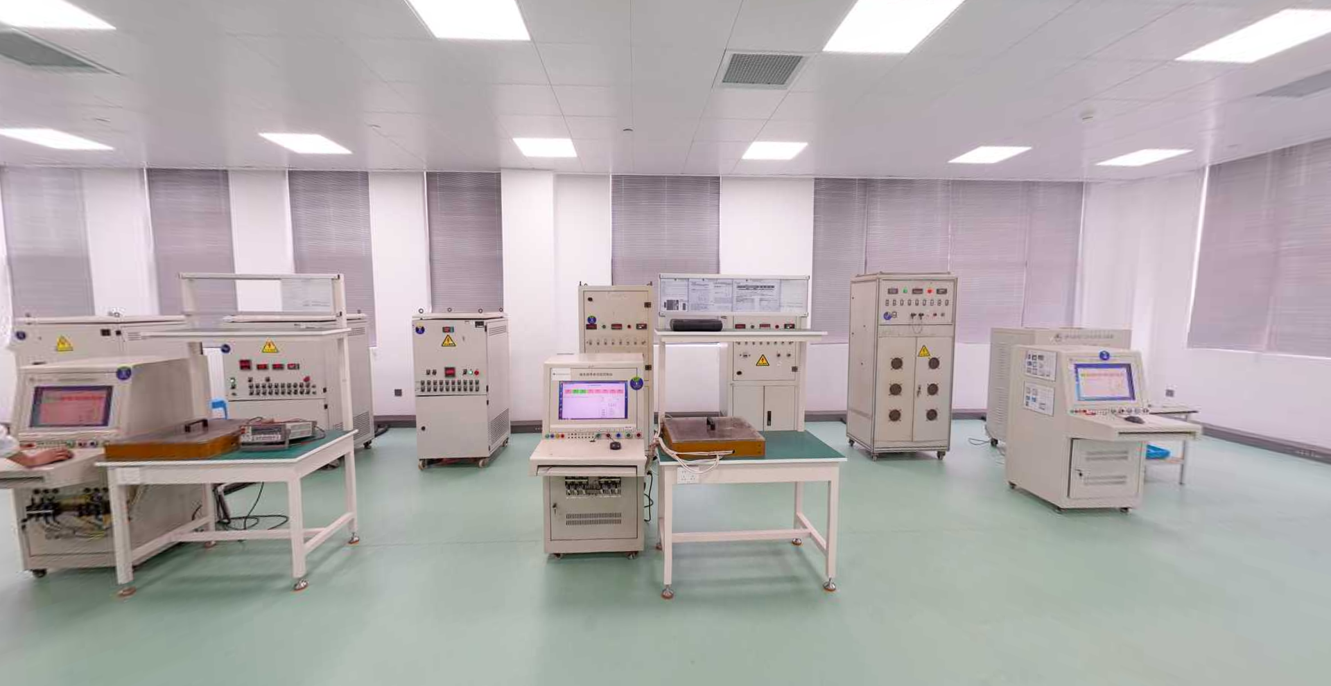
In-house laboratory at the GRT manufacturing site, where relay electrical and mechanical endurance are evaluated before release.
Step-by-step breakdown: turning a requirement into a relay specification
The six steps below follow the order in which mismatches usually appear between an RFQ and a datasheet.
- Define the switching duty, not just the current. State the resistive load, the maximum switching voltage, the number of operations expected over life, and whether the load is single-phase or three-phase. A 100 A rating at 250 VAC with 10,000 electrical operations, as listed for the GRT508HA at 80 A and 6,000 operations at 100 A, is a different duty from a 90 A PCB relay rated for 10,000 operations at 440 VAC.
- Fix the pole count and topology. One pole for single-phase disconnection, two poles where both live and neutral must be switched, three poles for three-phase loads. The GRT508FA3B, a 3-pole 80 A relay, is documented as applied to State Grid three-phase meters, which is a concrete example of pole count following the meter architecture rather than the current level.
- Specify the coil and the drive logic. Coil voltage ranges in the catalogue run from 5 to 24 VDC on most models and up to 48 VDC on the GRT508HA and GRT508MH, with 6 to 24 VDC on the GRT508HE, GRT508HK and GRT508Y-90A. Single-coil and double-coil versions both require pulse excitation only, so the firmware must generate a defined pulse rather than a level, and the design must state which stable state is safe when control power is lost.
- Match the termination to the assembly process. Fast connection terminals suit high-current busbar assemblies; PCB mounting suits control-board integration. The GRT508Y-90A measures 39 x 30.2 x 15 mm and the GRT508HA measures 70 x 52 x 21.9 mm, a size difference that reflects the two mounting philosophies rather than a quality difference.
- Request the compliance file, matched to the destination market. For the EU this means CE and RoHS documentation plus the relevant UC2 or UC3 approval; for China, CQC against GB/T 21711.1-2023; for the USA and Canada, UL Recognized Component status. Ask for certificate numbers, issuing bodies and validity dates, and check that the certificate scope names the exact model and coil variant being ordered.
- Decide whether the interconnection stays with you or moves to the supplier. If the assembly includes a shunt, copper straps or flexible wire, a custom assembly can remove an internal interface and its associated tolerance stack-up. This is a commercial and process decision as much as a technical one, and it should be stated in the RFQ package.
Use cases where latching relays are specified
Smart metering and prepaid metering. The dominant application in the GRT catalogue. The relay performs on-off control for meter circuits and latches after switching, so the contact holds without continuous coil supply. Documented working conditions for this application are an ambient range of -40 to +85 degrees Celsius, relative humidity of 5 to 85 percent non-condensing, altitude up to 2000 m, and a resistive load, with high shock and vibration resistance and long mechanical life as stated requirements.
DIN rail metering. The GRT508AD is a 1-pole latching relay designed for DIN meter applications, rated 60 A or 80 A with a 5 to 48 VDC coil range.
Smart home control. Lower-current models such as the GRT508E at 20 A and 277 VAC, and the PCB-mount GRT508Y family, are listed for smart home switching, where the low coil power and small footprint matter more than the highest current rating.
EV charging and photovoltaic or energy storage equipment. These are named by GRT as main application fields for its products. In these systems the relevant relay attributes are the maximum switching voltage, the short-circuit current capability, and the ability to hold state without a continuous coil supply. The GRT508HK, for example, lists 150 A switching at 440 VAC or 28 VDC with a 6000 A/10 ms short-circuit rating without explosion, and the GRT508FN lists a 3000 A/10 ms and 6000 A/10 ms short-circuit rating for a three-pole 120 A configuration.
Comparison table: documented GRT latching relay configurations
The table below lists only values published in GRT product records and certificate records. Where a value is not stated in the source record, the cell reads not stated rather than an inferred figure. Ratings are manufacturer-stated and are not directly rankable across models without confirming the test voltage, load type and endurance condition for each.
| Model | Poles | Rated load / max switching voltage | Coil voltage | Installation | Mechanical / electrical endurance | Max short-circuit current | Documented approval evidence |
|---|---|---|---|---|---|---|---|
| GRT508HA | 2 | 100 A / 250 VAC | 5-48 VDC | Fast connection | 100,000 / 10,000 ops at 80 A, 6,000 ops at 100 A | 3000 A/10 ms and 6000 A/10 ms | TUV UC3 AK 50231893 0001; RoHS; IEC 62055-31 UC3 stated |
| GRT508FH | 2 | 100 A / 250 VAC | 5-24 VDC | Fast connection | 100,000 / 10,000 ops at 100 A, 5,000 ops at 120 A | 3000 A/10 ms and 6000 A/10 ms | RoHS; IEC 62055-31 UC2 stated |
| GRT508F | 1 | 120 A / 250 VAC | 5-24 VDC | Fast connection | 100,000 / 10,000 ops at 100 A, 6,000 ops at 120 A | 3000 A/10 ms and 6000 A/10 ms | TUV UC3 AK 50637099 0002; CE TTC-23-1307/02/03 |
| GRT508B | 1 | 100 A / 250 VAC | 5-24 VDC | Fast connection | 100,000 / 5,000 ops at 100 A, 10,000 ops at 80 A | 2500 A/10 ms and 4500 A/10 ms | CE TTC-23-1307/02/01; UC3 AK 50407879 0001; RoHS |
| GRT508M | 3 | 120 A / 380 VAC | 5-24 VDC | Fast connection | 100,000 / 10,000 ops at 100 A, 6,000 ops at 120 A | 3000 A/10 ms and 6000 A/10 ms | TUV UC3 AK 50637100 0001; IEC 62055-31 UC2 stated |
| GRT508MH | 3 | 120 A / 276 VAC | 5-48 VDC | Fast connection | 100,000 / not stated | 3000 A/10 ms and 6000 A/10 ms | TUV UC3 AK 50667902 0001 |
| GRT508Y-90A | 1 | 90 A / 440 VAC | 6-24 VDC | PCB | 1,000,000 / 10,000 | 1200 A/10 ms | Not stated in the product record |
| GRT508Y-50A | 1 | 50 A / 440 VAC | 5-48 VDC | PCB | 1,000,000 / 30,000 | 1200 A/10 ms | CQC24002437513; TUV R 50554055 001 |
| GRT508E | 1 | 20 A / 277 VAC | 5-24 VDC | PCB | 100,000 / 100,000 ops at 16 A, 60,000 ops at 20 A | 500 A/2 ms | UL Recognized UL-CA-L340054-512-92406102-1 |
Source: GRT Relay product specification records and published certificate records. Endurance figures are stated at the load conditions given in each model record.
How buyers compare latching relay manufacturers
A manufacturer list is easy to assemble and hard to use. The following criteria separate suppliers that can support a metering qualification programme from those that can only quote a part number.
- Certificate identity, not certificate claims. Ask for the certificate number, the issuing body, the validity period and the exact model and coil variant inside the scope. A CE certificate for a series and a UC3 approval for a specific type answer different questions.
- Comparable rating conditions. A current rating without voltage, load type, contact configuration and endurance is not a comparable number. This is the practical reason manufacturer ratings should not be ranked against each other on the contact current figure alone.
- Utilisation category fit. UC2 and UC3 describe different test regimes under the payment metering standard frame. If the target meter programme requires UC3 evidence, a UC2 document does not substitute for it.
- Assembly integration capability. The ability to supply a relay with flexible wire, copper straps or an integrated shunt, and to supply the matching current transformer and shunt from the same production system, changes the number of interfaces the meter manufacturer must control.
- Verifiable operating scale. Company-reported figures such as a 50,000 square metre facility, roughly 500 employees and about 50,000,000 units per year are a starting point for due diligence, not a substitute for a factory audit or a customer qualification record.
- Sample validation before commitment. Electrical endurance and short-circuit behaviour are best confirmed on the actual assembly, under the actual load, before a production order is placed.
Frequently asked questions
Which standards and certificates should buyers verify for a metering latching relay?
Three layers apply. General relay safety is covered by IEC 61810-1, referenced in GRT certificates as EN 61810-1:2015+A1:2020 and IEC 61810-1:2015. Application-level capability for payment metering is expressed through IEC 62055-31 utilisation categories UC2, UC3 and UC4, and GRT holds TUV Rheinland UC3 approvals for models including the GRT508M, GRT508MH, GRT508HA and GRT508F, and UC2 approvals for the GRT508FA3B and GRT508FA. Horizontal regulation for EU shipments is Directive 2011/65/EU (RoHS 2), supported by a RoHS declaration; GRT states RoHS compliance on relevant latching relay records and holds CE certification BT250661323593EC for the GRT505 shunt. Ask for the certificate number, scope and validity date for each document.
What switching capability and configurations are available in the GRT range?
The documented range runs from a 20 A PCB relay, the GRT508E at 277 VAC, up to 150 A fast-connection models such as the GRT508HE, GRT508HK and GRT508HE-class single-pole units, with 440 VAC maximum switching voltage on the GRT508HK and GRT508HC. Two-pole models include the GRT508HA and GRT508FH at 100 A, the GRT508BJ at 90 A and the GRT508BV at 80 A. Three-pole models include the GRT508M and GRT508MH at 120 A, the GRT508FN at 120 A, and the GRT508FL and GRT508FA3B at 80 A. PCB options include the GRT508Y-50A and GRT508Y-90A with 1,000,000 mechanical operations, plus the GRT508BG at 90 A. All models listed require impulse excitation only, in single-coil or double-coil versions, and specify 4 kV dielectric strength between coil and contacts.
How is a latching relay quotation structured when no list price is published?
Latching relays are configured rather than catalogued as a single article, so price follows the configuration: pole count, rated current and switching voltage, coil voltage, termination type, whether a custom assembly with flexible wire, copper straps or an integrated shunt is required, and which certification documents must accompany the shipment. Two enquiries for a 100 A relay can therefore describe different products if one needs a two-pole UC3-approved part and the other a one-pole PCB part. Stating the application, the target market and the required certificate up front is what makes a quotation comparable between suppliers.
Can buyers get samples before placing a production order?
Yes. GRT offers 3 to 5 free samples of standard models for testing, with the buyer covering the freight cost. Custom products require further confirmation, because a custom assembly with a specific wire, copper strap or integrated shunt is built to the buyer specification rather than taken from standard stock. Sample testing is the practical way to confirm switching behaviour, coil pulse timing and fit inside the target meter or control assembly before mass production.
What information should be included in a first enquiry?
Include the pole count, the resistive load and maximum switching voltage, the expected number of operations, the coil voltage available on the control board, the termination and mounting method, the destination market and the certification evidence required, plus whether a custom assembly or an integrated shunt is under consideration. With those inputs a supplier can respond with a specific model or a documented custom option instead of a generic catalogue link. Buyers who want to begin with sample validation or a specification review can contact the GRT Relay team at sales5@great-relay.com or through WhatsApp on +86 18057329886.

Sample and production stock handling at the GRT facility; standard models are available for 3 to 5 piece sample testing.
Conclusion
A latching relay is a small component that changes how a whole control architecture behaves: it moves coil current from a continuous load to a short pulse, and it moves the definition of a safe state from the relay itself to the system design. For metering, smart home, EV charging and energy storage equipment, the selection decision therefore rests on four things that can all be documented: the switching duty at a stated voltage and endurance, the pole count and mounting that fit the assembly, the coil and pulse logic that fit the controller, and the certificate evidence that fits the destination market.
GRT Relay (Zhejiang Great Electrical Co., Ltd.) publishes model-level specifications and third-party certificate numbers across its latching relay families, from the 20 A GRT508E with UL Recognized Component certification to the 150 A GRT508HK and the three-pole GRT508M and GRT508MH with TUV Rheinland UC3 approvals. Product details, dimension drawings and the full model list are available on the company website at en.grtrelay.com, and the complete catalogue can be downloaded here: Catalogs of Great-relay (2025).
Next step: validate on your own load
Send the pole count, load, switching voltage, coil voltage and target market, and request 3 to 5 standard samples for bench validation. Custom assemblies with flexible wire, copper straps or an integrated shunt are quoted after specification review.
Email: sales5@great-relay.com | WhatsApp: +86 18057329886 | Address: No.9 Linhu Avenue, Yaozhuang Town, Jiashan County, Jiaxing City, Zhejiang Province, China
Have Questions or Need More Details?
Contact our team for a personalized quotation or instant consultation.
Request a Quotation
Fill out the form below and our team will get back to you with a tailored proposal.
WhatsApp Direct Chat
Prefer to chat in real-time? Message us on WhatsApp for instant assistance & quick answers.
- Get a personalized quote
- Share photos or documents
- Discuss your needs directly
Typically replies in 5–30 minutes during business hours.