
What Is a Latching Relay? Principles, Types and Applications
A latching relay — also described as a bistable relay or magnetic latching relay — is an electromechanical switch that holds its last contact position after the control pulse ends. It needs electrical energy to change state, but not to stay in that state, which is why it is widely used in electricity meters, prepaid meters, smart home control and power switching equipment.
This guide explains the working principle, the main construction variants, the specifications that actually decide a model choice, and the applications where a latching relay is the appropriate component. It also shows how one manufacturer, Zhejiang Great Electrical Co., Ltd. (brand name GRT Relay), structures its latching relay range; GRT is a Chinese manufacturer of power relays, current transformers and shunts, founded in 2003 and based in Jiashan County, Jiaxing City, Zhejiang Province.
Why Latching Relays Exist: The Standby-Power Problem
A conventional monostable relay has to be energised continuously to keep its contacts closed. In circuits that remain connected for months or years — a meter disconnect switch, a prepaid meter load contact, a smart home distribution circuit — that continuous coil current becomes a permanent design cost.
The cost appears in three places:
- Standby energy. Coil current is drawn whenever the load is connected, even if nothing in the circuit is changing.
- Heat inside the enclosure. A coil that is permanently powered adds a constant heat source next to the metering electronics.
- Fail-safe behaviour. A monostable relay drops out when coil power is lost. Where the required behaviour is "hold the last commanded state", that is a functional problem, not a safety feature.
A latching relay removes the trade-off. The contact position is held mechanically by a magnetic latch, so the control circuit only has to deliver a short pulse to set or reset the contacts. In metering terminology this is the difference between a component that must be driven and a component that must be commanded.
Industry Background: Where Latching Relays Sit in the Relay Market
Latching relays are a specialised subset of the electromechanical relay category, and demand is driven less by general industrial automation than by the growth of connected switching equipment. MarketsandMarkets projects the global relay market growing from USD 11.75 billion in 2026 to USD 15.65 billion by 2031, covering electromechanical, solid-state and latching types together.
Two structural factors keep the latching segment technically relevant:
- Application standards. IEC 62055-31 defines utilisation categories UC2, UC3 and UC4 for switching devices used in payment metering systems, covering load switching capability, short-circuit current carrying capacity and fault-current making. Latching relays specified for prepaid and smart meters are commonly qualified against these categories.
- Application breadth. Manufacturers such as Johnson Electric identify bi-stable and latching relays as part of their smart metering solutions, which confirms that the bistable principle is an established architecture in metering rather than a niche alternative.
In parallel, horizontal requirements apply to the component regardless of the application: IEC 61810-1 is the IEC general and safety standard for electromechanical elementary relays, and EU Directive 2011/65/EU (RoHS 2) restricts the use of certain hazardous substances in electrical and electronic equipment placed on the EU market. For a buyer, this means the compliance file for a latching relay is layered — general relay safety, application-level type testing, and material regulation — and no single certificate covers all three.
How a Latching Relay Works
The holding force in a magnetic latching relay comes from a permanent magnet inside the magnetic circuit. The coil pulse is used to change the magnetic path so that the armature snaps to the opposite stable position; the permanent magnet then keeps it there. The contacts therefore have two stable states — set and reset — and no third resting position, which is why the device is described as bistable.
Coil and drive configurations
GRT latching relays are offered in single-coil and dual-coil versions, and both require only impulse excitation rather than a continuous drive signal. A single-coil version is driven by reversing the pulse direction to move between states; a dual-coil version uses a separate set coil and reset coil. In both cases the coil returns to a de-energised condition after switching, and the contact state is maintained without further current.
Contacts, materials and dielectric strength
Across the GRT latching relay range, the contact material is AgSnO2 and the primary construction materials are copper and plastic. The product family is specified with 4 kV dielectric strength between coil and contacts, which separates the control circuit from the load circuit in a meter or power board layout. Contact rating and endurance are model-specific and are covered in the comparison table below.
Mounting and connection forms
Two installation forms dominate the range. PCB types are soldered directly onto the meter or control board and are used for the lower-current variants, from 20 A up to 90 A. Fast-connection types are used for the higher-current and multi-pole variants, where the load is carried by wiring or busbar connections rather than by the PCB. GRT also lists custom assemblies with flexible wire, copper straps, or an integrated shunt.
Latching versus non-latching relays
| Property | Latching (bistable) relay | Non-latching (monostable) relay |
|---|---|---|
| Coil energy required to hold state | None; a pulse sets or resets the contacts | Continuous coil current |
| Contact state after control power loss | Retained in the last commanded position | Returns to the released position |
| Heat contribution from the coil | Only during switching | Continuous while the load is connected |
| Typical use | Remote connect/disconnect, meter load switching, state memory | Continuous switching duty, interlocking, signalling |
Design note: a latching relay is a state device, not a fail-safe device. If the application requires the load to open when control power is lost, that behaviour must be engineered separately — the bistable contact will remain in its last commanded position.
The GRT Relay Latching Relay Range
GRT Relay builds latching relays in 1-pole, 2-pole and 3-pole configurations, with rated resistive loads from 20 A to 150 A and coil voltages from 5 VDC to 48 VDC depending on the model. The company reports an annual production capacity of 50,000,000 units, a 50,000 m² manufacturing facility, a 60-engineer R&D team, and a 55% export ratio with the EU and India as principal markets. Zhejiang Great Electrical Co., Ltd. was established in 2003, was listed on the New Third Board in 2016 and entered the innovation layer in 2017 under stock code 838484, and describes itself as a national high-tech enterprise and a national-level specialised and new "little giant" enterprise.
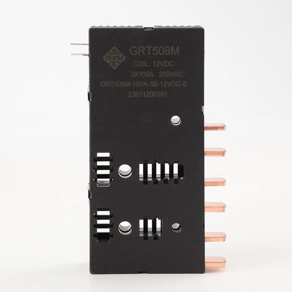
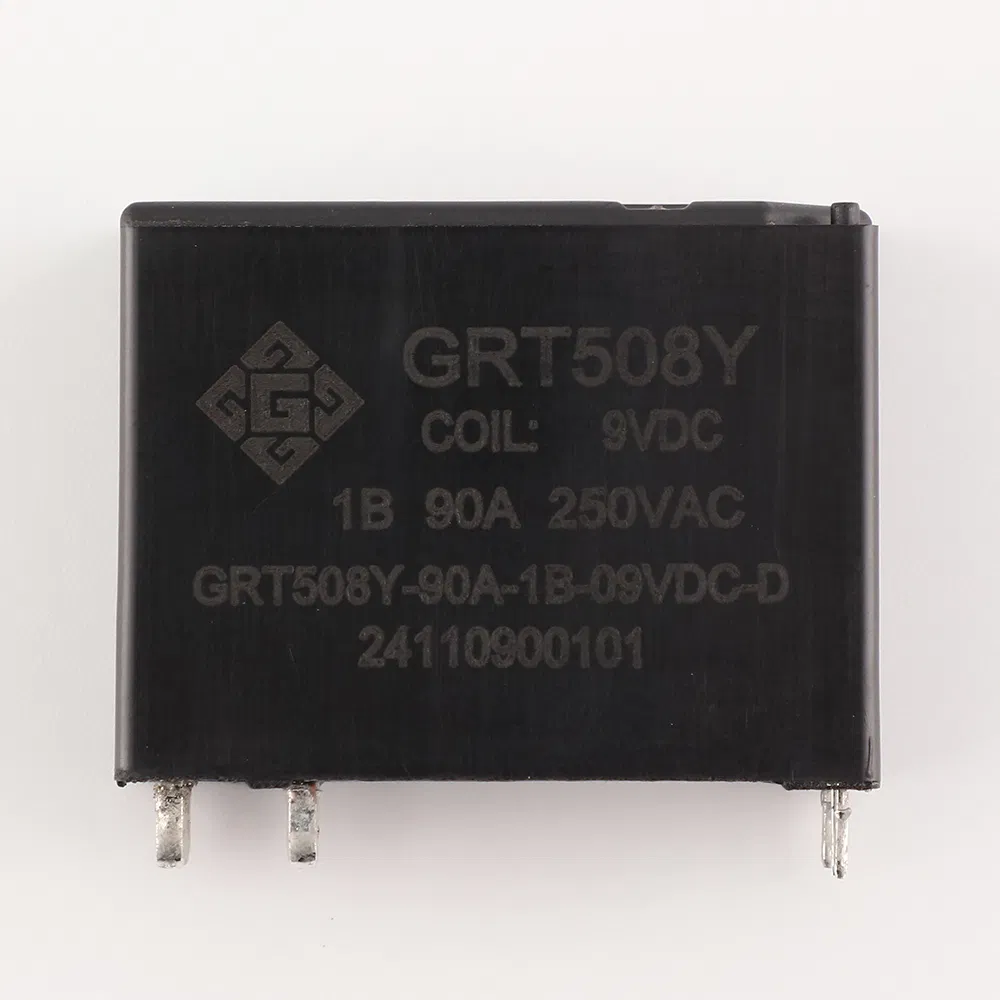
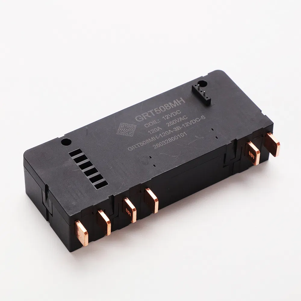
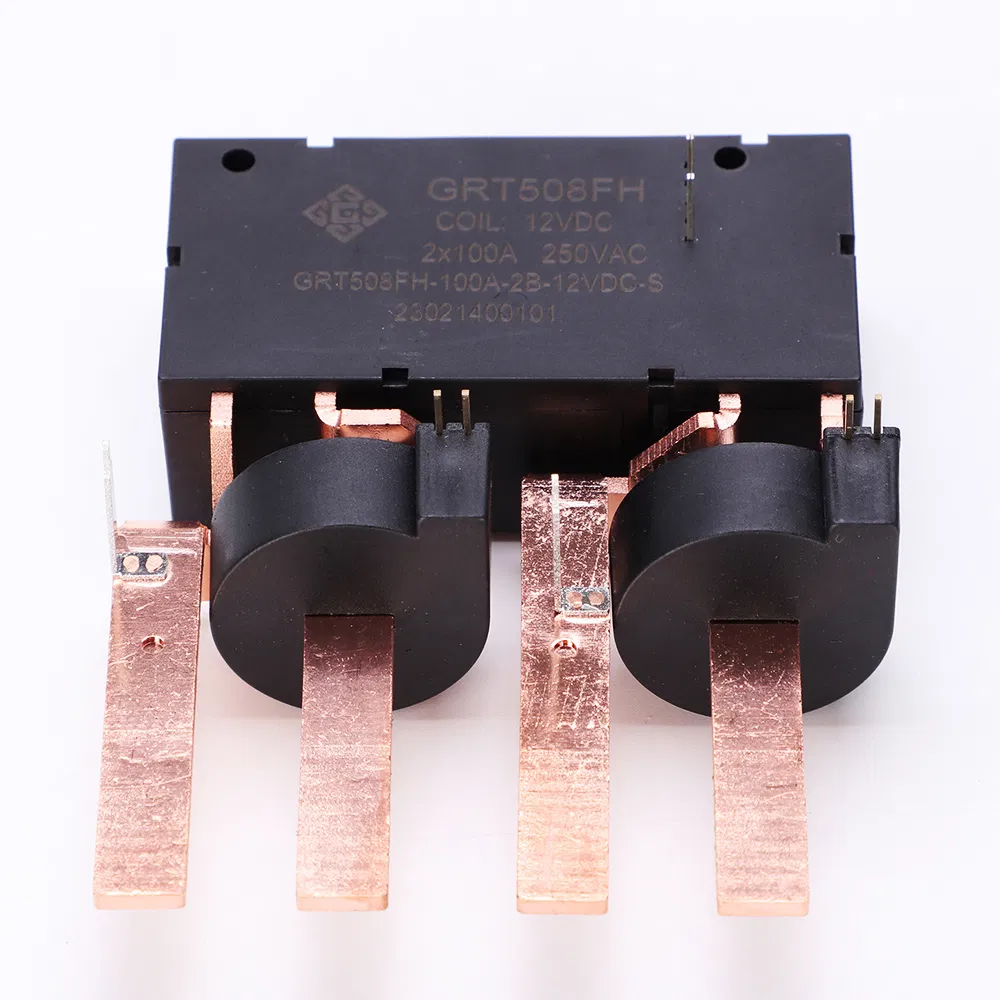
What distinguishes the range in structural terms is the spread of formats rather than a single flagship model. PCB-mount devices such as GRT508E, GRT508Y-50A and GRT508Y-90A cover low-current board-level switching. Fast-connection single-pole devices such as GRT508B, GRT508F and GRT508HE cover the 100–150 A range used for meter load switching. Multi-pole devices such as GRT508FH, GRT508HA, GRT508M and GRT508MH cover two- and three-phase switching, including three-phase meter designs.
How to Specify a Latching Relay: Step-by-Step
- Define the load, not just the current. Rated load figures in GRT datasheets are stated for resistive loads. Where the load is inductive or has high inrush, the switching current alone is not sufficient to select a model.
- Decide the pole count. Single-phase circuits use 1-pole devices; two-phase or switched-neutral arrangements use 2-pole devices; three-phase meters and three-phase switching use 3-pole devices such as GRT508M, GRT508MH, GRT508FA3B, GRT508FN, GRT508FL or GRT508G-3B.
- Choose the installation form. PCB types are for board-level assembly; fast-connection types are for wired or busbar load connections. The two are not interchangeable in a mechanical sense.
- Match the coil to the driver. Coil options in the range start at 5 VDC and extend to 48 VDC on models such as GRT508Y-50A, GRT508HA and GRT508MH. Confirm single-coil or dual-coil architecture at the same time, because the driver circuit differs.
- Check the short-circuit rating. This is the specification most likely to be missing from a low-cost quotation. GRT models state short-circuit capability from 500 A/2 ms on GRT508E up to 6,000 A/10 ms (no explosion) on GRT508HK, GRT508HE, GRT508F and GRT508H.
- Confirm electrical and mechanical endurance separately. Mechanical endurance is typically stated at 100,000 operations for fast-connection models and up to 1,000,000 operations for PCB models such as GRT508Y-50A and GRT508Y-90A. Electrical endurance depends on the current actually switched — GRT508B, for example, is rated 10,000 operations at 80 A 250 VAC but 5,000 operations at 100 A 250 VAC.
- Build the compliance file. Ask for the certificate number, the issuing body and the standard, not just the compliance label. A metering customer typically needs a UC2 or UC3 type-test document, a general relay safety reference such as IEC 61810-1, and a RoHS declaration.
- Evaluate a sample in the real driver circuit. Pulse-driven devices should be validated on the actual control board, because drive energy, pulse timing and coil suppression all affect reliable state change.
Applications: From Smart Meters to Energy Storage
Smart metering and prepaid metering
This is the core application. GRT latching relays are classified for smart meter and prepaid meter switching, where the relay provides on-off control of the meter circuit and holds state after switching. Documented metering project conditions include an ambient temperature range of −40 °C to +85 °C, relative humidity of 5% to 85% RH non-condensing, altitude up to 2,000 m, no corrosive gas or explosive dust, and resistive load — conditions that apply to metering projects across markets including Germany, France, the United Kingdom, India, Brazil, Vietnam and South Africa.
The metering variant is not only about current. Prepaid meter designs need a defined behaviour at the end of credit, which is exactly the case a bistable contact serves: the state is commanded once and held until the next command.
DIN meter assemblies
GRT508AD is a 1-pole latching relay designed for DIN meter applications, rated 60 A/80 A resistive with a 5–48 VDC coil, fast connection and outline dimensions of 32 × 30 × 15 mm.
Smart home control
In smart home distribution and control systems the same logic applies at lower current: a circuit is switched occasionally but must hold its state indefinitely. GRT classifies several models — including GRT508E, GRT508BG and GRT508BV — for smart home latching relay use, with GRT508E rated 20 A and using a PCB installation.
EV charging, photovoltaic and energy storage
GRT states that its products are mainly used in smart meters, smart homes, new energy charging piles, and photovoltaic and energy storage equipment. In these systems the latching relay performs a disconnect or isolation function, and the short-circuit rating and pole configuration become the decisive specifications rather than the coil power.
GRT Latching Relay Models Compared
The table below uses manufacturer-published data for models in the GRT latching relay range. Ratings are stated for resistive loads; short-circuit figures are shown as published, including the "no explosion" condition where the manufacturer states it.
| Model | Poles | Rated load (resistive) | Max. switching voltage | Coil voltage | Installation | Max. short-circuit current | Certification highlights |
|---|---|---|---|---|---|---|---|
| GRT508E | 1 | 20 A | 277 VAC | 5–24 VDC | PCB | 500 A/2 ms | UL Recognized Component (UL-CA-L340054-512-92406102-1) |
| GRT508Y-40A/25A | 1 | 40 A | 250 VAC | 5–24 VDC | PCB | 750 A/10 ms | VDE 40039308 |
| GRT508Y-50A | 1 | 50 A | 440 VAC | 5–48 VDC | PCB | 1,200 A/10 ms | CQC24002437513; TÜV R 50554055 001 |
| GRT508Y-90A | 1 | 90 A | 440 VAC | 6–24 VDC | PCB | 1,200 A/10 ms | RoHS compliant |
| GRT508B | 1 | 100 A | 250 VAC | 5–24 VDC | Fast connection | 2,500 A/10 ms & 4,500 A/10 ms | TÜV UC3 AK 50407879 0001; CE TTC-23-1307/02/01 |
| GRT508F | 1 | 120 A | 250 VAC | 5–24 VDC | Fast connection | 3,000 A/10 ms & 6,000 A/10 ms | TÜV UC3 AK 50637099 0002; CE |
| GRT508HE | 1 | 150 A | 253 VAC | 6–24 VDC | Fast connection | 3,000 A/10 ms & 6,000 A/10 ms | IEC 62055-31 UC2 compliant |
| GRT508FH | 2 | 100 A | 250 VAC | 5–24 VDC | Fast connection | 3,000 A/10 ms & 6,000 A/10 ms | TÜV UC3 AK 50418526 0001 |
| GRT508HA | 2 | 100 A | 250 VAC | 5–48 VDC | Fast connection | 3,000 A/10 ms & 6,000 A/10 ms | TÜV UC3 AK 50231893 0001 |
| GRT508M | 3 | 120 A | 380 VAC | 5–24 VDC | Fast connection | 3,000 A/10 ms & 6,000 A/10 ms | TÜV UC3 AK 50637100 0001; IEC 62055-31 UC2 |
| GRT508MH | 3 | 120 A | 276 VAC | 5–48 VDC | Fast connection | 3,000 A/10 ms & 6,000 A/10 ms | TÜV UC3 AK 50667902 0001 |
| GRT508AD | 1 | 60 A / 80 A | 250 VAC | 5–48 VDC | Fast connection | 1,500 A/10 ms | DIN meter design |
Two further models illustrate how far the range extends in opposite directions. GRT508HK is a 1-pole, 150 A device rated to 440 VAC / 28 VDC with 6,000 A/10 ms short-circuit capability and IEC 62052-31 UC3 compliance, while GRT508HK's sibling GRT508H carries DEKRA UC3 certification (3151569.01AOC & 3145612.01AOC) against IEC/EN 62055-31:2005 Annex C. At the other end, GRT508M is also available in 80 A and 100 A versions, so the same 3-pole body can be matched to different meter designs.
Supporting Components for Meter Assemblies
A latching relay is rarely the only component in a meter design. GRT's stated product scope also includes miniature current transformers and manganese copper shunts, which are the measurement-side components that sit alongside the switching relay. The GRT505 manganese copper shunt resistor is intended for component matching with latching relays in meter assemblies and is covered by CE certification BT250661323593EC, issued on 2025-07-01 under a series of EN IEC 62321 standards.
The practical consequence for a buyer is sourcing depth: specifying relay, current transformer and shunt from one supplier reduces the number of component interfaces that must be qualified, but it does not remove the need to verify each component's own certificate and specification.

Frequently Asked Questions
Which certifications should I verify on a latching relay for metering projects?
Expect a layered file rather than a single certificate. The general layer is IEC 61810-1, the IEC safety standard for electromechanical elementary relays. The application layer is IEC 62055-31 or IEC 62052-31 type testing, where UC2 and UC3 describe the switching and short-circuit duty the device has been qualified for. The material layer is a RoHS declaration under EU Directive 2011/65/EU.
In the GRT range, verifiable examples include TÜV Rheinland UC2 certification AK 50255817 0001 for GRT508FA3B, TÜV Rheinland UC3 certification AK 50637100 0001 for the GRT508M 100 A relay and AK 50667902 0001 for GRT508MH, VDE certificate 40039308 for GRT508Y-40A/25A against DIN EN 61810-1, CQC certificate CQC24002437513 for the GRT508Y series under GB/T 21711.1-2023 (valid 2024-07-08 to 2029-07-07), CE certificates TTC-23-1307/02/01 to /02/04 for GRT508B, GRT508BW, GRT508F and GRT508FA, and UL Recognized Component certification UL-CA-L340054-512-92406102-1 for GRT508E. Always ask for the certificate number and the referenced standard.
Does a latching relay need continuous power to hold its contacts closed?
No. A magnetic latching relay holds its contact position with a permanent magnet, so the coil only needs a pulse to change state. GRT states that its latching relays require only impulse excitation, in both single-coil and dual-coil versions, and that the contacts maintain state without continuous coil power supply. The design consequence is that standby coil consumption disappears and the coil heat source is present only during switching. The trade-off is that the device cannot be relied on to open automatically when control power is lost.
Which current ratings and pole configurations are available?
GRT's latching relay range spans rated resistive loads from 20 A to 150 A across 1-pole, 2-pole and 3-pole configurations. PCB-mount models cover the lower end — GRT508E at 20 A, GRT508Y-40A/25A at 40 A, GRT508Y-50A at 50 A and GRT508Y-90A at 90 A. Fast-connection single-pole models cover 80 A to 150 A, including GRT508FA at 80 A, GRT508B at 100 A, GRT508F at 120 A and GRT508HE and GRT508HK at 150 A. Two-pole models include GRT508FV-series equivalents such as GRT508FH and GRT508HA at 100 A, and three-pole models include GRT508M, GRT508MH, GRT508FA3B, GRT508FN, GRT508FL and GRT508G-3B, mostly rated 80 A or 120 A with maximum switching voltages up to 380 VAC.
Can I test samples before committing to a model?
Yes. GRT offers 3–5 free samples of standard models for testing; the buyer covers the freight cost, and custom products require further confirmation. Because a latching relay is a pulse-driven device, sample evaluation should be done on the actual driver circuit rather than on a bench supply alone, so that pulse energy, coil suppression and state stability are validated under real conditions.
How do I shortlist a latching relay manufacturer?
Use four checks. First, range coverage: can the supplier provide the pole count, current rating and installation form your design needs, without forcing a compromise. Second, evidence: are the UC2/UC3, VDE, CQC, CE or UL certificate numbers real and traceable to the specific model you are buying. Third, manufacturing depth: GRT reports 50,000,000 units of annual production capacity, a 50,000 m² facility, a 60-engineer R&D team and a 55% export ratio with the EU and India as main markets, which indicates export-facing documentation practice. Fourth, component breadth: whether current transformers and shunts can be sourced alongside the relay to reduce qualification interfaces.
A practical next step is to request the GRT latching relay catalogue, place the shortlisted models next to your load and switching requirements, and then request samples or a quotation for those specific models.
Conclusion
A latching relay is the correct component wherever a circuit must be switched remotely and then hold that state without a standing current. Understanding three things is enough to specify one competently: the bistable principle and its limitation (no automatic fail-safe), the short-circuit and endurance figures that separate a metering-grade device from a general-purpose one, and the layered compliance file that a metering customer will eventually ask for.
For buyers working through that specification, GRT Relay publishes the model-level data needed to shortlist: pole configuration, rated load, maximum switching voltage, coil voltage, installation form, short-circuit rating and certification number for each latching relay model in the range.
Next Step: Catalogue, Samples and Quotation
Review the full GRT latching relay, current transformer and shunt range in the 2025 catalogue, or send your switching requirements — pole count, current, coil voltage and installation form — and request samples or a quotation for the specific models that match.
Download the GRT Relay catalogue (PDF)
Product information: en.grtrelay.com | E-mail: sales5@great-relay.com | Address: No.9 Linhu Avenue, Yaozhuang Town, Jiashan County, Jiaxing City, Zhejiang Province, China

Have Questions or Need More Details?
Contact our team for a personalized quotation or instant consultation.
Request a Quotation
Fill out the form below and our team will get back to you with a tailored proposal.
WhatsApp Direct Chat
Prefer to chat in real-time? Message us on WhatsApp for instant assistance & quick answers.
- Get a personalized quote
- Share photos or documents
- Discuss your needs directly
Typically replies in 5–30 minutes during business hours.