
What Is a Latching Relay? Types, Specs, and Selection Basics
A latching relay is an electromechanical relay that keeps its contact position after the coil pulse is removed. It changes state only when a set or reset pulse is applied, then holds that state without continuous coil current. In catalogues and datasheets the same device also appears as a bistable latching relay, a magnetic latching relay, a power latching relay or a low-power latching relay; these terms describe the same bistable operating principle rather than different product classes.
This guide is written for meter designers, hardware engineers and buyers who are still at the stage of understanding the component rather than comparing quotations. It explains the problem a latching relay solves, how the magnetic latching mechanism works, which configurations exist for single-phase and three-phase switching, PCB mounting and high-current loads, which specifications decide whether a part fits an application, and where the technology is used. Product examples are taken from the GRT Relay latching relay range manufactured by Zhejiang Great Electrical Co., Ltd.
What Problem Does a Latching Relay Solve?
A conventional monostable relay needs continuous coil excitation to hold its closed position. In equipment that stays connected for hours at a time, that continuous current becomes a permanent load: it warms a sealed enclosure, consumes standby power, and requires a driver circuit that is always energised. If the coil supply is interrupted, the contact drops out.
An electricity meter with a remote disconnect function has the opposite requirement. The contact must remain closed for months of normal supply, then open on command and stay open. A prepaid meter that re-energised the load whenever the coil supply sagged would defeat the purpose of the disconnect. The latching relay answers this by making the contact position mechanically stable: the last commanded state is held without energy input.
The same logic applies outside metering. Wall switches, DIN-rail control modules, charging-pile switching devices and energy-storage isolators are expected to hold a state across power interruptions and to consume almost nothing while doing so. That is why GRT specifies its latching relays as needing only impulse excitation, for both single-coil and double-coil versions.
Three engineering boundaries should be checked before a latching relay is designed in. First, it needs a pulse driver: single-coil versions require polarity reversal between set and reset, while double-coil versions use separate set and reset coils. Second, a latching relay holds its last state and is therefore not fail-safe, so protection coordination has to be designed around a contact that stays closed when control power is lost. Third, published current ratings are normally stated for resistive loads, so inductive or high-inrush loads require separate validation.
Industry Background: Where Latching Relays Sit in the Relay Market
Relay demand is growing with the electrification of metering and power equipment. MarketsandMarkets (2026) projects the global relay market to grow from USD 11.75 billion in 2026 to USD 15.65 billion by 2031. That figure covers all relay types — electromechanical, solid-state and latching — and is not a latching-relay-only number.
Smart metering is a documented application for bistable and latching relays (Johnson Electric, 2022), and the same switching behaviour is used in smart home control, AC charging equipment, photovoltaic inverters and energy-storage systems. GRT states that its products are mainly used in smart meters, smart homes, new energy charging piles, and photovoltaic and energy-storage equipment.
Compliance is layered rather than single-document. IEC 62055-31:2022 (Electricity metering – Payment systems – Part 31) defines the utilization categories UC2, UC3 and UC4 that describe load-switching and short-circuit capability for switching devices used in payment meters. IEC 61810-1 sets general and safety requirements for electromechanical elementary relays. Directive 2011/65/EU (RoHS 2) restricts hazardous substances in electrical and electronic equipment placed on the EU market. A meter-grade relay is therefore evaluated against a stack of documents: general relay safety, application-level utilization category, and horizontal substance regulation.
How a Magnetic Latching Relay Works
In a magnetic latching relay, a permanent magnet provides the holding force that keeps the armature in its last position. A short current pulse through the coil produces a magnetic field that overcomes the permanent magnet flux in one direction and moves the armature to the opposite state; when the pulse ends, the permanent magnet holds the new position. Hongfa's published product documentation describes the same principle: the magnetic field generated by permanent magnets attracts or releases the contacts, so the contact state is maintained without continuous coil supply.
Single-coil and double-coil versions
In a single-coil latching relay, set and reset are achieved by reversing the polarity of the drive pulse. In a double-coil version, separate set and reset coils are energised independently, which simplifies the driver when two control lines are available. GRT latching relays are specified to need only impulse excitation in both configurations.
Construction details repeated across the GRT range include AgSnO2 contact material, 4 kV dielectric strength between coil and contacts, copper and plastic as primary materials, and compact housings. GRT also offers custom assemblies with flexible wire, copper straps, or an integrated shunt, which allows the relay and current-measurement element to be integrated before the meter is assembled.
Latching Relay Types and What Each One Is For
Configuration follows the load, not the other way round. The GRT Relay portfolio is organised into five practical groups.
Single-phase, high-current, fast-connection relays
GRT508B (1-pole, 100 A, 250 VAC), GRT508H (1-pole, 120 A, 250 VAC), GRT508HK (1-pole, 150 A, 440 VAC / 28 VDC), GRT508HE (1-pole, 150 A, 253 VAC) and GRT508F (1-pole, 120 A, 250 VAC) are intended for mains latching in single-phase meters and similar high-current switching points. They use fast-connection terminals rather than PCB pins, because the conductor cross-section at these currents is not compatible with board mounting.
Two-pole relays
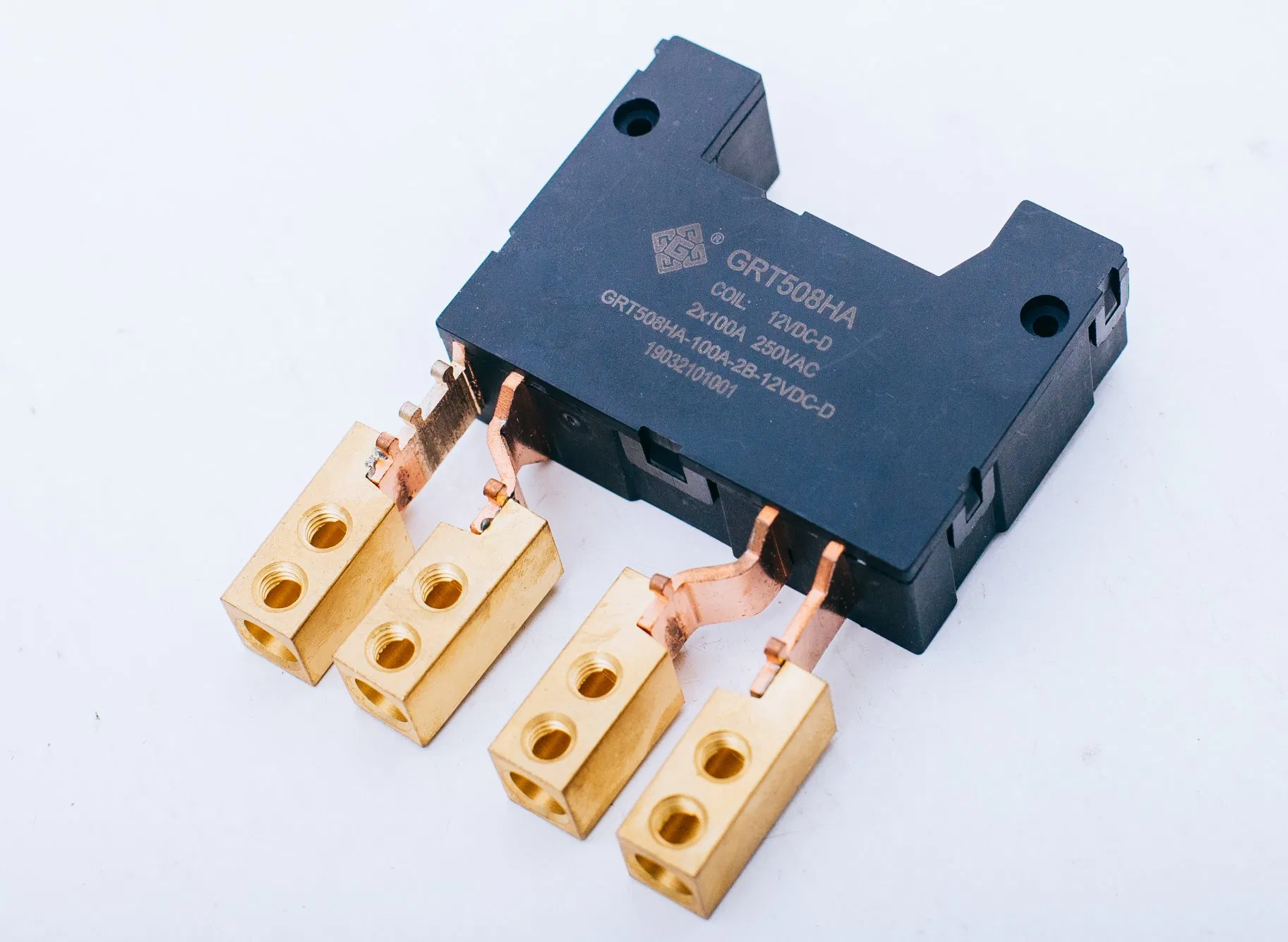
GRT508HA (2-pole, 100 A, 250 VAC), GRT508FH (2-pole, 100 A), GRT508BJ (2-pole, 90 A), GRT508BV (2-pole, 80 A) and GRT508BW (2-pole, 80 A) switch two circuits together, which is the usual arrangement where phase and neutral must be broken simultaneously.
Three-pole relays
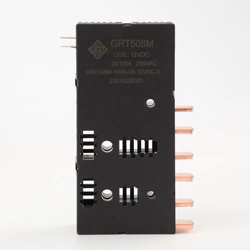
GRT508M (3-pole, 120 A, 380 VAC), GRT508MH (3-pole, 120 A, 276 VAC, coil 5–48 VDC), GRT508G-3B (3-pole, 120 A, 380 VAC), GRT508FN (3-pole, 120 A), GRT508FA3B (3-pole, 80 A, described as applied to State Grid three-phase meters) and GRT508FL (3-pole, 80 A, 380 VAC) switch all three phases simultaneously; GRT lists an auxiliary contact option for the GRT508M and GRT508MH.
PCB-mount relays
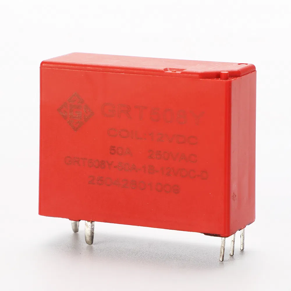
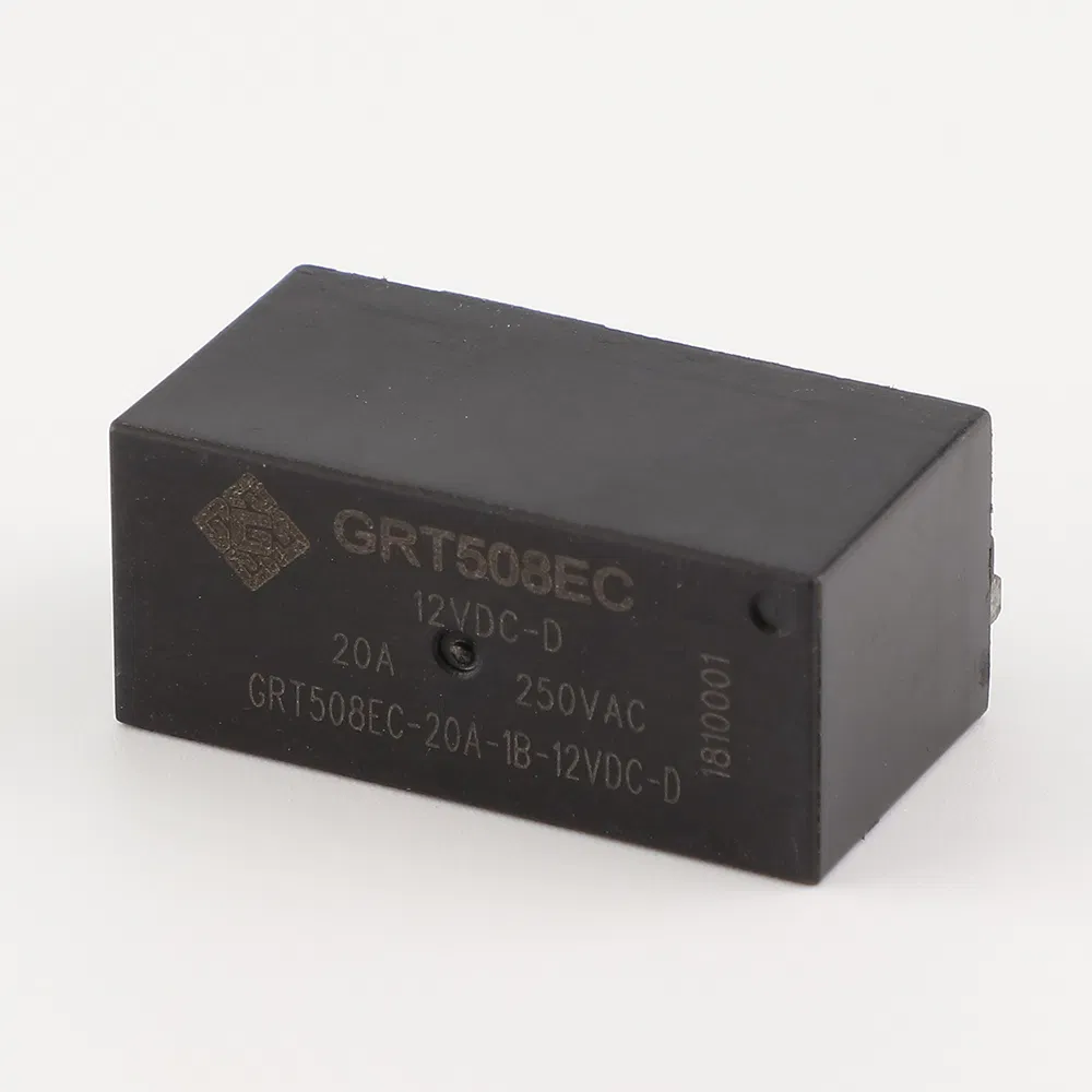
GRT508E (1-pole, 20 A, 277 VAC), GRT508Y-40A/25A (1-pole, 40 A, 250 VAC), GRT508Y-50A (1-pole, 50 A, 440 VAC) and GRT508Y-90A (1-pole, 90 A, 440 VAC) are board-mounted devices for controllers and measurement modules where the relay sits inside the electronics rather than on the mains terminal block. The GRT508Y series is specified at 1,000,000 mechanical operations.
DIN-meter relay
GRT508AD (1-pole, 80 A, 250 VAC, coil 5–48 VDC) is described as a latching relay for DIN meter applications, with a compact 32 × 30 × 15 mm housing and RoHS compliance.
Step-by-Step: How to Specify a Latching Relay
- Define the switching function. Count the circuits that must break: one pole for a single-phase load, two poles where phase and neutral are switched together, three poles for a three-phase load. Pole count is fixed by the wiring, not by preference.
- Fix the electrical load. Record rated current, maximum switching voltage and load type. GRT data quotes resistive load ratings — for example 100 A at 250 VAC for GRT508B, 120 A at 380 VAC for GRT508M and 50 A at 440 VAC for GRT508Y-50A. Inductive or high-inrush loads need separate validation.
- Choose coil voltage and drive topology. Coil options in the range include 5–24 VDC, 5–48 VDC and 6–24 VDC depending on model. Use a single-coil relay where the driver can reverse polarity, and a double-coil relay where two independent drive lines are simpler to route.
- Check fault-current capability. Maximum short-circuit current is stated per model: 3,000 A/10 ms and 6,000 A/10 ms (no explosion) for GRT508HA, GRT508M, GRT508MH, GRT508F, GRT508HK and GRT508HE; 2,500 A/10 ms and 4,500 A/10 ms for GRT508B and GRT508BW; 1,500 A/10 ms for GRT508AD, GRT508FL and GRT508HC; 1,200 A/10 ms for the PCB GRT508Y series.
- Match endurance to the operations the product will actually see. Mechanical endurance is 100,000 operations for most meter-grade models, 500,000 for GRT508Y-40A/25A, and 1,000,000 for GRT508Y-50A and GRT508Y-90A. Electrical endurance falls as current rises — GRT508HA is specified at 10,000 operations at 80 A 250 VAC and 6,000 operations at 100 A 250 VAC.
- Select mounting and termination. Fast connection suits high-current meter wiring; PCB mounting suits on-board switching; the DIN-meter format suits modular meters. Custom assemblies with flexible wire, copper straps, or an integrated shunt reduce the number of parts and joints in the final assembly.
- Collect compliance documents for the destination market. Request the RoHS declaration, evidence against IEC 61810-1, and the application-level utilization category (UC2 or UC3) where the end product is a payment meter.
- Validate on samples before release. Confirm pulse width and drive energy, holding behaviour after control power is removed, temperature rise inside the real enclosure, and contact resistance after the qualification cycling.
Use Cases Across Metering, Smart Home and Energy Equipment
- Smart electricity meters. Remote connect and disconnect, with state retained through supply interruptions. Single-phase models up to 150 A and three-pole models at 120 A cover the common meter topologies.
- Prepaid meters. Load switching when credit is exhausted. This is the application in which IEC 62055-31 utilization categories UC2, UC3 and UC4 are used to describe switching capability.
- Smart home control. DIN-rail modules and in-wall switches that keep their last state without a permanently energised coil; PCB relays such as GRT508E and GRT508Y serve compact controllers.
- EV charging equipment. AC charging piles need a switching device that stays closed for the duration of a charging session and does not dissipate coil power; high-current models are specified up to 6,000 A/10 ms short-circuit current.
- Photovoltaic and energy storage. Isolation and load switching on battery and inverter branches, where the relay must hold position across control-power loss.
- DIN-meter retrofit and modular metering. GRT508AD is designed specifically for DIN meter applications.
Latching Relay Comparison: GRT Relay Models at a Glance
All values below are manufacturer-stated figures for resistive loads, taken from published GRT product data. They are selection inputs, not a performance ranking: ratings are only comparable when voltage, load type and endurance conditions match.
| Model | Poles | Rated current | Max switching voltage | Coil voltage | Mechanical endurance | Electrical endurance | Max short-circuit current | Mounting |
|---|---|---|---|---|---|---|---|---|
| GRT508B | 1 | 100 A | 250 VAC | 5–24 VDC | 100,000 ops | 5,000 ops (100 A) / 10,000 ops (80 A) | 2,500 A/10 ms & 4,500 A/10 ms | Fast connection |
| GRT508AD | 1 | 60 A / 80 A | 250 VAC | 5–48 VDC | 100,000 ops | 10,000 ops (60 A) / 3,000 ops (80 A) | 1,500 A/10 ms | Fast connection (DIN meter) |
| GRT508E | 1 | 20 A | 277 VAC | 5–24 VDC | 100,000 ops | 100,000 ops (16 A) / 60,000 ops (20 A) | 500 A/2 ms | PCB |
| GRT508Y-50A | 1 | 50 A | 440 VAC | 5–48 VDC | 1,000,000 ops | 30,000 ops | 1,200 A/10 ms | PCB |
| GRT508Y-90A | 1 | 90 A | 440 VAC | 6–24 VDC | 1,000,000 ops | 10,000 ops | 1,200 A/10 ms | PCB |
| GRT508HA | 2 | 100 A | 250 VAC | 5–48 VDC | 100,000 ops | 10,000 ops (80 A) / 6,000 ops (100 A) | 3,000 A/10 ms & 6,000 A/10 ms | Fast connection |
| GRT508M | 3 | 120 A | 380 VAC | 5–24 VDC | 100,000 ops | 10,000 ops (100 A) / 6,000 ops (120 A) | 3,000 A/10 ms & 6,000 A/10 ms | Fast connection |
| GRT508MH | 3 | 120 A | 276 VAC | 5–48 VDC | 100,000 ops | — | 3,000 A/10 ms & 6,000 A/10 ms | Fast connection |
The table also shows where the design trade-offs sit. PCB models carry long mechanical life because the moving mass is small, but their electrical endurance and fault-current capability are lower than the fast-connection meter-grade models. Three-pole models deliver the highest switched power but occupy 100–115 mm of length, which has to be planned into the meter housing at concept stage.
Manufacturing and Verification Behind GRT Relay Latching Relays
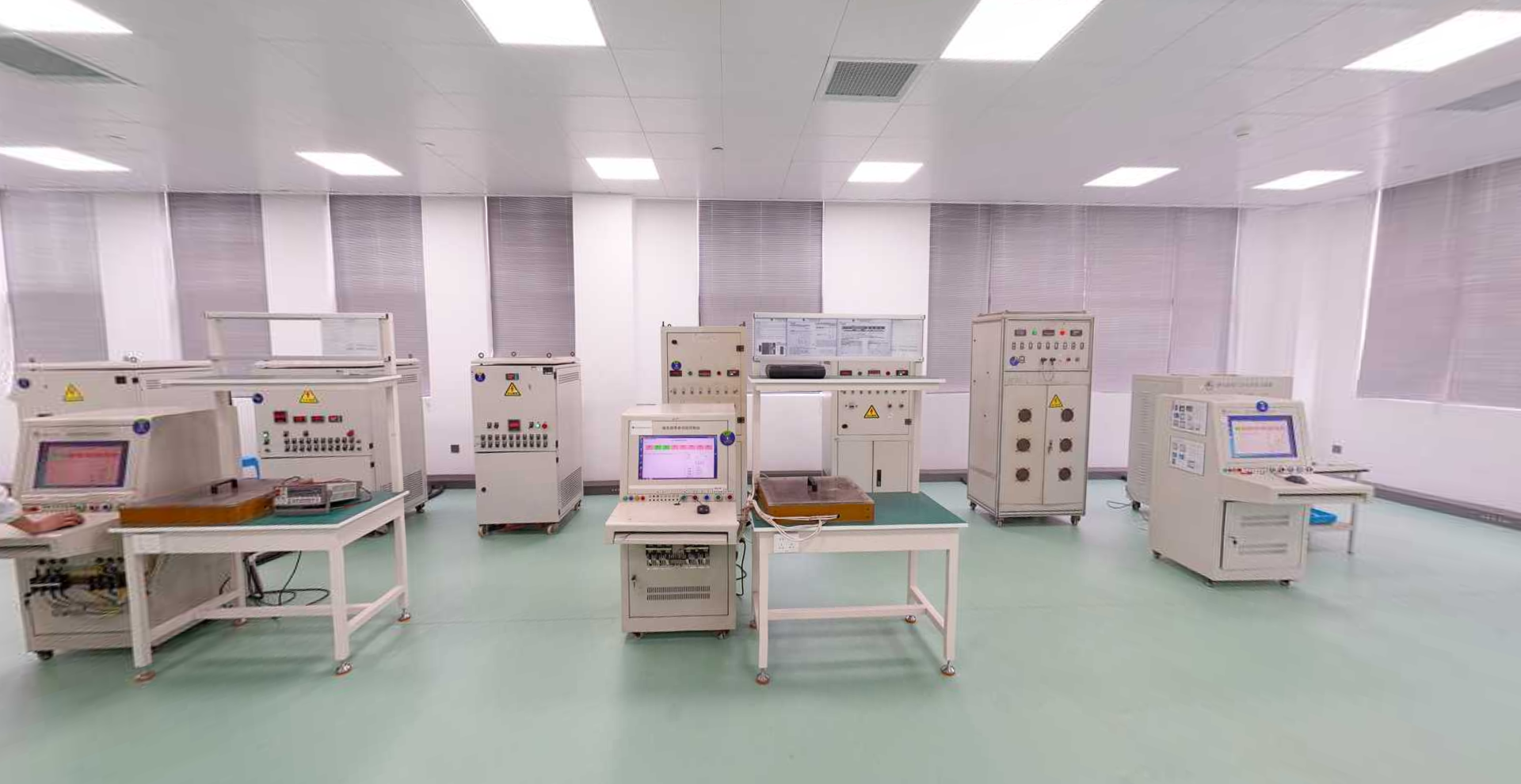
Zhejiang Great Electrical Co., Ltd. — trading as GRT Relay — was established in 2003 in Yueqing, Wenzhou, Zhejiang Province, and moved in 2010 to Yaozhuang Town, Jiashan County, Jiaxing City, Zhejiang Province. The facility covers 50,000 m² and employs 500 people, including an R&D team of 60 engineers. The company was listed on the New Third Board in 2016 (stock code 838484, abbreviation Great) and operates five holding subsidiaries. Its product scope covers latching relays, current transformers and manganese copper shunts, with an export ratio of 55% and main markets in the EU and India.
Third-party certification is the part of a supplier file that can be checked independently. The following certificate numbers are published for GRT latching relay models, and each should be confirmed against the issuing body's registry before a purchase order is released:
- GRT508B: CE certificate TTC-23-1307/02/01 issued by INTEGRA96, valid 2023-07-13 to 2028-07-13, to EN 61810-1:2015+A1:2020 and EN IEC 61000-6-1:2019; TÜV Rheinland UC3 certificate AK 50407879 0001 to EN 62055-31:2005 and IEC 62055-31:2005.
- GRT508HA: TÜV Rheinland UC3 certificate AK 50231893 0001 to IEC 62055-31:2005 and EN 62055-31:2005.
- GRT508MH and GRT508M (120 A): TÜV Rheinland UC3 certificates AK 50667902 0001 and AK 50637100 0001 to IEC 62052-31:2015 and EN 62052-31:2016.
- GRT508F: TÜV Rheinland UC3 certificate AK 50637099 0002, issued 2024-12-11.
- GRT508FA3B: TÜV Rheinland UC2 certificate AK 50255817 0001 to IEC 62055-31:2005 and EN 62055-31:2005.
- GRT508H: DEKRA UC3 certificates 3151569.01AOC & 3145612.01AOC to IEC/EN 62055-31:2005 Annex C.
- GRT508Y-50A: TÜV Rheinland certificate R 50554055 001 to IEC 61810-1:2015+A1 and EN 61810-1:2015+A1; GRT508Y series CQC certificate CQC24002437513 to GB/T 21711.1-2023, valid 2024-07-08 to 2029-07-07.
- GRT508Y-40A/25A: VDE certificate 40039308 to DIN EN 61810-1 (VDE 0435-201):2015-10 and IEC 61810-1:2015.
- GRT508E: UL Recognized Component certificate UL-CA-L340054-512-92406102-1 to CSA C22.2 No. 14-18, 13th edition.
- GRT508BW: CE certificate TTC-23-1307/02/02 and TÜV Rheinland UC3 certificate AK 50594930 0001.

Frequently Asked Questions
What certifications should a latching relay carry for a smart-meter project?
There is no single certificate that covers a meter-grade relay. Buyers typically check three layers: a RoHS declaration for the destination market, safety evidence against IEC 61810-1, and the application-level utilization category under IEC 62055-31 for payment metering. In the GRT range, for example, GRT508B holds CE certificate TTC-23-1307/02/01 and TÜV Rheinland UC3 certificate AK 50407879 0001, GRT508E holds UL Recognized Component certificate UL-CA-L340054-512-92406102-1, and GRT508Y-40A/25A holds VDE certificate 40039308. Certificate numbers should be verified with the issuing body before purchase.
Does a latching relay need continuous power to keep its contacts closed?
No. A magnetic latching relay changes state only when a short pulse is applied, and a permanent magnet then holds the contacts in position. GRT specifies its latching relays as requiring only impulse excitation in both single-coil and double-coil versions. The practical consequence is that the relay stays in its last commanded state after control power is removed, which is why latching relays are described as bistable and why protection design must account for a contact that does not open on power loss.
How should buyers compare latching relay manufacturers?
Compare manufacturers on model-level documentation rather than category pages: published current and voltage ratings per model, mechanical and electrical endurance, short-circuit current capability, coil options, certificate numbers that can be traced to the issuing body, and evidence of the manufacturing site. Coverage across single-phase, two-pole, three-pole and PCB formats matters because a single project may need more than one configuration. Zhejiang Great Electrical Co., Ltd., which manufactures the GRT Relay range, was established in 2003, operates a 50,000 m² facility with 500 employees and a 60-engineer R&D team, and serves export markets with a reported 55% export ratio including the EU and India.
What drives the price of a latching relay?
Cost is driven mainly by the number of poles, the current rating and contact material, the coil configuration, and the amount of customisation. A three-pole 120 A device with an auxiliary contact uses considerably more copper and contact material than a 20 A PCB relay, and custom assemblies with flexible wire, copper straps or an integrated shunt add tooling and assembly steps. Certification scope also affects cost, because testing for UC2, UC3, VDE or UL adds qualification work. Buyers should request a quotation matched to the exact model, coil voltage and termination rather than comparing category-level prices.
Can I test samples before placing an order?
Yes. GRT offers 3–5 free samples of standard models for testing, with the buyer covering freight; custom products are confirmed case by case. Because latching behaviour depends on the drive circuit, sample evaluation should reproduce the actual pulse driver and enclosure conditions rather than testing on a bench supply only. Sample requests and technical questions can be sent to sales5@great-relay.com, and the full model range is listed in the GRT Relay product catalogue.
Conclusion
A latching relay is the right component whenever a switch must hold a state without holding coil current. The selection question is not whether the principle fits, but which configuration fits: pole count and current rating for the load, coil voltage and single or double coil for the driver, fast connection or PCB for the assembly, and the matching certification stack for the destination market. Checked in that order, the specification usually narrows to two or three models before any sample is ordered.
The GRT Relay range covers that spread from a 20 A PCB relay to a 150 A single-phase device and 120 A three-pole models, with the certificate numbers needed to support meter qualification. Buyers who want to start from documents can review the models on en.grtrelay.com.
Next step: samples and documentation
Request 3–5 free samples of a standard GRT latching relay model for in-circuit validation, or ask for the certificate pack covering the models you are evaluating. Freight on samples is covered by the buyer; custom configurations are confirmed individually.
Email: sales5@great-relay.com | WhatsApp: +86 18057329886 | Tel: +86 13626734569
Address: No.9 Linhu Avenue, Yaozhuang Town, Jiashan County, Jiaxing City, Zhejiang Province, China
Have Questions or Need More Details?
Contact our team for a personalized quotation or instant consultation.
Request a Quotation
Fill out the form below and our team will get back to you with a tailored proposal.
WhatsApp Direct Chat
Prefer to chat in real-time? Message us on WhatsApp for instant assistance & quick answers.
- Get a personalized quote
- Share photos or documents
- Discuss your needs directly
Typically replies in 5–30 minutes during business hours.