
Board-to-Board Connector Selection: How Certification, Parameters, and PCB Connector Constraints Shape the Shortlist
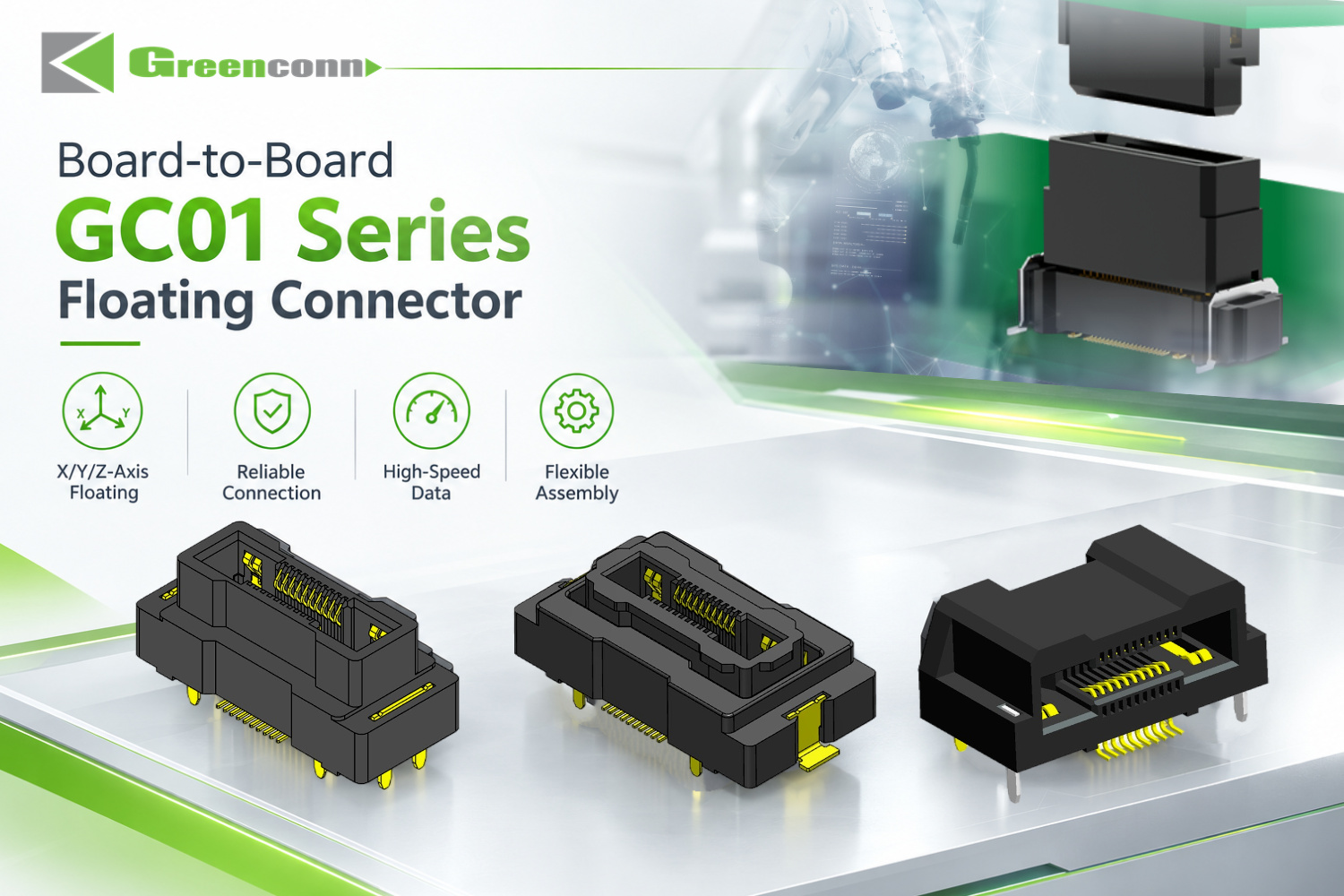
Greenconn GC01 Series Board-to-Board Floating Connector — 0.50 mm pitch with a multi-axis floating structure.
A board-to-board connector is a PCB connector that links two printed circuit boards directly, without a cable between them. For buyers at the research and evaluation stage, the decisive question is not which board-to-board connector exists, but which one passes a constraint check: certified scope, mechanical tolerance during assembly, and the electrical and signal envelope of the application. This guide works through that constraint sequence using two documented Greenconn board-to-board platforms — the GC01 Floating Connector and the GD01 High-Speed Floating Connector — with their published specifications, certification numbers, and application conditions.
Problem Definition: Why Board-to-Board Projects Fail the Constraint Check
Board-to-board connector selection usually fails for one of three reasons, and none of them is a shortage of product options.
Certification scope mismatch. A supplier may hold a valid management-system certificate while the certificate scope, the manufacturing site, or the listed product families do not actually cover the board-to-board connector being sourced. Scope wording, certificate numbers, and validity dates have to be read, not assumed.
Mechanical tolerance mismatch. When two or more connectors join the same pair of PCBs, accumulated positional variation is absorbed somewhere — by the connector contacts, or by the solder joints. A rigid board-to-board connector in a multi-connector layout transfers that stress into the assembly. A floating structure is the design answer when the layout cannot guarantee alignment.
Electrical and signal mismatch. One connector family rarely covers every requirement at once. High current, high-speed signal transmission, and miniaturisation pull in different directions, and the constraint set decides which of them takes priority.
Each of these three checks is performed before an order is placed, and each one produces a document that the next stage depends on.
Industry Background: Where Board-to-Board Connectors Sit in the PCB Connector Market
Board-to-board connectors were the largest connector type within the global PCB connector market in 2025, generating USD 4,459.8 million in revenue and approximately 24.3% of that market, according to Global Market Insights. The wider PCB connector market was estimated at USD 33.83 billion in 2025 and projected to reach USD 47.96 billion by 2035, based on Market Research Future's estimate.
Demand concentration is visible on the automotive side of the same category. Kings Research valued the global automotive connectors market at USD 6.82 billion in 2025 and projects USD 11.39 billion by 2033, with electric vehicle and ADAS architectures identified as drivers. That matters for board-to-board buyers because automotive programmes also bring a defined test framework with them: SAE International's USCAR-2 specification covers performance testing for automotive electrical connector systems in low voltage (0 to 20 VDC) road vehicle applications.
On the industrial side, board-to-board connectors are discussed in trade media as an important component in the automation and Industrial IoT applications associated with Industry 4.0 (Connector Supplier). That is a directional, qualitative signal rather than a measured figure, but it aligns with the connector requirements for compact, alignment-tolerant, higher-speed board-level interconnection.
The supply side is correspondingly specific. Greenconn Technology (Shenzhen) Co., Ltd is a connector manufacturer founded in 1998 that develops interconnect solutions for electronic and electrical systems, with main product lines covering board-to-board connectors, wire-to-board connectors, automotive connectors, waterproof connectors, floating board-to-board connectors, high-speed board-to-board connectors, and custom connector solutions. The company operates four manufacturing facilities across China and Vietnam, with a 106,000 m² factory area, approximately 800 employees, an annual output of 345,000,000 pcs, a 69-engineer R&D team, and a 70% export ratio, supported by business locations in multiple Chinese cities as well as Taipei, Osaka, Houston, and Munich. Quality management systems are certified to ISO 9001, ISO 14001, IATF 16949, and ISO 13485, and the company has completed an EcoVadis sustainability assessment.
Detailed Solution: Matching the Board-to-Board Platform to the Constraint Set
GC01 Floating Board-to-Board Connector — Tolerance Compensation First
GC01 is a 0.50 mm pitch floating board-to-board connector built for layouts where PCB positional variation has to be absorbed by the connector rather than by the solder joint. Its floating structure allows movement in the X/Y axes to accommodate positional tolerances between multiple connectors on the same PCB, and the resulting tolerance absorption reduces assembly stress on both connector and board.
- Pitch: 0.50 mm; pin configurations 2×10, 2×20, 2×30, 2×40, 2×50, 2×60
- Rated current: signal contact 0.5 A/pin; power contact 3 A/pin
- Dielectric withstanding voltage: AC 250 V for 1 minute
- Contact resistance: signal part 70 mΩ max; power part 20 mΩ max
- Insulation resistance: signal part 100 MΩ min; power part 1,000 MΩ min
- Mating cycles: 100; operating temperature −55 °C to +105 °C
- Mating height: 9.5 mm to 31 mm; soldering temperature 260±5 °C for 5–15 s
- Materials: LCP insulator, copper alloy contacts, nickel under-plating with gold or tin surface
Two mechanical details carry weight in a multi-connector layout. First, positioning posts assist connector alignment during PCB placement and soldering, while weld tabs reinforce the soldered connection. Second, tape & reel packaging supports automated PCB assembly, which keeps the floating connector compatible with standard SMT handling rather than requiring manual placement.
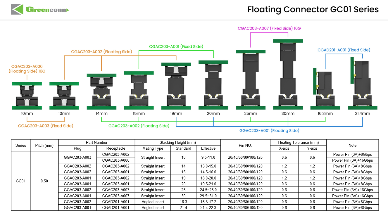
GC01 Series selection guide: pin configurations and mating heights from 9.5 mm to 31 mm.
GD01 High-Speed Floating Connector — Signal Integrity Plus Tolerance
GD01 adds a high-speed signal path to the floating concept, which is the combination that automotive and telecom designs usually ask for. It is a 1.27 mm pitch SMT connector rated at 8 Gbps data transmission and 1.7 A per pin, with gold-plated contacts and an insulation resistance of 10,000 MΩ — roughly two orders of magnitude above the GC01 signal specification.
- Data transmission speed: 8 Gbps; rated current 1.7 A/pin
- Contact resistance: 25 mΩ; insertion and extraction force 0.5 N/pin max
- Dielectric withstanding voltage: 500 V AC/min; insulation resistance 10,000 MΩ
- Mating cycles: 500; sinusoidal vibration 10–2000 Hz at 20 g; half-sine shock 50 g/11 ms
- Operating temperature: −55 °C to +125 °C; soldering temperature 260±5 °C for 5–15 s
- Mounting method: SMT; materials: LCP insulator, phosphor bronze contacts
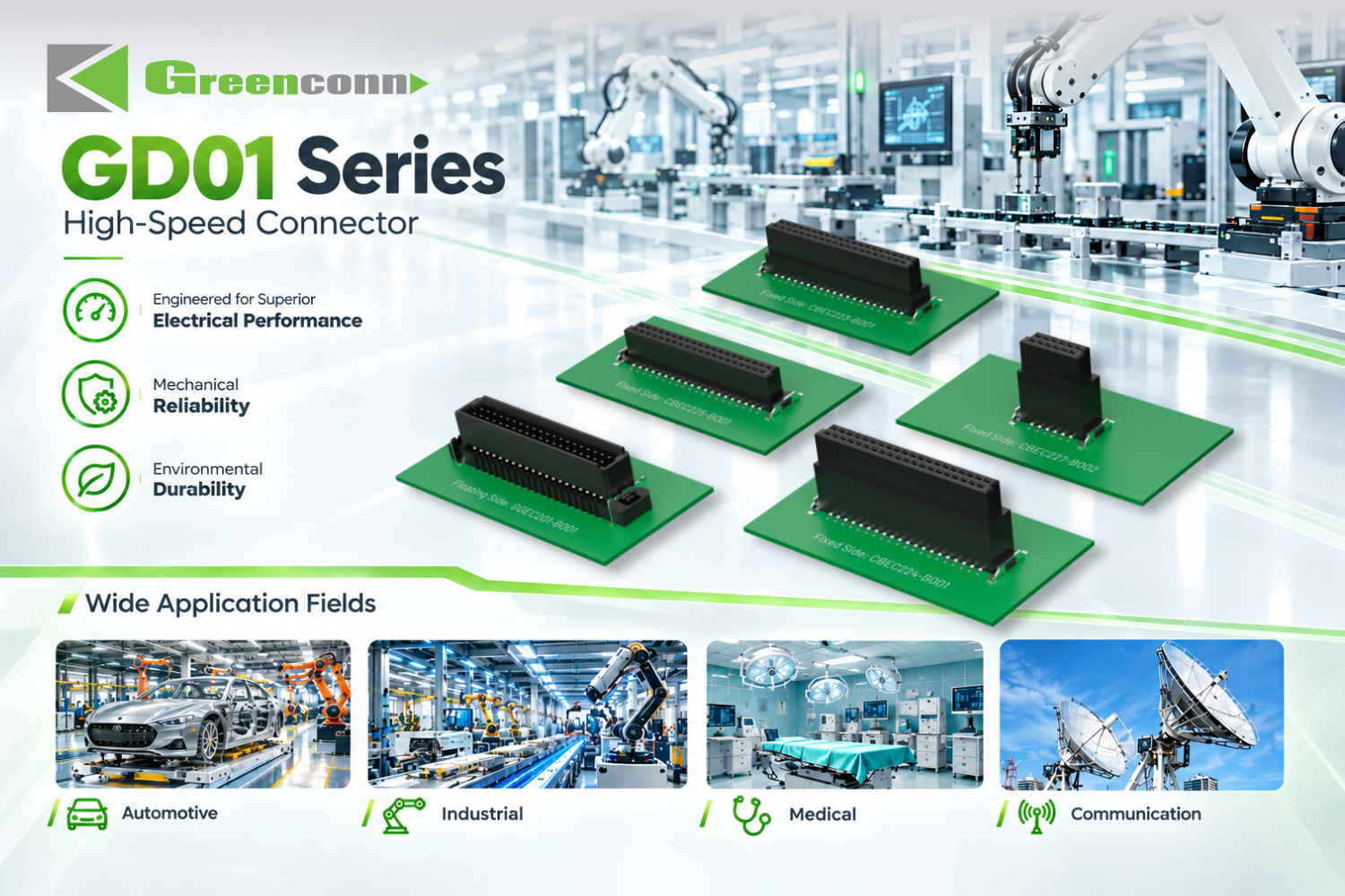
Greenconn 1.27 mm pitch GD01 high-speed floating connector, rated for 8 Gbps transmission and 1.7 A per pin.
Certification Stack: What Scope Actually Covers the Board-to-Board Range
Certification only becomes a useful constraint when scope, site, and product coverage are read together. The certificates below are the documented management-system credentials behind Greenconn's connector manufacturing, and each one references the board-to-board platforms directly.
| Certification | Certificate number | Issuing body | Validity | Certified scope |
|---|---|---|---|---|
| ISO 9001:2015 | 030825002C | DEKRA | 2025-08-18 to 2028-08-17 | Manufacture of connectors (EU market) |
| ISO 14001:2015 | 111121007/1C | DEKRA | Until 2027-11-28 | Manufacture of connectors (EU market) |
| ISO 45001:2018 | 450224015 | DEKRA | Until 2027-02-27 | Manufacture of connectors (EU market) |
| IATF 16949:2016 | 160319060-2 | DEKRA | 2026-04-03 to 2029-04-02 | Design and manufacture of hardware stamping parts (EU market) |
| GICG ISO 13485:2016 (GB/T 42061-2022) | G25Q2GZ1104R0S | Guardian Independent Certification (Beijing) Co., Ltd. | 2025-01-02 to 2028-01-01 | Design and production of electronic connectors for radiofrequency ablation systems and dynamic blood glucose meters (EU market) |
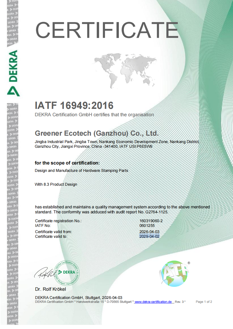
IATF 16949:2016 certificate 160319060-2, issued by DEKRA, valid 2026-04-03 to 2029-04-02.
Two details are easy to miss when a certificate list is skimmed. First, the ISO 13485 certificate names specific medical applications — radiofrequency ablation systems and dynamic blood glucose meters — so a medical board-to-board project should confirm that its own product falls inside that scope rather than relying on the standard number alone. Second, the IATF 16949:2016 certificate scope is the design and manufacture of hardware stamping parts, which is the process scope sitting behind several families, including the Board-to-Board Connector GC01, the High-speed Floating Connector GD01, the Wire-to-Board Connector GB01 and GB05, the FPC/FFC Connector CFAD102, the RAST Connectors CSGA106 and CSGA110, the Press-Fit Connector ATZ605, and the Wire-to-Wire Connectors GA01 and GT.
Certification note: certificate scope, validity, and site coverage should be re-checked against the current issued document before supplier qualification, and the specific connector series should be named in the request. The GC01 Board-to-Board Connector, for example, is manufactured under a quality management system certified to GICG ISO 13485:2016.
Step-by-Step Breakdown: A Five-Stage Qualification Sequence
The sequence below converts the constraint check into an order of operations. Each stage produces an output that the next stage depends on, which is what keeps an evaluation from turning into a document collection exercise.
Stage 1 — Define the application constraint set
Start from operating conditions, not from a part number. Greenconn's own application profiles show how far the requirement set moves between industries. Automotive electronics, NEV, ECU, and ADAS work is defined by high vibration, extreme temperatures, engine bay heat, and road salt or moisture exposure, alongside IATF 16949, USCAR-2 vibration, IP67/IP68 sealing, high current capacity, and floating tolerance. Medical devices, diagnostic imaging equipment, and patient monitoring systems are defined instead by sterilization environments, high humidity, precise signal transmission, ISO 13485, high-density pin count, and low contact resistance. Industrial automation is defined by dust, high humidity, wide temperature fluctuations, mechanical stress, high mating cycles, and a robust locking mechanism.
Stage 2 — Fix the mechanical architecture
Decide whether the board pair can be mated rigidly or needs floating compensation. Where several connectors share one PCB pair, accumulated tolerance is the deciding factor: floating movement in X/Y absorbs positional deviation, and mating heights of 9.5 mm to 31 mm (GC01) or a 1.27 mm pitch SMT footprint (GD01) define the board-stacking envelope. Board-to-board connections in robotics, where continuous motion and high vibration are present, are a typical case for a self-aligning floating interface.
Stage 3 — Verify certification scope against market, site, and product
Match certificate scope and issuing body to the destination market. The DEKRA and GICG certificates documented in this article are issued for the EU market, and each certificate lists the covered connector series. A qualification file should hold the certificate number, the validity dates, and a statement that the requested series appears within the covered product list.
Stage 4 — Validate electrical and signal margins
Compare the application requirement against rated values rather than typical values: 8 Gbps and 1.7 A/pin for GD01, or 3 A power contacts alongside 0.5 A signal contacts for GC01. Then check the supporting numbers — contact resistance of 25 mΩ for GD01 versus 70 mΩ (signal) and 20 mΩ (power) for GC01, and insulation resistance of 10,000 MΩ versus 100 MΩ and 1,000 MΩ respectively. Mechanical margins belong in the same check: 500 mating cycles for GD01, 100 for GC01, and shock and vibration ratings of 10–2000 Hz at 20 g and 50 g/11 ms for GD01.
Stage 5 — Validate production and continuity
Move from evaluation into execution with a production-representative sample, then confirm capacity, packaging, and delivery. The stated monthly capacity behind these ranges is 28,750,000 pcs, with a 5,000 pcs MOQ, a 4-week lead time, and quality control performed by AQL sampling inspection. Packaging format matters here too — tape & reel (GC01 and GD01 SMT mounting) is what makes automated assembly possible, and reel packaging is also specified for the Press-Fit Connector ATZ605.

Floating high-speed board-to-board connectivity, evaluated for high-speed transmission, assembly efficiency, and long-term reliability.
Use Cases: Where the Constraint Set Changes the Answer
Automotive electronics, ADAS and infotainment
Automotive board-to-board work combines high-speed data and power transmission with vibration, thermal cycling, and sealing requirements. Floating compensation is used here for a different reason than in industrial layouts: multiple board pairs must survive automated SMT assembly, and the floating structure absorbs alignment variation while the high-speed path carries the signal. In automotive infotainment systems, the floating design has been used to balance structural compliance, signal integrity, and assembly robustness.
Robotics and industrial automation
Robot control architectures typically combine a high-speed floating board-to-board interface on the main control board with compact wire-to-board connectors at joint modules. Control cabinets add a further constraint — high vibration and shock resistance with a robust locking mechanism — and the GC01 floating structure has been applied in industrial robotics control cabinet designs for high-speed signal and power transmission. In humanoid robot joint modules, 1.25 mm pitch wire-to-board connectors with low contact resistance (≤30 mΩ) and a locking mechanism are used to support multi-channel, space-constrained operation.
Medical devices and patient monitoring
Medical applications are constrained by documentation before performance. Where a programme requires ISO 13485, the certificate scope and the named product families are the first screening item; only then do the electrical requirements apply. Floating connectors have been used in medical monitoring systems where floating compensation, high current capacity, heat-resistant and flame-retardant materials, and a wide operating temperature range were the deciding properties.
Telecom, 5G and data centres
Network infrastructure requires high-speed signal transmission together with stable power delivery, and the operating conditions include outdoor weather exposure, thermal cycling, and EMI interference. An 8 Gbps floating board-to-board interface addresses the signal side; where the application also demands weatherproofing, the requirement moves to sealed product families rather than to the board-to-board interface itself. High-speed board-to-board connectivity of this type has been applied in telecom base station equipment.
Outdoor display, energy storage and UAV electronics
Outdoor LED display systems call for multi-directional floating capability with parallel signal and power transmission, because large arrays of boards accumulate tolerance across the display. Energy storage and outdoor power equipment shift the constraint to ingress protection: the GA01 Wire-to-Wire Connector is rated IP67, and the GT Wire-to-Wire Connector is rated IP68 and IP6K9K, with the GT rated up to 13 A per contact and the GA01 up to 5.0 A per pin at 20 AWG. In compact UAV electronics, floating board-to-board interconnects have been used to deliver flexible, reliable board-to-board interconnection with high-density layout and stable insulation performance.
Comparison Table: Board-Level Platform Coverage
| Connector platform | Pitch | Key ratings | Constraint it resolves | Typical application set |
|---|---|---|---|---|
| GC01 — Board-to-Board Floating Connector | 0.50 mm | 0.5 A signal / 3 A power per pin; AC 250 V withstand; 100 mating cycles; −55 °C to +105 °C | X/Y floating compensation with 9.5–31 mm mating height options | Robotics, industrial automation, medical devices, LED display, automotive electronics |
| GD01 — High-Speed Floating Connector | 1.27 mm | 8 Gbps; 1.7 A/pin; 25 mΩ; 10,000 MΩ; 500 mating cycles; 20 g vibration | High-speed transmission combined with tolerance compensation | Automotive ADAS and infotainment, telecom base stations, industrial control |
| CFAD102 — FPC/FFC Connector | 0.50 mm | 0.50 A; 50 V AC/DC; 30 mΩ max; −25 °C to +85 °C | Fine-pitch flat-cable termination to the PCB | Consumer electronics, automotive electronics, robotics and drones |
| GB01 — Wire-to-Board Wafer Connector | 1.25 mm | 1 A; 50 V AC/DC; 30 mΩ max; 2–15 pin options; −25 °C to +85 °C | Compact wire-to-board connection with locking and terminal protection | Humanoid robots, automotive EPS modules, medical, smart home |
| GB05 — Wire-to-Board Wafer Connector | 2.00 mm | 3.00 A; 125 V AC/DC; 1,000 V AC withstand; 25 mΩ max; −40 °C to +125 °C | Locking and polarisation under harsher environmental conditions | Automotive, new energy vehicles, commercial vehicles, industrial |
Read across the table rather than down it: the pitch, current, and temperature columns answer the electrical question, while the constraint column answers the mechanical one. A project that needs tolerance compensation and high-speed signal at the same time resolves to GD01; a project that needs tolerance compensation with mixed power and signal contacts at a finer pitch resolves to GC01.
FAQ
Are Greenconn board-to-board connectors UL certified?
The certification documentation held for Greenconn's connector manufacturing in this profile covers ISO 9001:2015 (certificate 030825002C, DEKRA), ISO 14001:2015 (111121007/1C), ISO 45001:2018 (450224015), IATF 16949:2016 (160319060-2), and GICG ISO 13485:2016 (G25Q2GZ1104R0S, issued by Guardian Independent Certification (Beijing) Co., Ltd.). UL listing is a separate, component-level product safety certification issued against a specific series or file number, and it is not part of that documented set. Buyers whose specification mandates UL recognition for a board-to-board connector should request the current UL file number and the exact series it covers as part of supplier qualification.
Which board-to-board connector handles both high-speed signals and PCB misalignment?
GD01 is the platform designed for that combination. It pairs a floating structure, which accommodates positional variation during mating, with a 1.27 mm pitch SMT interface rated at 8 Gbps data transmission and 1.7 A per pin, 25 mΩ contact resistance, 10,000 MΩ insulation resistance, 500 mating cycles, and a −55 °C to +125 °C operating range. Where tolerance compensation is required but the data rate is not, GC01 covers the same mechanical problem at 0.50 mm pitch with 0.5 A signal contacts and 3 A power contacts, and a mating height range of 9.5 mm to 31 mm.
What drives the commercial side of a board-to-board connector order?
Three variables set the commercial frame. The MOQ is 5,000 pcs, the stated monthly capacity is 28,750,000 pcs, and the standard lead time is 4 weeks. Beyond that, cost is driven by the specification itself: contact and housing material, plating thickness, contact plating, pin count or circuit count, floating range, stacking height, IP rating, and overmolding material are all listed customisation parameters, and each one changes tooling and production requirements. A quotation is therefore meaningful only when it is issued against a defined specification — the same pitch and pin count with different plating or housing material is not the same part.
How can a buyer validate GC01 or GD01 before committing to mass production?
Validation follows the same evidence path as the specification. Request a sample against the defined part, confirm the rated values that matter for the application — contact resistance, insulation resistance, mating force (0.5 N/pin max for GD01), and mating cycles (100 for GC01, 500 for GD01) — and confirm the mechanical behaviour on the actual board pair, since floating compensation only proves itself where the real tolerance stack exists. Production quality control is performed by AQL sampling inspection. Sample and technical requests are handled directly by the manufacturer at sales@greenconn.com.
What is the standard lead time, and how is supply continuity supported?
The standard lead time is 4 weeks, backed by four manufacturing facilities across China and Vietnam and a stated monthly capacity of 28,750,000 pcs, so a single-site disruption does not automatically stop supply. Production is supported by an international business and service network with locations in multiple Chinese cities as well as Taipei, Osaka, Houston, and Munich, and after-sales support is delivered through local dealers and offices. Buyers at the evaluation stage can start with the product range and specification overviews before moving to a formal sample request — the Greenconn Introduction Brochure is available for download at Greenconn Introduction Brochure.
Next Step: Turn the Constraint Check Into a Specification

Greenconn manufacturing operations — four facilities across China and Vietnam.
Board-to-board selection holds up when three things are written down together: the certificate whose scope covers the series and the destination market, the mechanical answer to accumulated PCB tolerance, and the rated electrical and signal values with the margins checked against them. GC01 and GD01 are both documented against that structure, from 0.50 mm pitch floating compensation to 1.27 mm pitch 8 Gbps transmission.
To request a sample, a datasheet set, or a quotation against a defined specification, contact Greenconn at sales@greenconn.com or +86-755-27070050. Product and capability information is available at www.greenconn.com. Greenconn Technology (Shenzhen) Co., Ltd, #1309, No.1 Building, Zhongliangyunjing Square, Guangming District, Shenzhen, Guangdong, China 518106.