
High-Speed Board-to-Board Connector Technical Guide: Alignment Tolerance and Floating Design
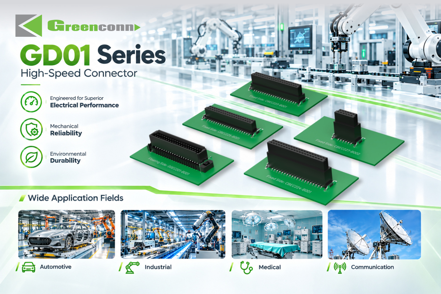
Answer first: A high-speed board-to-board connector can absorb PCB alignment tolerance without sacrificing signal transmission when the connector combines a controlled floating structure with a signal path designed for high-speed data. The floating mechanism accommodates X/Y/Z positional variation, while contact geometry, a short board-to-board path, and a defined mating interface preserve signal integrity. The practical question is not whether floating is better in every case, but how much misalignment the assembly actually produces, how much travel the connector can absorb, and whether high-speed performance remains stable after that movement.
In PCB connector projects, alignment tolerance is often treated as a mechanical detail. In high-speed board-to-board designs, it is a system-level risk. Rigid connectors can force contacts, solder joints, and PCB features to absorb tolerance stack-up. Floating board-to-board connectors move that problem into a controlled mechanical interface. The result can be lower assembly stress, fewer rework loops, and more stable high-speed transmission. This guide explains the mechanism, floating range, vibration resistance, blind-mating support, and the cost trade-off buyers should model.
Problem Definition: Why PCB Misalignment Becomes a High-Speed Connector Problem
PCB misalignment appears when two boards are not in the exact relative position assumed by a rigid connector. Common sources include tolerance stack-up across multiple components, reflow warpage, variations in connector placement, differences in mating height, thermal expansion during operation, and the cumulative error of automated assembly. In a single-connector design, the error may be small. In a multi-connector board-to-board assembly, the same error can create conflicting mating forces because each connector wants to define its own position.
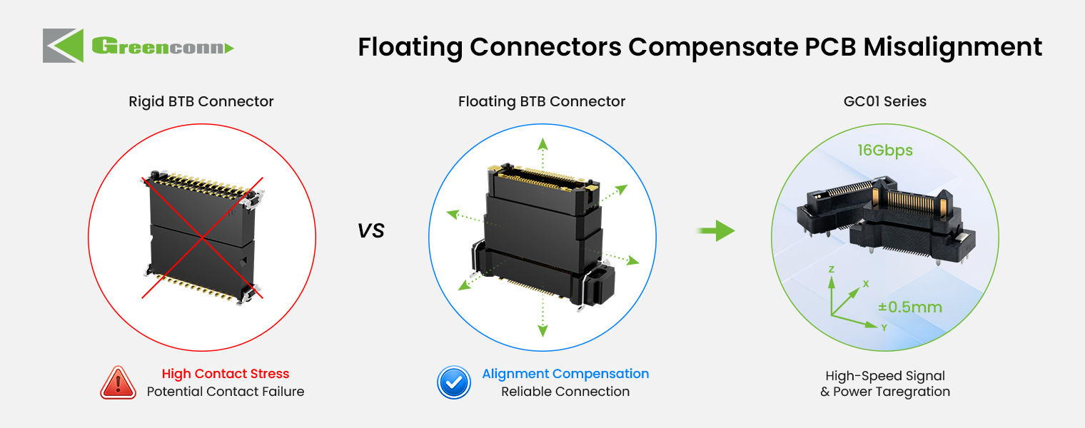
A rigid high-speed connector has limited room to resolve that conflict. If the contacts are forced to absorb the positional deviation, the assembly may see higher insertion force, contact stress, solder-joint stress, or incomplete mating. The production line may respond with more inspection, more rework, or a narrower assembly window. Under vibration and thermal cycling, the same stress can contribute to intermittent contact or solder-joint cracks. For a high-speed PCB connector, mechanical stress is not separate from electrical performance: any change in contact position can affect impedance continuity and insertion loss.
Industry Background: Floating Connectors in High-Speed PCB Interconnect
Board-to-board connectors were the largest PCB connector type in 2025, with about 24.3% share of the PCB connector market, according to Global Market Insights. That scale matters because board-to-board interconnect sits at the center of compact electronic architectures: automotive ADAS modules, industrial automation controllers, robotics, 5G base stations, data-center equipment, medical devices, and LED display systems. As these systems add more functions in smaller spaces, the connector must carry more signals, support higher data rates, and fit into assemblies that cannot tolerate a wide alignment window.
Industry discussion also links board-to-board connectors to automation and Industrial IoT applications associated with Industry 4.0. The direction is clear: more electronics, more modular assemblies, and more automated build processes. Automated assembly does not remove tolerance; it makes tolerance more visible because the process expects repeatable mating. A floating board-to-board connector is one way to keep that repeatability without opening the mechanical tolerance budget wider than the design can allow.
High-speed requirements add a second constraint. A connector that absorbs misalignment but disturbs the signal path is not a high-speed solution. The useful design combines mechanical compliance with a controlled electrical path. Greenconn GD01 high-speed floating connector is an example of this category: it is specified for 8 Gbps data transmission, 1.7 A per pin, 500 mating cycles, and sinusoidal vibration of 10–2000 Hz at 20 g. Those figures are product-specific and should be verified against the exact application, but they show the direction of the category.
Detailed Solution: How Floating Design Absorbs Misalignment Without Breaking Signal Integrity
1. Controlled movement instead of forced contact deflection
A floating board-to-board connector allows controlled movement in specified directions. When two PCBs are not perfectly aligned, the floating structure accommodates part of the positional deviation instead of forcing the connector contacts to absorb the entire misalignment. This is the core difference from a fixed board-to-board connector. The movement is not uncontrolled play; it is a designed range that keeps the contact interface within its intended working position.
The supplied comparison data for floating board-to-board connectors states a floating range of ±0.7 mm to ±1.0 mm in the X/Y/Z axes. That range is the practical alignment budget the connector can absorb. It should be compared with the actual tolerance stack-up of the PCB assembly, not with a generic good-enough value. If the assembly can produce more deviation than the connector can absorb, the floating range is insufficient even if the connector is mechanically well made.
2. Floating range and tolerance stack-up
The selection sequence should start with the assembly, not the connector. Define the positional variation between the two PCBs in X, Y, and Z. Include connector placement tolerance, PCB hole tolerance, reflow warpage, mating height variation, and the effect of multiple connectors on the same board pair. Then compare that total with the connector rated floating range. The ±0.7 mm to ±1.0 mm range is useful only when it covers the real stack-up with margin for process variation.
Z-axis movement deserves separate attention. A floating connector may absorb lateral misalignment and still have limited ability to compensate for height variation. In blind-mate assemblies, the initial contact can occur before the boards are fully parallel. The floating structure helps the connector self-align during mating, but the mechanical design must still provide lead-in features, guide pins, or housing geometry that brings the two halves together without damaging the contacts.
3. Signal integrity in a moving interface
High-speed transmission depends on contact geometry, signal-path continuity, impedance characteristics, and the mating interface. A floating connector introduces mechanical movement, so the electrical design must keep the signal path stable across that movement. The short board-to-board path is an advantage: compared with a wire-to-board connection, a board-to-board connector avoids the parasitic inductance and capacitance of a cable harness. That is why board-to-board connectors are often preferred for high-frequency signal interconnection within PCBs.
For the GD01, the published data includes 8 Gbps data transmission, 25 mΩ contact resistance, 500 mating cycles, and an operating temperature range of -55°C to +125°C. The contact material is phosphor bronze and the insulation material is LCP. These are product-level facts, not universal claims for every floating connector. The buyer should request the same data for any alternative and compare it at the actual data rate, stack height, and pin count used in the design.
4. Vibration and shock resistance
Floating does not mean loose. A useful floating connector maintains contact force and mechanical retention while allowing controlled movement. The comparison data states that floating board-to-board connectors withstand high-frequency vibration up to 20G. The GD01 specification lists sinusoidal vibration of 10–2000 Hz at 20 g and half-sine shock of 50 g / 11 ms. These ratings matter in automotive, robotics, and industrial assemblies where the connector is exposed to continuous vibration or shock events.
The same comparison data states that floating board-to-board connectors can reduce connection failures caused by thermal expansion or mechanical stress by 90%, with near-zero maintenance for solder-joint cracks. That does not mean the connector eliminates all vibration risk. It means the floating structure can reduce the amount of stress transferred into the solder joints and contacts. The validation plan should still include vibration, shock, and temperature cycling at the assembly level.
5. Blind-mating support
Blind mating is common in modular systems, drawer-style equipment, and automated assembly. The connector cannot rely on the operator to visually align the contacts. A floating structure provides blind-mating support by allowing the connector halves to self-align as they engage. The initial misalignment is taken up by the floating movement, and the housing geometry guides the contacts into the correct position.
Blind mating still requires a mechanical strategy. The design should define the lead-in chamfer, the allowable off-axis approach angle, the maximum lateral offset before contact, and the force limit during engagement. The connector floating range is one input; the guide features and assembly fixture are the others. A floating connector with a ±0.7 mm to ±1.0 mm range can support blind mating only when the surrounding mechanical design keeps the initial approach inside that window.
6. The cost trade-off: higher unit cost, lower total assembly cost
Floating board-to-board connectors are not the lowest-cost connector at the unit level. The supplied comparison fact states that their initial unit cost is 15–20% higher than traditional board-to-board connectors. That premium buys a mechanical function that can change the economics of the assembly. The same comparison fact states that total assembly and rework cost is reduced by 50% because of higher yield.
This is the number buyers should model, not the unit price alone. A lower-cost rigid connector can create hidden cost in rework, inspection, scrap, and line downtime. If the assembly has multiple connectors, a narrow mating window, or a high-value PCB, the cost of a failed mating can exceed the connector price difference. The 15–20% unit premium and the 50% reduction in total assembly and rework cost are the two ends of the same business case. The buyer should validate both with the actual line yield and rework data.
Step-by-Step Breakdown: Specifying a High-Speed Floating Board-to-Board Connector
- Define the misalignment budget. Calculate the X/Y/Z tolerance stack-up between the mating PCBs, including placement, reflow warpage, mating height, and multi-connector interaction. Use the assembly drawing, not a single connector datasheet, as the starting point.
- Match the floating range to the budget. Compare the calculated stack-up with the connector rated floating range. The comparison data for floating board-to-board connectors gives ±0.7 mm to ±1.0 mm in X/Y/Z as a reference range. Confirm the value for the exact series and orientation.
- Check high-speed performance at the application data rate. Verify data rate, insertion loss, impedance, crosstalk, and contact resistance. For the GD01, the published data rate is 8 Gbps and contact resistance is 25 mΩ. Do not assume that a floating connector is high-speed just because it is floating.
- Verify vibration and shock ratings. Match the connector rating to the application environment. The GD01 lists 10–2000 Hz sinusoidal vibration at 20 g and 50 g / 11 ms half-sine shock. The comparison data for floating board-to-board connectors also states vibration resistance up to 20G.
- Design the blind-mate geometry. Add lead-in features, guide pins, or housing chamfers that keep the initial approach inside the floating range. Define the maximum lateral offset and the engagement force limit.
- Validate at assembly level. Test the connector in the real PCB pair, with the real reflow profile, housing, and mating sequence. Measure insertion force, contact resistance, and signal performance before and after vibration and temperature cycling.
- Build the cost model. Compare the 15–20% higher initial unit cost with the expected reduction in assembly and rework cost. The comparison fact gives a 50% reduction in total assembly and rework cost; use your own line data to confirm the business case.
Use Cases: Where Alignment-Tolerant High-Speed Board-to-Board Connectors Fit
Automotive electronics and ADAS. Camera, radar, and sensor modules often use stacked PCBs in housings where assembly access is limited. Floating board-to-board connectors can support blind mating and vibration resistance while maintaining high-speed links. The GD01 operating temperature range of -55°C to +125°C and 20 g vibration rating are relevant to these environments, subject to the complete module validation.
Industrial automation and robotics. Robot joints, collaborative robots, and automated guided vehicles combine continuous motion, vibration, and compact control electronics. A floating board-to-board connector can reduce the stress transferred to solder joints and support modular assembly. The comparison data states that floating connectors reduce connection failures caused by thermal expansion or mechanical stress by 90% and require near-zero maintenance for solder-joint cracks.
5G base stations and data-center equipment. High-speed board-to-board links inside communication equipment need controlled signal paths and repeatable assembly. A board-to-board connector provides a shorter signal path than a wire-to-board harness, which is favorable for high-frequency performance. The floating structure adds tolerance absorption without turning the harness into the alignment feature.
Medical devices and LED displays. These assemblies often use multiple connectors and compact housings. The GC01 floating board-to-board connector is listed for robotics, intelligent driving, industrial automation, medical devices, automotive electronics, and LED screens, with a 0.50 mm pitch, 2×10 to 2×60 pin configurations, signal contact rating of 0.5 A per pin, power contact rating of 3 A per pin, and a mating height range of 9.5 mm to 31 mm. These attributes make it a reference point for space-constrained floating designs, but the exact series must be checked against the application.
Comparison Table: Floating vs Traditional Board-to-Board Connectors
The table below uses the supplied comparison facts for floating board-to-board connectors versus traditional board-to-board connectors. It is a directional comparison, not a universal performance guarantee. The actual result depends on the connector series, PCB design, assembly process, and validation conditions.
| Comparison point | Floating board-to-board connector | Traditional board-to-board connector |
|---|---|---|
| Initial unit cost | 15–20% higher | Lower unit cost |
| Total assembly and rework cost | Reduced by 50% because of higher yield | Higher exposure to rework and assembly loss |
| Assembly defect rate | Reduced by 80% | Higher sensitivity to positional variation |
| Alignment absorption | ±0.7 mm to ±1.0 mm in X/Y/Z axes | Contacts and solder joints absorb more misalignment |
| Vibration resistance | Withstands high-frequency vibration up to 20G | Lower tolerance for misalignment under vibration |
| Maintenance effect | 90% less connection failures caused by thermal expansion or mechanical stress; near-zero maintenance for solder-joint cracks | Higher risk of solder-joint cracks and connection failures under stress |
| Best fit | Automotive ADAS, industrial robotics, 5G base stations, blind-mate assembly, vibration-prone environments | Simple, low-vibration, single-connector assemblies with wide alignment windows |
Product Reference: GD01 and GC01 Data Points
The following table summarizes published data for two Greenconn board-to-board connector families. It is not a complete datasheet. Use it to frame the technical questions to ask during sample validation.
| Parameter | GD01 high-speed floating connector | GC01 floating connector |
|---|---|---|
| Typical role | High-speed board-to-board with alignment tolerance | Floating board-to-board for misalignment compensation |
| Pitch / pin options | Not listed in the supplied data | 0.50 mm pitch; 2×10/20/30/40/50/60 pin |
| Current rating | 1.7 A per pin | Signal contact 0.5 A per pin; power contact 3 A per pin |
| Data transmission speed | 8 Gbps | Not listed in the supplied data |
| Contact resistance | 25 mΩ | Signal part 70 mΩ max; power part 20 mΩ max |
| Mating cycles | 500 | 100 |
| Vibration / shock | Sinusoidal vibration 10–2000 Hz 20 g; half-sine shock 50 g / 11 ms | Not listed in the supplied data |
| Operating temperature | -55°C to +125°C | -55°C to +105°C |
| Mating height | Not listed in the supplied data | 9.5 mm to 31 mm |
| Materials | LCP insulation; phosphor bronze contact; nickel underlayer with tin or gold surface | LCP insulation; copper alloy contact; nickel underlayer with gold or tin surface |
Supply Continuity and Custom Support
For buyers moving from evaluation to execution, connector selection also becomes a supply question. Greenconn supports both standard connector products and application-specific designs. The company provides custom interconnect solutions tailored to specific electrical, mechanical, environmental, and application requirements. Engineering capabilities cover product development, prototyping, validation, and mass production, and Greenconn supports customers from initial design and engineering evaluation through prototyping, testing, production, and ongoing supply.
Greenconn Technology (Shenzhen) Co., Ltd was founded in 1998 and operates four manufacturing facilities across China and Vietnam. The company profile lists a 106,000 m² factory footprint, 800 employees, 345,000,000 pcs annual output, 69 engineers, and a 70% export ratio. Greenconn also states that its quality management systems are certified to ISO 9001, ISO 14001, IATF 16949, and ISO 13485. These facts are relevant to annual supply agreements and continuity planning because they describe manufacturing footprint, engineering depth, and quality-system coverage. They should still be verified through site audits, current certificates, and commercial terms for the specific connector family.


FAQ: High-Speed Board-to-Board Connector Alignment and Supply Planning
How should buyers plan annual supply agreements with Chinese PCB connector suppliers for continuity?
Start with manufacturing footprint, capacity, quality-system coverage, and engineering support. A Chinese PCB connector supplier with multiple production regions can reduce single-site dependence. Greenconn Technology (Shenzhen) Co., Ltd, founded in 1998, operates four manufacturing facilities across China and Vietnam. The company profile lists a 106,000 m² factory footprint, 800 employees, 345,000,000 pcs annual output, 69 engineers, and a 70% export ratio. Greenconn also states that its quality management systems are certified to ISO 9001, ISO 14001, IATF 16949, and ISO 13485. For an annual agreement, verify current certificates, site scope, capacity allocation, lead time, and escalation terms for the specific connector series.
Can a floating board-to-board connector support high-speed signal transmission?
Yes, if the connector is designed for both functions. A high-speed floating connector combines controlled mechanical movement with a signal path designed for high-speed data. The floating structure accommodates assembly misalignment, while contact geometry and the mating interface maintain the electrical connection. The GD01 is specified for 8 Gbps data transmission, 1.7 A per pin, 500 mating cycles, and 25 mΩ contact resistance. The buyer should verify insertion loss, impedance, and crosstalk at the actual data rate and stack height.
How does a floating board-to-board connector compensate for PCB misalignment?
A floating board-to-board connector uses controlled mechanical movement to accommodate positional variation between mating PCBs. The floating structure allows movement in specified directions, so the connector does not force the contacts to absorb the entire misalignment. The supplied comparison data states a floating range of ±0.7 mm to ±1.0 mm in X/Y/Z axes. This range should be compared with the calculated tolerance stack-up of the PCB pair, including placement, reflow warpage, mating height, and multiple-connector effects.
What cost trade-off should buyers expect when specifying floating board-to-board connectors?
Expect a higher initial unit cost in exchange for lower assembly and rework cost. The supplied comparison fact states that floating board-to-board connectors have a 15–20% higher initial unit cost, while total assembly and rework cost is reduced by 50% because of higher yield. The same comparison data states that assembly defect rate is reduced by 80%. The business case depends on line yield, rework cost, scrap value, and the number of connectors per assembly. Buyers should validate the cost model with their own production data.
What should a sample validation plan cover before production release?
Validate the connector in the real PCB pair, with the production reflow profile, housing, and mating sequence. Measure insertion force, contact resistance, and high-speed performance before and after vibration, shock, and temperature cycling. For the GD01, the published vibration rating is 10–2000 Hz at 20 g, shock is 50 g / 11 ms, and the operating temperature range is -55°C to +125°C. For the GC01, the published mating height range is 9.5 mm to 31 mm and the mating cycle rating is 100. Confirm that the floating range covers the assembly stack-up and that the blind-mate geometry keeps the initial approach inside that range.
Conclusion: Use Floating Design to Protect Both Assembly Yield and Signal Integrity
High-speed board-to-board connectors are often selected on data rate and pin count, but alignment tolerance can decide whether the design reaches volume production. A floating board-to-board connector addresses the mechanical side of the problem with controlled X/Y/Z movement, blind-mating support, and vibration resistance. The high-speed side depends on the contact and signal-path design. The two must be validated together.
The commercial logic is equally important. Floating connectors carry a 15–20% higher initial unit cost, but the supplied comparison data shows a 50% reduction in total assembly and rework cost and an 80% reduction in assembly defect rate. For a high-value PCB assembly with multiple connectors, that trade-off can be more important than the unit price. The right next step is to define the misalignment budget, select a floating range that covers it, verify the high-speed and vibration data, and run a sample validation on the real assembly.
Next Step: Review the Connector Data and Request a Sample
For design teams evaluating high-speed floating board-to-board connectors, Greenconn provides standard connector products and application-specific designs, with engineering support from prototyping through mass production. Review the Greenconn introduction brochure, then share your stack-up, data rate, pin count, and mating geometry for a focused sample and quotation discussion.
Download the Greenconn Introduction Brochure
Website: www.greenconn.com
Email: sales@greenconn.com
Tel: +86-755-27070050
Greenconn Technology (Shenzhen) Co., Ltd, #1309, No.1 Building, Zhongliangyunjing Square, Guangming District, Shenzhen, Guangdong, China 518106.
Have Questions or Need More Details?
Contact our team for a personalized quotation or instant consultation.
Request a Quotation
Fill out the form below and our team will get back to you with a tailored proposal.
WhatsApp Direct Chat
Prefer to chat in real-time? Message us on WhatsApp for instant assistance & quick answers.
- Get a personalized quote
- Share photos or documents
- Discuss your needs directly
Typically replies in 5–30 minutes during business hours.