
PCB Wire-to-Board Connector Guide: Compliance & Spec Limits
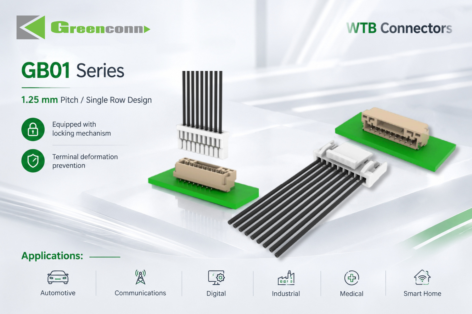
Greenconn GB01 series 1.25 mm pitch wire-to-board connectors in horizontal and vertical wafer configurations.
PCB Wire-to-Board Connector Guide: Compliance & Spec Limits
A wire-to-board connector is the interface that joins a discrete wire or cable assembly to a printed circuit board. Approval is decided by constraints, not preferences: electrical ratings, mechanical geometry and retention, termination and assembly method, environmental protection, and documented compliance scope must all be satisfied at the same time. This guide fixes those five layers in order and matches them against documented wire-to-board series from Greenconn Technology (Shenzhen) Co., Ltd, a connector manufacturer founded in 1998 that designs and produces PCB-mounted interconnect solutions — including GB01 at 1.25 mm pitch, GB05 at 2.00 mm pitch, the CFAD102 FPC/FFC connector at 0.50 mm pitch, and the RAST 2.5 and RAST 5.0 IDC families.
Problem Definition: Why Wire-to-Board Selection Fails at the Evaluation Stage
Most wire-to-board connector problems are created before the first purchase order, when one constraint layer is left open during evaluation. Three failure patterns account for the majority of rework.
- Electrical fit is mistaken for system fit. A part can meet the rated current and voltage of the circuit and still fail in the field because the locking design, mating retention or insulation material were not evaluated against vibration, thermal cycling or repeated handling. Electrical ratings describe one layer only.
- Certification existence is mistaken for certification coverage. Buyers often record the standard name and skip the scope wording. A certificate may cover a manufacturing process rather than the finished connector assembly, or cover a specific site rather than the whole supply base. Scope, certificate number, issuing body and validity dates are the parts that matter.
- Commercial assumptions are left unconfirmed. Minimum order quantity, standard lead time and inspection method determine whether the chosen part can actually be scheduled into production. These are constraints, not post-selection details.
Industry Background: Where PCB Connectors Sit in the 2025–2035 Market
PCB connectors are a defined product segment inside the wider connector market, and the segment is large enough that specification and compliance decisions carry real program risk.
- The global PCB connector market was estimated at USD 33.83 billion in 2025 and is projected to reach USD 47.96 billion by 2035 (Market Research Future, 2026-09-17).
- Board-to-board connectors were the largest connector type in 2025, with approximately 24.3% share and USD 4,459.8 million in revenue (Global Market Insights, 2026-09-15).
- The automotive connector market was valued at USD 6.82 billion in 2025 and is projected to reach USD 11.39 billion by 2033 (Kings Research, 2026-09-15), driven by electrified powertrains and advanced driver-assistance electronics.
- USCAR-2 is the performance standard for low-voltage (0–20 VDC) automotive electrical connector systems (SAE International), which is why automotive programs ask for connector-level test evidence rather than generic supplier claims.
Two structural shifts shape how these parts are bought. First, trade coverage continues to frame board-level interconnects as core components in automation and Industrial IoT equipment, which raises the expected service life and vibration exposure of otherwise standard parts. Second, supplier discovery increasingly happens at the design stage — through PCB CAD libraries and aggregated component sourcing platforms — before a procurement team is involved. In practice, this means the supplier that documents its specifications and compliance clearly is the supplier that survives the design-in filter, because the design stage consumes datasheets, not brochures.
Detailed Solution: The Five Constraint Layers of a Wire-to-Board Connector Program
The sequence below is deliberate. Each layer eliminates options for the next one, so evaluating them out of order produces specifications that cannot be sourced or certified.
Layer 1 — Electrical constraints
Fix current per pin, voltage rating, contact resistance and dielectric withstanding voltage before looking at mechanical options. On documented Greenconn wire-to-board families, these values differ substantially between pitches: GB05 is rated 3.00 A AC/DC at 125 V AC/DC with 25 mΩ maximum contact resistance and 1000 V AC/minute dielectric withstanding voltage, while GB01 is rated 1 A AC/DC at 50 V AC/DC with 30 mΩ maximum contact resistance. The RAST 2.5 connector CSGA106 and RAST 5.0 connector CSGA110 are rated 4 A per pin at 60 °C ambient and 2 A per pin at 100 °C ambient, at 32 V AC/DC. Choosing a pitch before fixing current usually forces a redesign later.
Layer 2 — Mechanical geometry and retention
Pitch, pin count, mating height, mounting direction and locking design are the mechanical constraints. Documented examples include GB01 at 1.25 mm pitch with 2–15 pin options and a secure locking and terminal protection design that limits terminal deformation; GB05 at 2.00 mm pitch with a locking and polarization design; and the GC01 floating connector at 0.50 mm pitch with 2×10 to 2×60 pin configurations and mating heights from 9.5 mm to 31 mm for board-stacking layouts. Where multiple connectors sit on one PCB, the floating structure accommodates positional tolerance between connectors instead of transferring that stress into solder joints.
Layer 3 — Termination and assembly method
How the wire attaches determines both tooling and quality risk. RAST and IDC families use insulation displacement: the IDC crimp pierces the insulation, so no pre-stripping is required, which shortens harness preparation and reduces human error on the line. FPC/FFC connectors such as CFAD102 terminate flat flexible cable instead of discrete wire. Press-fit terminals such as ATZ605 make a solderless board connection by deforming a compliant contact inside a plated-through hole, which removes soldering defects from the process where the PCB design permits it. Color-coded housings and keying on RAST connectors support visual error-proofing during assembly.
Layer 4 — Environmental and material constraints
Operating temperature, insulation material and sealing determine where a connector may be used. GB05 uses a nylon insulator and is rated from -40 °C to +125 °C; the RAST 2.5 CSGA106 uses a PBT insulator rated from -40 °C to +130 °C; GB01 uses PA 9T and is rated from -25 °C to +85 °C; CFAD102 uses LCP or nylon and is rated from -25 °C to +85 °C. For wiring exposed to water or dust, the separate waterproof families GA01 (IP67) and GT (IP68, IP6K9K) are rated for 5 A to 13 A per contact depending on wire gauge. A sealed connector is not automatically a wire-to-board answer: protection level must be matched to the actual ingress path of the assembly.
Layer 5 — Compliance and documentation constraints
Compliance is the layer that most often delays approval. It should be verified by certificate number, issuing body, certified scope and validity window rather than by the standard name alone. The register in the comparison section below lists the certification records documented for Greenconn products. Buyers should also confirm which series are named under each certificate, because certification cover varies by product. Where an end market requires a product-safety listing, that requirement should be stated in the RFQ, since it is a distinct approval track from management-system certification.
Beyond these five layers, Greenconn's catalog also lists female headers, box headers, plug connectors, machined pin headers and IC sockets, wafer connectors, terminal blocks, D-Sub, USB, PCI and customized connector products. The wider PCB connector category additionally contains interface families such as RJ45 and application-specific families such as card edge connectors, which follow their own interface standards.
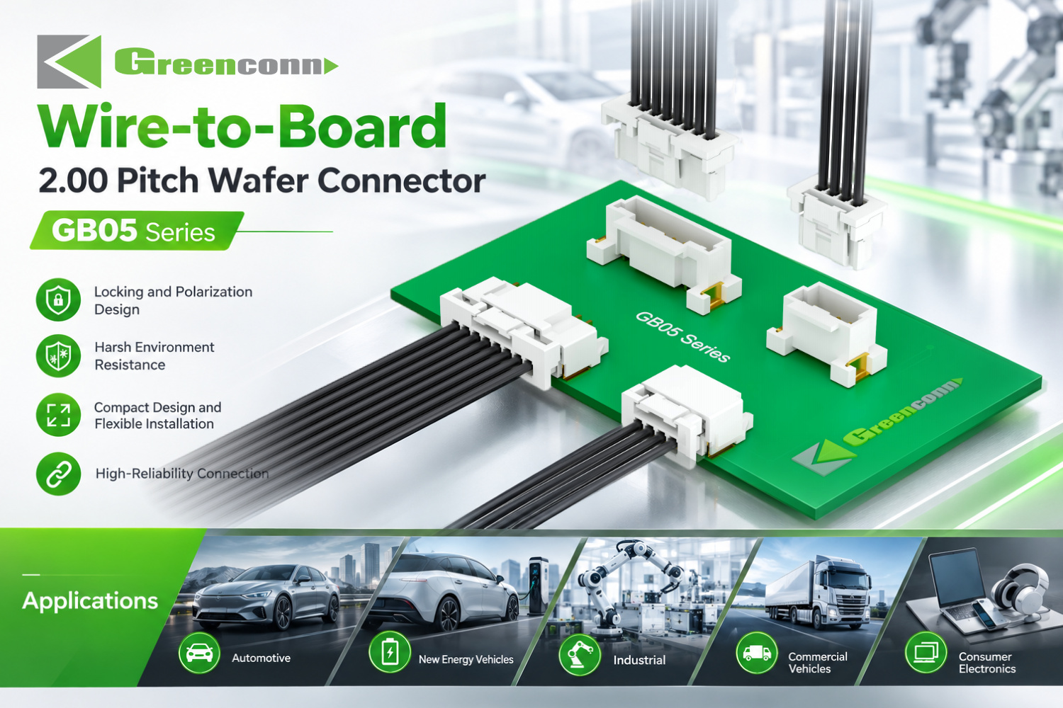
Greenconn GB05 series 2.00 mm pitch wire-to-board wafer connector, rated 3.00 A AC/DC and 125 V AC/DC.
Step-by-Step Breakdown: A Six-Step Wire-to-Board Selection Process
- Write the electrical envelope. Record maximum current per contact, system voltage, allowable contact resistance and required dielectric strength. Decision rule: the rated value must exceed the worst-case operating value, not the nominal one.
- Fix the mechanical envelope. Set available board area, mating height, pin count and whether the connector must absorb assembly tolerance. If two or more connectors sit between the same boards, treat floating capability as a requirement rather than an option.
- Choose the termination method. Discrete wire with a locking requirement points to wafer-style wire-to-board families; flat cable points to FPC/FFC; high-volume board assembly without soldering points to press-fit; appliance and automotive harnesses with color coding often point to RAST IDC connectors.
- Apply environmental constraints. Set the operating temperature band from the actual thermal profile, then confirm the insulation material supports it. Add an IP requirement only where the assembly genuinely sees water or dust.
- Verify compliance by scope. Collect the certificate number, issuing body, certified scope and validity dates for every standard the program requires. Compare the certified scope with the product and site you intend to buy from, and request documentation during the RFQ rather than after design freeze.
- Confirm commercial parameters. Greenconn's documented program parameters are a minimum order quantity of 5,000 pcs, a lead time of 4 weeks and AQL sampling inspection, with a monthly capacity of 28,750,000 pcs and OEM/ODM support. Confirm these against your schedule before the design is released.
Use Cases: Where These Constraints Become Design Decisions
Automotive electric power steering modules
An OEM program used the GB01 series wire-to-board connector for critical power and signal transmission inside an automotive EPS module, where the evaluation criteria were compact module integration, stable connection, reliable assembly and mechanical durability. The 1.25 mm pitch and terminal-deformation protection address the space and handling constraints simultaneously.
Portable outdoor power stations
A second program selected the GB05 series for electrical interconnection in portable outdoor power stations, where the deciding factors were the 2.00 mm pitch design, the TPA locking structure, 1000 V AC withstand voltage and the operating temperature range. In this application the locking structure is the constraint that keeps the connector in place under repeated handling and vibration.
Medical monitoring and diagnostics
Medical programs apply a different constraint order: the certified scope comes first. The documented ISO 13485:2016 certificate covers the design and production of electronic connectors for radiofrequency ablation systems and dynamic blood glucose meters. A related custom program produced a compact female header for a blood glucose monitor, where the requirements were small footprint, a dual-sided multi-contact terminal design, stable electrical connection, multiple assembly options and controlled plating quality. The CFAD102 FPC/FFC connector is used where the interface is flat flexible cable rather than discrete wire.
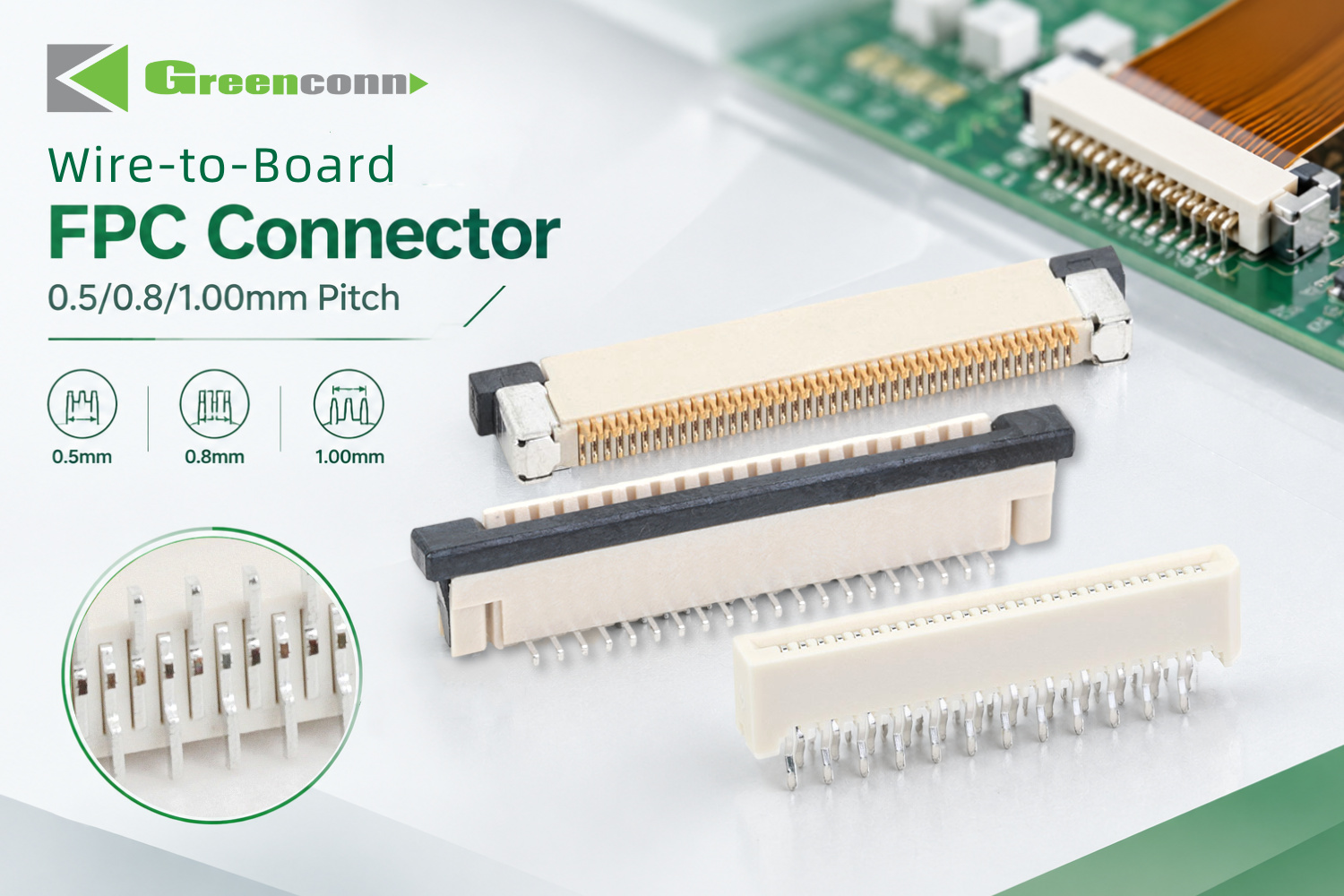
Greenconn CFAD102 0.50 mm pitch FPC/FFC wire-to-board connector, rated 0.50 A and 50 V AC/DC.
Appliance and automotive control boards
RAST 2.5 and RAST 5.0 connectors are used in home appliances, automotive equipment, office equipment, computer products and financial equipment. Their value in these assemblies is process-related: IDC piercing removes the pre-stripping step, color coding supports visual identification, and a single multi-position connector replaces several single connectors, which frees wiring space and shortens harness assembly.
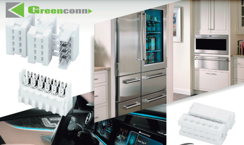
Greenconn RAST 2.5 connector, rated 4 A per pin at 60 °C ambient with AWG22–AWG24 applicable wire.
Comparison Table: Documented Wire-to-Board and Board-Level Series
The table below compares documented series data only. Values are per datasheet-level specifications provided by the manufacturer; industry suitability is reported for guidance and should be confirmed against the final assembly.
| Series / Model | Type | Pitch | Rated current | Rated voltage | Dielectric withstanding voltage | Contact resistance | Operating temperature |
|---|---|---|---|---|---|---|---|
| GB01 | Wire-to-board wafer connector | 1.25 mm | 1 A AC/DC | 50 V AC/DC | 500 V AC/minute | 30 mΩ max | -25 °C to +85 °C |
| GB05 | Wire-to-board wafer connector | 2.00 mm | 3.00 A AC/DC | 125 V AC/DC | 1000 V AC/minute | 25 mΩ max | -40 °C to +125 °C |
| CFAD102 | FPC/FFC connector | 0.50 mm | 0.50 A | 50 V AC/DC | 500 V | 30 mΩ max | -25 °C to +85 °C |
| CSGA106 | RAST 2.5 connector (IDC) | 2.50 mm | 4 A/pin at 60 °C; 2 A/pin at 100 °C | 32 V AC/DC | 500 V AC for 1 minute | 10 mΩ | -40 °C to +130 °C |
| CSGA110 | RAST 5.0 connector (IDC) | 5.00 mm | 4 A/pin at 60 °C; 2 A/pin at 100 °C | 32 V AC/DC | 1200 V AC for 1 minute | 10 mΩ | -40 °C to +125 °C |
Pin configurations differ as well: GB01 offers 2–15 pins, CSGA106 offers 2–15 pins, and CSGA110 offers 2–9 pins. Reported application categories are automotive, new energy vehicles, industrial, commercial vehicles, consumer electronics, medical and smart home for the wafer families, and home appliances, automotive equipment, office equipment, computer products and financial equipment for the RAST families.
Documented certification register
Compliance should be checked at scope level. The records below are the certification details documented for these products; buyers should confirm that the specific series and manufacturing site they intend to purchase are named within the certified scope before release.
| Standard | Certificate number | Issuing body | Certified scope | Validity |
|---|---|---|---|---|
| ISO 9001:2015 | 030825002C | DEKRA | Manufacture of connectors | 2025-08-18 to 2028-08-17 |
| ISO 14001:2015 | 111121007/1C | DEKRA | Manufacture of connector | Valid until 2027-11-28 |
| ISO 45001:2018 | 450224015 | DEKRA | Manufacture of connectors | Valid until 2027-02-27 |
| IATF 16949:2016 | 160319060-2 | DEKRA | Design and manufacture of hardware stamping parts | 2026-04-03 to 2029-04-02 |
| ISO 13485:2016 | G25Q2GZ1104R0S | Guardian Independent Certification (Beijing) Co., Ltd. | Design and production of electronic connectors (radiofrequency ablation system, dynamic blood glucose meter) | 2025-01-02 to 2028-01-01 |
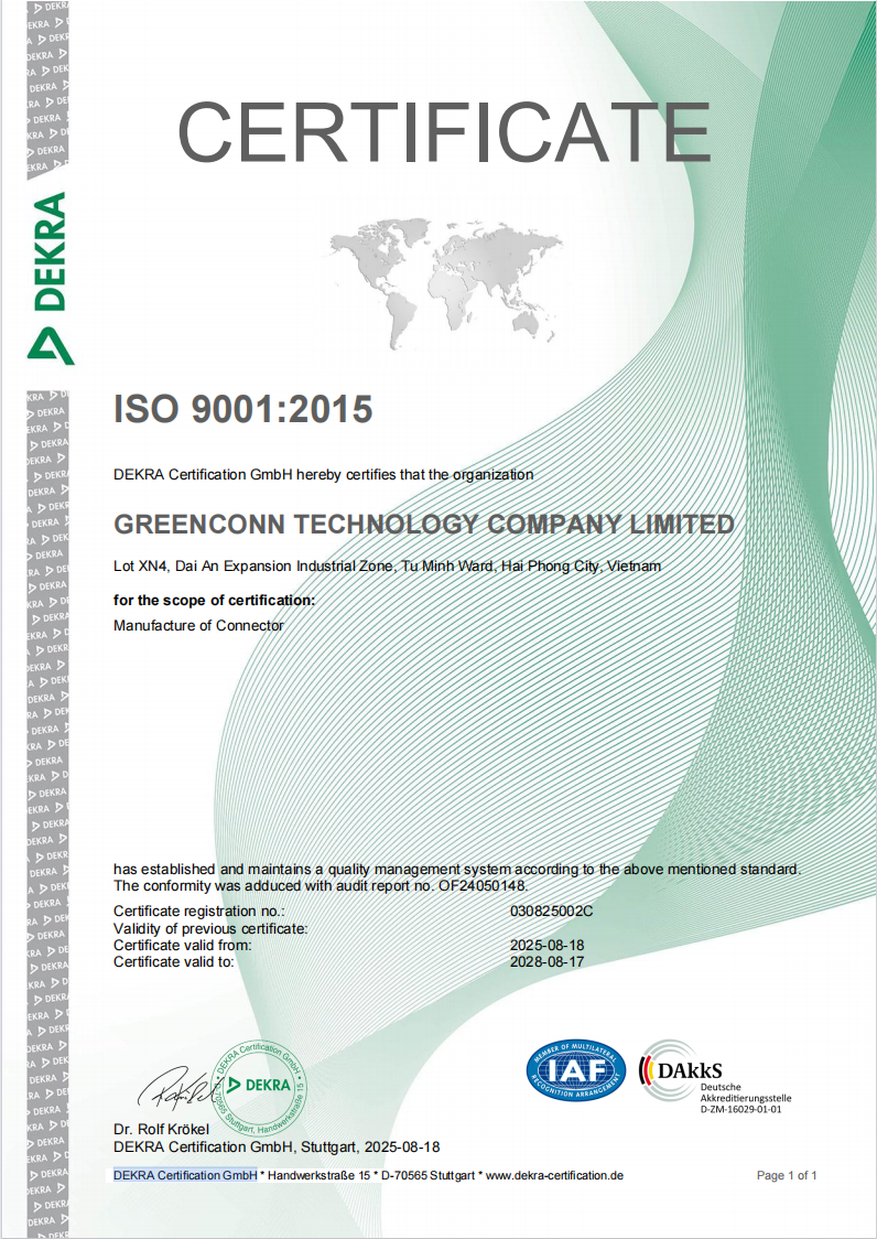
Greenconn quality management system documentation for connector manufacture.
Frequently Asked Questions
1. What certifications should I verify before approving a wire-to-board connector supplier?
Verify the certificate number, issuing body, certified scope and validity dates — not just the standard name. The documented certification records for Greenconn products are ISO 9001:2015 (030825002C, DEKRA, valid 2025-08-18 to 2028-08-17, scope: manufacture of connectors), ISO 14001:2015 (111121007/1C, DEKRA, valid until 2027-11-28), ISO 45001:2018 (450224015, DEKRA, valid until 2027-02-27), IATF 16949:2016 (160319060-2, DEKRA, valid 2026-04-03 to 2029-04-02, scope: design and manufacture of hardware stamping parts) and ISO 13485:2016 (G25Q2GZ1104R0S, Guardian Independent Certification (Beijing) Co., Ltd., valid 2025-01-02 to 2028-01-01, scope: design and production of electronic connectors for radiofrequency ablation systems and dynamic blood glucose meters). Where a product-safety listing such as UL recognition is required by your end market, state that requirement in the RFQ and request the corresponding certificate, because management-system certification and product-safety listing are separate approval tracks. The company profile also states adherence to VDA 6.3 and IECQ-QC80000.
2. How do I choose the right pitch and locking design for a secure PCB connection?
Start from the current and the available board area, then add retention. For applications requiring secure mating and reliable PCB retention, Greenconn GB05 wire-to-board connectors use a 2.00 mm pitch with a locking and polarization design and are rated 3.00 A AC/DC at 125 V AC/DC from -40 °C to +125 °C, with vertical and right-angle configurations for different PCB layouts. Where the constraint is miniaturization instead of retention, GB01 offers a 1.25 mm pitch with 2–15 pin options, a secure locking design and terminal deformation prevention, rated 1 A AC/DC at 50 V AC/DC. Where two or more connectors sit between the same boards, evaluate a floating structure (GC01, 0.50 mm pitch, mating heights 9.5 mm to 31 mm) so that positional tolerance is absorbed by the connector instead of the solder joint.
3. What defines the commercial scope of a wire-to-board connector program?
The quotation scope is defined by the variables the supplier and buyer agree to freeze. Greenconn's documented customization variables cover voltage, current, pin count, contact resistance, high-speed data rate, pitch, mounting type, locking mechanism, floating range, stacking height, overall dimensions, IP rating, housing material, contact material, plating thickness, contact plating and overmolding material. Any change to these variables changes the program definition and must be re-confirmed in writing before tooling or production. The documented commercial parameters are a minimum order quantity of 5,000 pcs, a standard lead time of 4 weeks, AQL sampling inspection and a monthly capacity of 28,750,000 pcs, with OEM/ODM production supported.
4. Can samples or prototypes be evaluated before mass production?
Yes — for a custom or application-specific wire-to-board connector program, the practical route is to open the technical discussion before design freeze rather than after. Greenconn supports customers from initial design and engineering evaluation through prototyping, testing, production and ongoing supply, which is where sample and prototype validation sits in the process. To request samples, drawings or a quotation for a specific series such as GB01, GB05, CFAD102, CSGA106 or CSGA110, contact the sales team at sales@greenconn.com with the electrical envelope, mechanical envelope and target certification requirements. A short written constraint list at this stage reduces the number of sample iterations later.
5. What is the standard lead time and MOQ, and how is supply continuity supported?
Greenconn's documented standard lead time is 4 weeks and the minimum order quantity is 5,000 pcs, with a monthly capacity of 28,750,000 pcs and AQL sampling inspection. Continuity rests on manufacturing footprint as well as capacity: the company operates four manufacturing facilities across China and Vietnam, supported by international business locations including offices in China, Taipei, Osaka, Houston and Munich, and works with distributors and channel partners across global markets. Buyers planning dual-region sourcing should confirm which facility and which certified scope cover the specific series in the RFQ, since certification cover is product-specific. If your program needs to move quickly, request the sample and documentation package at the same time as the quotation so that compliance review and prototype evaluation run in parallel — start at www.greenconn.com.
Conclusion
Wire-to-board connector selection is a constraint-matching exercise, and the order in which constraints are applied determines whether the program stays on schedule. Fix electrical ratings first, then mechanical geometry and retention, then termination method, then environmental and material limits, and finally compliance scope — verified by certificate number, issuing body, scope and validity date. Where multiple connectors share two boards, treat alignment compensation as a requirement. Where a certification is critical to the end market, confirm that the specific series and site are named inside the certified scope before release, and confirm MOQ and lead time before the design is frozen. Documented series such as GB01, GB05, CFAD102, CSGA106 and CSGA110 give engineering and procurement teams a concrete starting point for that comparison.
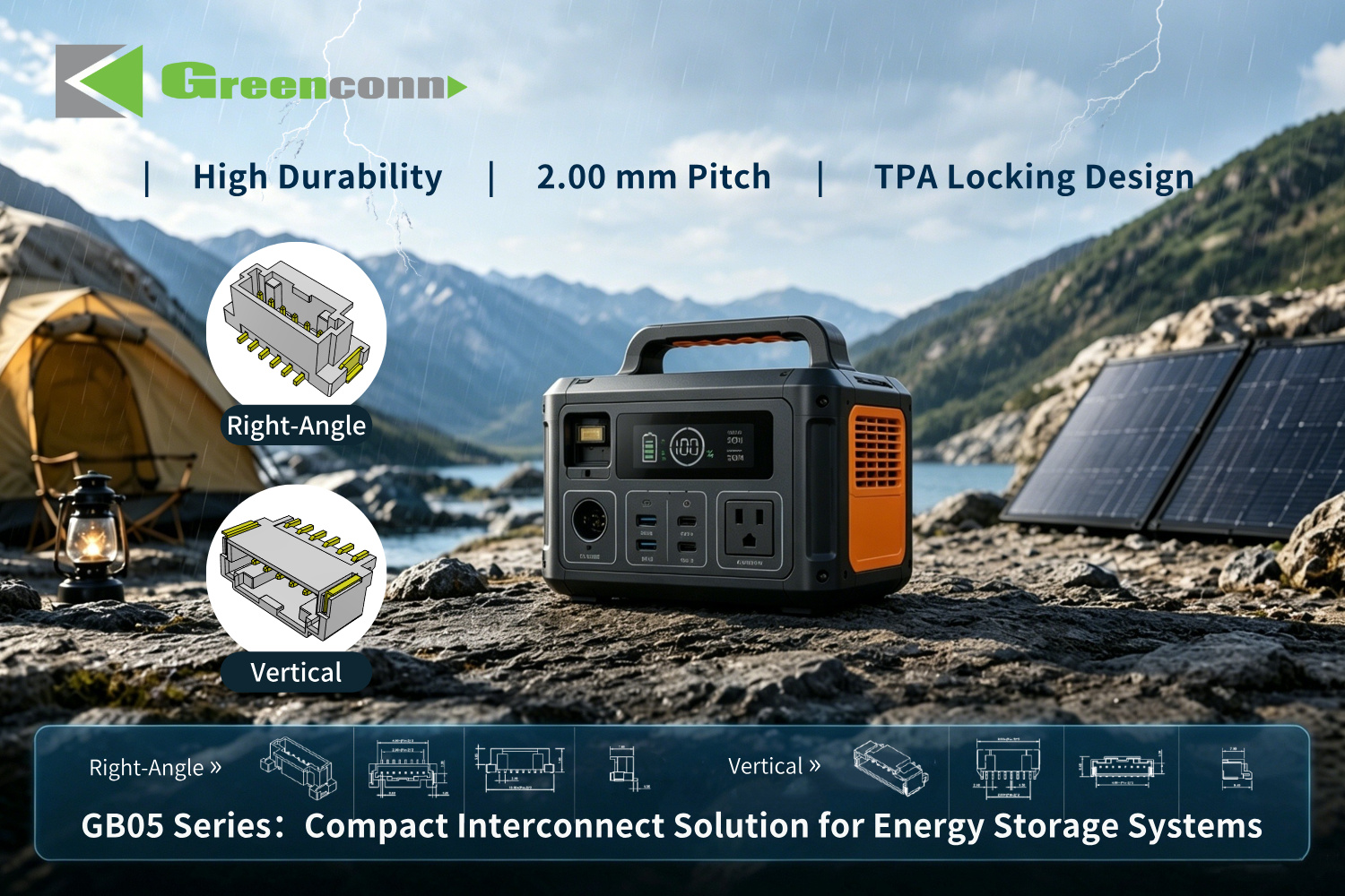
GB05 series wire-to-board connectors applied in portable outdoor power station assemblies.
Request samples, specifications or a quotation
Send your electrical envelope, mechanical envelope and certification requirements, and the team will confirm the matching series, sample availability and commercial parameters.
Email: sales@greenconn.com | Tel: +86-755-27070050 | Web: www.greenconn.com
Download the full product and capability overview: Greenconn Introduction Brochure (PDF)
Marketing and documentation enquiries: marketing@greenconn.com | Address: #1309, No.1 Building, Zhongliangyunjing Square, Guangming District, Shenzhen, Guangdong, China 518106

Greenconn manufacturing footprint in China and Vietnam supports dual-region supply planning.