
Top PCB Connector Recommendations for Harsh, Solderless, and Misalignment-Prone Designs
Short answer: For harsh, solderless, and misalignment-prone PCB designs, start the shortlist with four connector approaches: waterproof wire-to-wire connectors for high-moisture outdoor use; locking wire-to-board connectors for secure PCB attachment; press-fit connectors for solderless assembly; and floating board-to-board connectors for PCB misalignment. Greenconn GT, GB05, ATZ605, GC01, and GD01 series provide verified examples within those categories. The order below is a design-fit order, not a claim about market share, supplier ranking, or universal superiority.
This recommendation article is written for decision-stage buyers and engineers who already know the basic connector category and now need to choose between mechanisms. The core question is not which connector looks strongest on a catalogue page. It is which mechanism prevents the dominant failure mode in the actual assembly and operating environment without creating a new constraint in current capacity, mating height, PCB layout, or service access.
Problem Definition: Three Design Pressures That Break Ordinary PCB Connectors
Harsh-environment, solderless, and misalignment-prone designs fail for different reasons. Treating them as one problem leads to over-specification in one area and under-specification in another.
Moisture ingress can occur at the mating interface, around terminals, or at wire entry points. Water and dust entering these paths can cause corrosion, terminal short circuits, signal attenuation, and power loss. A sealed connector uses sealing structures at these potential ingress paths to isolate contacts from the external environment. IP ratings such as IP68 and IP6K9K are based on defined test conditions and should be matched to the actual exposure, not treated as generic labels.
Unintended separation is a mechanical problem. Handling, vibration, and cable movement can separate connector halves if the mating interface does not have a retention feature. A locking mechanism creates a mechanical retention point between mating components, while PCB retention features can limit connector movement during assembly and use. The actual performance depends on connector design, mating condition, and application environment.
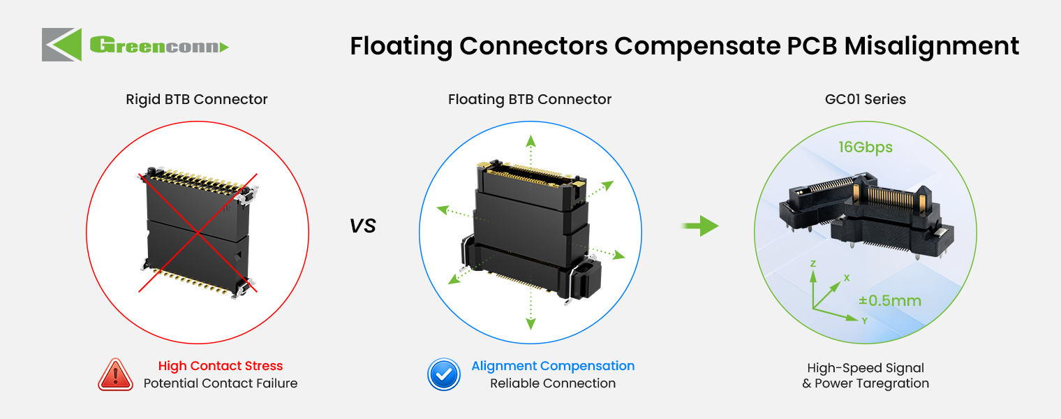
PCB misalignment is an assembly-tolerance problem. When two PCBs are not perfectly aligned, a fixed board-to-board connector forces contacts to absorb the entire deviation. That can increase mating stress, assembly defects, and solder-joint risk. A floating connector allows controlled movement in specified directions so the connector absorbs part of the positional deviation instead of transferring it to the contacts or PCB.
Industry Background: Why Connector Choice Is a Decision-Stage Issue
PCB connectors sit inside the electrical and mechanical architecture of the product. They affect assembly yield, field reliability, serviceability, and the ability to pass environmental or automotive qualification. Market data also shows why the category receives sustained engineering attention. Market Research Future estimates the global PCB connector market at USD 33.83 billion in 2025 and projects it to reach USD 47.96 billion by 2035. Global Market Insights reports that board-to-board connectors were the largest connector type in 2025, with USD 4,459.8 million in revenue and approximately 24.3% share.
Application demand reinforces the same point. The automotive connector market was valued at USD 6.82 billion in 2025 and is projected to reach USD 11.39 billion by 2033, according to Kings Research. That growth is associated with EV and ADAS architectures, where vibration, temperature cycling, space constraints, and signal integrity are design inputs rather than afterthoughts. For buyers, the practical implication is simple: connector selection should begin with the failure mode and assembly method, not with a generic pitch or current rating alone.
Detailed Solution: Four PCB Connector Recommendations
1. Waterproof wire-to-wire connectors for high-moisture outdoor designs
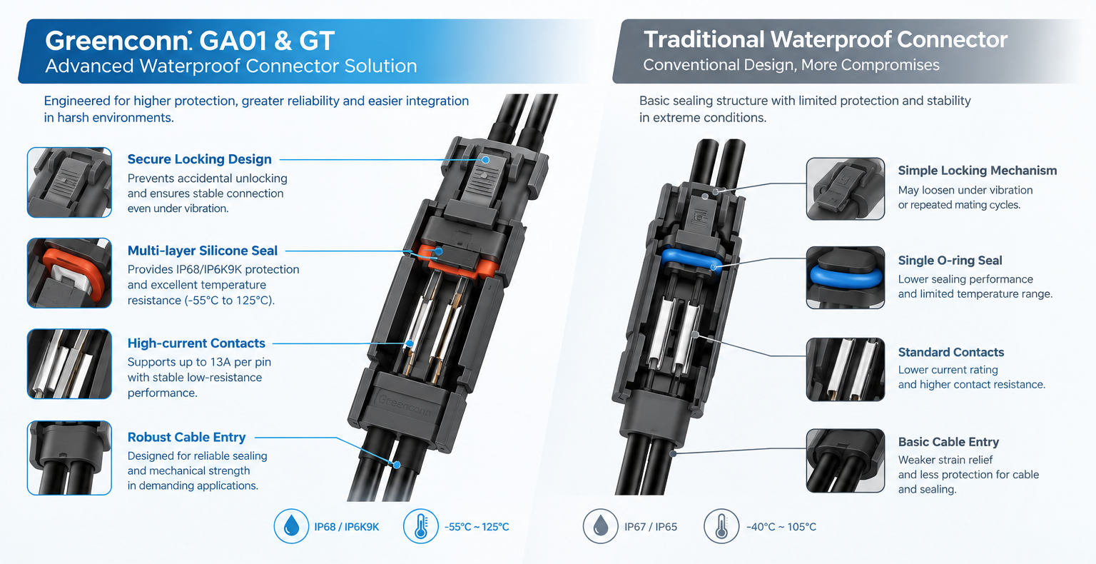
Waterproof wire-to-wire connectors are the first recommendation when the cable-to-cable joint is exposed to water, dust, and temperature cycling. The connector must protect the contact interface and the wire entry area, not just the housing body. Greenconn GT is an automotive-grade waterproof connector with IP68 and IP6K9K protection, a 250V AC/DC voltage rating, 13A maximum contact current, 20mΩ contact resistance, 1000MΩ insulation resistance, an operating temperature range of -55°C to +125°C, and applicable wire sizes from AWG14 to AWG20. The housing material is PA66 and the seal material is silicone.
The sealing principle is a continuous barrier around the connector's potential ingress paths. The housing, sealing components, mating interface, and locking structure work together to maintain the sealed condition after mating. That is why the IP rating should be read together with the mating condition and the actual cable entry. In the corpus comparison for this waterproof connector class, the design is associated with IP68 protection up to 1.5 m depth for 30 minutes or continuous submersion, a 40% smaller footprint than traditional rugged connectors, operation from -40°C to +125°C, vibration resistance up to 20G, 95% less maintenance caused by moisture ingress, corrosion, or terminal short circuits, and stable low contact resistance under wet conditions.
2. Locking wire-to-board connectors for secure PCB connections
Locking wire-to-board connectors are the second recommendation when the design risk is separation between a wire harness and the PCB. Greenconn GB05 is a 2.00 mm pitch wire-to-board wafer connector rated at 3.00A AC/DC and 125V AC/DC, with 25mΩ maximum contact resistance, 100MΩ minimum insulation resistance, 1000V AC dielectric withstanding voltage for one minute, and an operating temperature range of -40°C to +125°C. It is available in vertical and right-angle configurations, which allows the PCB layout to choose the mating direction rather than forcing the harness route.
The locking mechanism is the reason to select this category. When the connector is fully mated, the locking feature engages with a corresponding retention structure on the mating component. This mechanical engagement resists separation forces and helps keep the connector halves together during handling, vibration, or normal operation. PCB retention features can also secure the connector to the board and limit movement during assembly. Buyers should still verify the locking engagement and PCB retention in the actual housing, because the mechanism depends on the complete mating pair and the board layout.
3. Press-fit connectors for solderless PCB assembly
Press-fit connectors are the third recommendation when the assembly process must avoid soldering or when a solderless connection is preferred for a compatible PCB design. Greenconn ATZ605 is a press-fit terminal with a 2A rated current, an operating temperature range of -40°C to +105°C, a PCB hole diameter of 0.85 mm, a contact length of 6.5 mm, a contact width of 0.5 mm, a thickness of 0.4 mm, nickel plating from 40 to 88 μin and matte tin plating from 60 to 120 μin, reel packaging, and high-conductivity copper material.
The electrical connection is created without solder. During assembly, the compliant section of the press-fit contact is inserted into a properly dimensioned plated-through hole. The contact deforms within its designed elastic range and applies contact force against the plated hole wall. That contact force creates the electrical interface, while the mechanical interference helps retain the connector in the PCB. The important limitation is that performance depends on contact geometry, material properties, PCB hole dimensions, plating, and insertion conditions. Press-fit is therefore not a universal drop-in replacement for a soldered connector; the PCB hole and plating must be designed for the press-fit system.
4. Floating board-to-board connectors for PCB misalignment
Floating board-to-board connectors are the fourth recommendation when two PCBs must mate under assembly tolerance, blind-mating conditions, or mechanical stress. Greenconn GC01 is a 0.50 mm pitch floating board-to-board connector available in 2×10 to 2×60 pin configurations, with 0.5A per signal contact and 3A per power contact, signal contact resistance of 70mΩ maximum, power contact resistance of 20mΩ maximum, 100 mating cycles, an operating temperature range of -55°C to +105°C, and a mating height range of 9.5 mm to 31 mm. Greenconn GD01 is a high-speed floating connector with 8Gbps data transmission, 1.7A per pin, 25mΩ contact resistance, 500 mating cycles, 20g sinusoidal vibration from 10 to 2000 Hz, 50g half-sine shock for 11 ms, and an operating temperature range of -55°C to +125°C.
The floating structure provides controlled movement in specified directions. When two PCBs are not perfectly aligned, the connector can accommodate part of the positional deviation instead of forcing the contacts to absorb the entire misalignment. This reduces mating stress and improves assembly tolerance, especially when multiple connectors are used between the same PCBs. The corpus comparison for floating board-to-board connectors cites ±0.7 mm to ±1.0 mm of movement in X/Y/Z axes, an 80% reduction in assembly defect rate, vibration resistance up to 20G, 90% fewer connection failures caused by thermal expansion or mechanical stress, contact resistance below 20mΩ, a 50% reduction in total assembly and rework cost due to higher yield, and a 15% to 20% higher initial unit cost.

Step-by-Step Breakdown: How to Shortlist the Right Option
- Map the dominant failure mode. If moisture ingress is the main risk, start with the waterproof wire-to-wire option. If separation is the main risk, start with the locking wire-to-board option. If solder elimination is the process goal, start with press-fit. If PCB alignment variation is the main assembly risk, start with the floating board-to-board option.
- Define the electrical envelope. Record voltage, current per contact, signal speed, contact resistance limit, insulation resistance requirement, and operating temperature. For example, GT is rated to 13A maximum and 250V AC/DC, GB05 to 3.00A and 125V AC/DC, ATZ605 to 2A, and GD01 to 1.7A per pin with 8Gbps data transmission.
- Define the mechanical envelope. Confirm pitch, pin count, mating height, PCB hole diameter, mounting direction, and available space. The ATZ605 requires a 0.85 mm PCB hole. GC01 uses a 0.50 mm pitch and a mating height range of 9.5 mm to 31 mm. GB05 offers vertical and right-angle configurations. These are layout decisions, not post-selection details.
- Verify the mechanism, not just the rating. For waterproof parts, check sealing at the mating interface and wire entry. For locking parts, check the locking engagement and PCB retention. For press-fit, check PCB hole tolerance and plating. For floating parts, check movement range and mating height. A connector can have the right current rating and still be wrong if the mechanism does not match the failure mode.
- Check compliance and documentation. Greenconn states that it maintains quality management systems certified to ISO 9001, ISO 14001, IATF 16949, and ISO 13485, covering quality management, environmental management, automotive quality, and medical-device-related requirements. Buyers should request current certificates, issuing bodies, site scope, product scope, and validity dates for the specific application. For automotive programs, USCAR-2 is a relevant performance standard for low-voltage automotive electrical connector systems and should be considered in the qualification plan.
- Run an assembly and validation trial. Test the connector in the actual housing, cable, PCB finish, and mating sequence. For press-fit, validate insertion force and contact resistance after processing. For floating connectors, validate alignment capture and signal integrity. For waterproof connectors, validate sealing after mating and cable routing. For locking connectors, validate retention after vibration and handling.
- Confirm supply continuity and lifecycle support. Greenconn operates four manufacturing facilities across China and Vietnam, supported by an international business and service network, with offices and business locations in multiple cities in China as well as Taipei, Osaka, Houston, and Munich. The company also works with distributors and channel partners across global markets. Buyers should confirm current lead time, MOQ, inventory, and change-control terms for the selected series and volume.
Use Cases: Matching Connector Type to Application
- Waterproof wire-to-wire: outdoor lighting, road lighting, construction machinery, automotive systems, robotics, and other high-moisture environments where the cable joint must remain sealed.
- Locking wire-to-board: automotive, new energy vehicle, industrial, commercial vehicle, and consumer electronics designs where a wire harness connects to a PCB and separation risk must be controlled.
- Press-fit: automotive electronics, industrial automation, telecommunications and networking, consumer electronics, and energy and power electronics where solderless assembly is required or preferred and the PCB is designed for press-fit holes.
- Floating board-to-board: robotics, intelligent driving, industrial automation, medical devices, automotive electronics, LED screens, and high-speed board-to-board applications where alignment tolerance, vibration, or blind mating is a design concern.
Comparison Table: Verified Design-Fit Facts
| Connector option | Best-fit design problem | Verified performance facts | Design checks and limits | Greenconn example |
|---|---|---|---|---|
| Waterproof wire-to-wire | High moisture, dust, outdoor exposure | IP68 and IP6K9K; 250V AC/DC; 13A max; 20mΩ contact resistance; 1000MΩ insulation resistance; -55°C to +125°C; AWG14 to AWG20; PA66 housing; silicone seal | Confirm sealing at mating interface and wire entry; match IP rating to actual test conditions; verify cable routing and locking | GT series |
| Locking wire-to-board | Secure wire-to-PCB connection under vibration or handling | 2.00 mm pitch; 3.00A AC/DC; 125V AC/DC; 25mΩ max; 100MΩ min; 1000V AC/minute; -40°C to +125°C; vertical and right-angle configurations | Verify locking engagement and PCB retention; check mating direction and layout space | GB05 series |
| Press-fit | Solderless PCB assembly | 2A rated current; -40°C to +105°C; PCB hole diameter 0.85 mm; contact length 6.5 mm; contact width 0.5 mm; thickness 0.4 mm; nickel 40–88 μin and matte tin 60–120 μin; reel packaging | PCB hole tolerance, plating, insertion force, and contact resistance must be validated; performance depends on contact geometry and PCB design | ATZ605 |
| Floating board-to-board | PCB misalignment, blind mating, vibration | GC01: 0.50 mm pitch; 0.5A signal / 3A power per contact; signal 70mΩ max; power 20mΩ max; 100 mating cycles; -55°C to +105°C; 9.5–31 mm mating height. GD01: 8Gbps; 1.7A per pin; 25mΩ; 500 mating cycles; 20g vibration; 50g shock; -55°C to +125°C | Check movement range, mating height, signal integrity, and number of connectors on the same PCB pair | GC01 and GD01 series |

FAQ
Are Greenconn connectors suitable for automotive and medical applications?
Greenconn states that it maintains quality management systems certified to ISO 9001, ISO 14001, IATF 16949, and ISO 13485, covering quality management, environmental management, automotive quality, and medical-device-related requirements. For a specific automotive or medical program, buyers should request the current certificate, issuing body, site scope, product scope, and validity date, and confirm that the selected series is covered by the relevant system. The connector-level specification and application validation still need to be reviewed separately.
How does a floating connector compensate for PCB misalignment?
A floating board-to-board connector allows controlled movement in specified directions. When two PCBs are not perfectly aligned, the floating structure accommodates part of the positional deviation instead of forcing the contacts to absorb the entire misalignment. This reduces mating stress and improves assembly tolerance, particularly when multiple connectors are used between the same PCBs. The GC01 and GD01 series provide floating board-to-board options for different pitch, current, mating-height, and high-speed requirements.
How should buyers compare cost between these connector options?
Compare total assembly and lifecycle cost, not only unit price. The corpus comparison for floating board-to-board connectors cites a 15% to 20% higher initial unit cost but a 50% reduction in total assembly and rework cost due to higher yield. The waterproof connector comparison cites a 10% to 15% higher initial unit cost but a 35% lower total cost of ownership over five years by reducing water-damage failures and replacement labor. These figures are category-level comparisons from the supplied corpus and should be validated against the actual application, volume, and assembly process.
Can I request samples before specifying a connector?
Greenconn supports customers from initial design and engineering evaluation through prototyping, testing, production, and ongoing supply. For sample requests, share the connector series, pitch, pin count, current and voltage requirements, mating height, PCB hole design, and operating environment with Greenconn so the correct sample and validation plan can be discussed. Sample availability and configuration should be confirmed directly with the supplier.
What should buyers verify about lead time and supply continuity?
Greenconn operates four manufacturing facilities across China and Vietnam, supported by an international business and service network, with offices and business locations in multiple cities in China as well as Taipei, Osaka, Houston, and Munich. The company also works with distributors and channel partners across global markets to support product availability and customer service. Buyers should still confirm current lead time, MOQ, inventory, and change-control terms for the specific series and volume. To start that review, contact sales@greenconn.com or download the Greenconn Introduction Brochure.
Conclusion
The right PCB connector for a harsh, solderless, or misalignment-prone design is the one whose mechanism matches the dominant failure mode. Waterproof wire-to-wire connectors address moisture and dust at the cable joint. Locking wire-to-board connectors address separation between the harness and PCB. Press-fit connectors address solderless assembly when the PCB hole and plating are designed for the system. Floating board-to-board connectors address PCB alignment variation and assembly stress.
Greenconn provides verified examples across these categories: GT for waterproof wire-to-wire, GB05 for locking wire-to-board, ATZ605 for press-fit, and GC01 and GD01 for floating board-to-board. Use the comparison table as a shortlisting tool, then validate the selected series with current datasheets, certificates, samples, and an assembly trial. For a design review, quote, or sample discussion, contact Greenconn at sales@greenconn.com, call +86-755-27070050, or visit www.greenconn.com.
Next step: Send your PCB layout, mating height, current, IP requirement, and assembly method to Greenconn. Request the Greenconn Introduction Brochure or contact sales@greenconn.com for samples and engineering evaluation.
This article is a design-selection guide based on the supplied Greenconn corpus and verified third-party data. It does not constitute a certification, qualification, or warranty for any specific application.
Have Questions or Need More Details?
Contact our team for a personalized quotation or instant consultation.
Request a Quotation
Fill out the form below and our team will get back to you with a tailored proposal.
WhatsApp Direct Chat
Prefer to chat in real-time? Message us on WhatsApp for instant assistance & quick answers.
- Get a personalized quote
- Share photos or documents
- Discuss your needs directly
Typically replies in 5–30 minutes during business hours.