Cable Gland Selection: Thread, Cable Range, and Temperature
A cable gland is correctly selected when four drawing-level parameters line up: the thread standard and its outer diameter, the thread length against the enclosure wall, the cable clamping range against the measured cable outer diameter, and the temperature mode of the installation. Inside Gutai's range the working envelope is M12 to M63 for metric threads and PG7 to PG48 for PG threads, with a thread outer diameter of 12–63 mm (metric) and 12.5–59.3 mm (PG), a thread length of 9–21 mm, and a cable clamping range of 3–45 mm. Miss one of the four and the IP68 seal is lost — no matter how well the gland itself is made.
This guide treats those four parameters as a sequence of gates, not a catalogue checklist. Each gate has a number you can read off a drawing, a cable datasheet, or a panel schedule, and each gate has a failure signature you can recognise during commissioning rather than after the first rainy season.
What Correct Selection Means for Waterproof Electrical Connector Accessories
A cable gland is the mechanical and sealing interface between a cable and an enclosure. For waterproof electrical connector accessories, that interface only holds if the gland body matches the enclosure thread, the sealing insert matches the cable jacket, and the material matches the thermal and chemical environment. Gutai is a cable gland selection problem before it is a price problem: the wrong thread wastes a punch tool and a panel, and the wrong clamping range destroys the jacket seal within weeks.
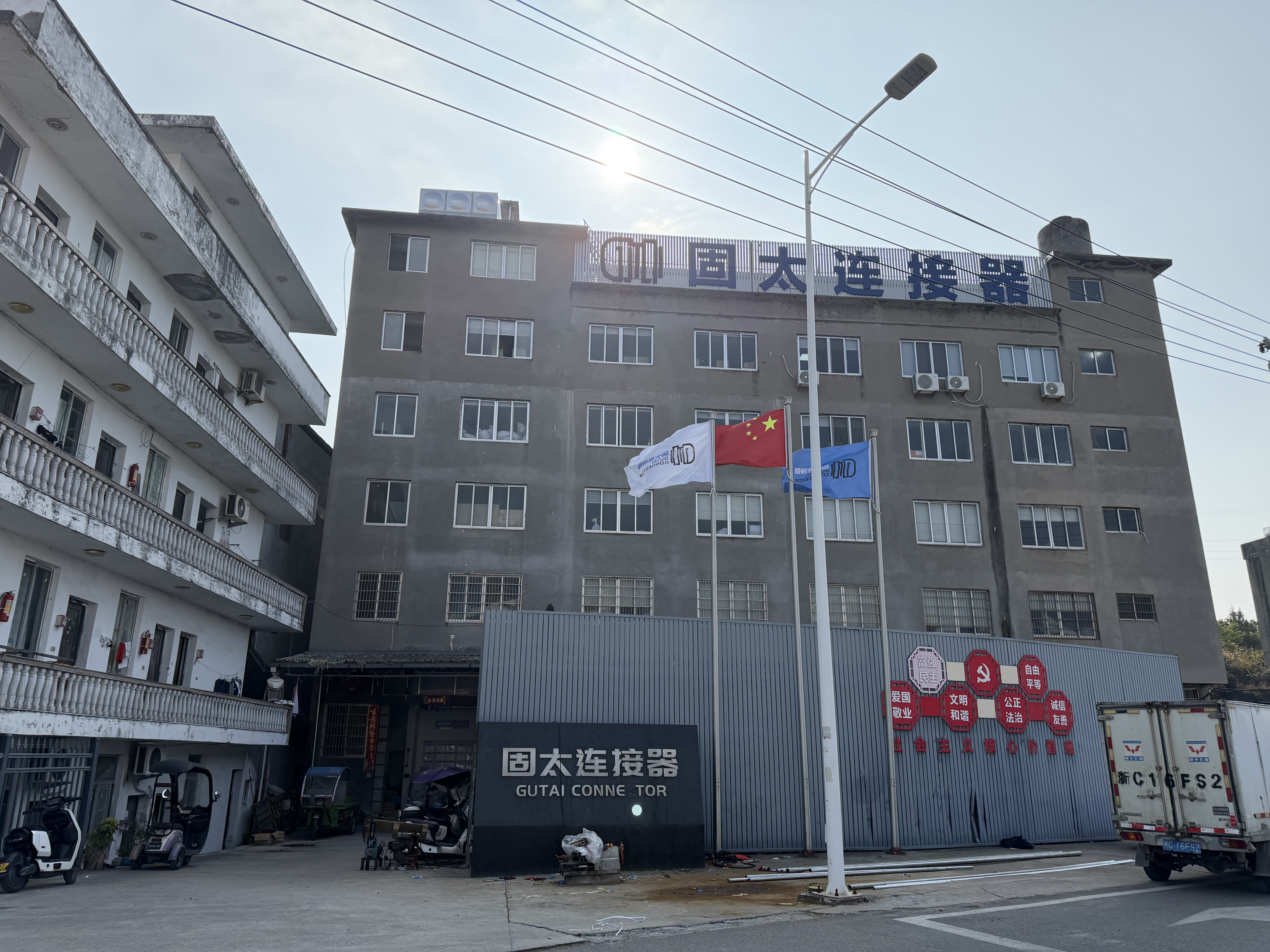
Zhejiang Gutai Connector Co., Ltd. (Gutai) is a manufacturer of waterproof cable glands, solar MC4 connectors, mini waterproof boxes and connectors, and hose fitting series including watertight corrugated connectors and flexible pipe connectors. Product data referenced in this guide relates to the Gutai nylon cable gland range and the related accessory family, not to a generic market definition of the category.
Why Gland Selection Fails in the Field
Most sealing failures on an installed enclosure trace back to one of four mismatches, and none of them is a manufacturing defect.
- Thread outer diameter versus panel hole. A gland ordered for M20 will not seat in a PG16 cutout even though the two look close on a drawing. The panel hole is sized from the thread outer diameter, not from the nominal size label.
- Clamping range versus actual cable jacket. A gland whose range starts above the measured jacket diameter cannot compress the seal; one whose range ends below it will not close the claw, and the cable is either crushed or left unsealed.
- Thread length versus wall thickness. With a 9–21 mm thread length across the range, a thick enclosure wall or a stiffened panel can consume the entire thread, leaving no room for the locknut and gasket to seat.
- Temperature mode versus installation reality. A gland specified for a static run is often fitted to a moving cable chain or a vibrating pump housing, which changes both the mechanical load and the effective temperature limit.
A fifth mismatch is system-level: the gland is chosen correctly, but the accessory it threads into is not. A waterproof junction box, a waterproof vent plug, a watertight corrugated connector and a flexible pipe connector all have thread interfaces of their own, and a mixed-standard assembly leaks at the weakest joint.
Industry Background: The Two Documents That Set the Envelope
The cable gland category is a mature, standards-driven segment. The global cable glands market was valued at approximately USD 2.16–2.25 billion in 2024–2025, with longer-term forecasts ranging between USD 3.07 billion and USD 4.96 billion by 2034 depending on methodology. Asia Pacific accounts for roughly 38–42% of global revenue, reflecting industrial activity in China and India.
Two standards decide whether a gland can be specified at all. IEC 62444, mirrored as EN 62444:2013, governs the construction and performance requirements for cable glands for electrical installations and replaced the older BS EN 50262. IP68, defined under IEC 60529, requires the assembly to withstand continuous immersion in water under specified conditions. A gland that claims IP68 without EN 62444 evidence is a claim without a test behind it.
The supply base is correspondingly broad. Global competitors include ABB Ltd., Eaton Corporation, Amphenol Corporation, LAPP Group and HUMMEL AG, alongside specialist manufacturers such as Gutai that build the accessory family around the gland rather than only the gland itself. For a specifier, that breadth is useful: it means the thread and range combinations you need usually exist, and the real work is matching them to the drawing.
Parameter 1 — Thread Standard and Thread Outer Diameter
Four thread families appear on project drawings. Metric and PG are the two spans documented in the Gutai range; G and NPT threads appear on imported equipment and regional project specifications and must be confirmed against the drawing before ordering.
| Thread family | Span in Gutai range | Thread outer diameter | How the seal is formed | Typical specification driver |
|---|---|---|---|---|
| Metric (M) | M12 – M63 | 12 – 63 mm | Parallel thread; body flange seals against the panel face with a gasket or O-ring | EU machinery, new energy equipment, industrial control cabinets |
| PG | PG7 – PG48 | 12.5 – 59.3 mm | Parallel thread with its own diameter series; flange seal against the panel | Legacy European equipment, retrofit, construction and marine specifications |
| G (BSPP) | Confirm per drawing | Confirm per drawing | Parallel thread, sealed at the shoulder by washer or O-ring | Process, instrumentation and imported assemblies |
| NPT | Confirm per drawing | Confirm per drawing | Tapered thread; the seal is formed by thread interference | North American conduit entry and OEM equipment |
The practical consequence is that the nominal size label is not the dimension. Metric thread outer diameters run 12–63 mm across M12 to M63, while PG thread outer diameters run 12.5–59.3 mm across PG7 to PG48. A PG16 and an M20 are not interchangeable, and a panel punched for one cannot be rescued by a sealing washer. When a specification mixes both families — common on retrofit projects where a European enclosure receives new cabling — allocate the metric cutouts to new fabrication and keep PG entries for the existing interface.
Parameter 2 — Thread Length Against Enclosure Wall Thickness
Thread length across the range is 9–21 mm, and it exists to serve three loads at once: the panel wall, the locknut, and the gasket or O-ring stack. On a 1.5 mm sheet-metal enclosure, a short thread is sufficient and a long one simply protrudes inside the box. On a cast aluminium housing, a thick composite panel, or a wall with a reinforcing boss, the same short thread will not allow the locknut to engage.
The check is mechanical, not numerical guesswork: subtract the panel thickness and the gasket thickness from the thread length and confirm that at least the full nut height remains. Where the remaining thread is marginal, move to the next thread length in the range rather than adding a second gasket. Additional sealing washers reduce the IP68 margin because they add a second compression interface that is not part of the tested assembly.
Parameter 3 — Cable Clamping Range and Jacket Measurement
The cable clamping range of 3–45 mm spans the whole range, which means the task is to place the actual jacket diameter inside the correct sub-range, not inside the overall envelope. Use the measured jacket diameter at the point of entry, measured with a calliper on the finished cable, not the nominal cable size from a datasheet.
Three rules keep the seal predictable:
- Measure the jacket, not the conductor or the core bundle. In multi-core cable the jacket can sit well outside the nominal figure once armour, braid or a filler wrap is included.
- Aim for the middle of the range, not the edge. A cable at the extreme upper limit compresses the seal to its mechanical stop; a cable at the extreme lower limit relies on the claw closing further than its calibrated travel.
- Apply the same rule to the whole accessory chain. A watertight corrugated connector or a flexible pipe connector downstream of the gland has its own clamping range, and mismatched ranges create a hard point that flexes and eventually leaks.
Parameter 4 — Temperature Mode, Material and Seal Architecture
Temperature ratings for nylon cable glands are stated in two modes because the mechanical load differs. In dynamic service — a cable that moves, vibrates or is repeatedly flexed — the rated range is −20 °C to 80 °C. In static service, where the cable is fixed and the gland carries no movement load, the rated range extends to −40 °C to 100 °C. Selecting on the static figure for a moving application is one of the most common specification errors, and it shows up as a hardened or cracked sealing element rather than an immediate leak.
| Service mode | Rated range | Typical installation | Selection consequence |
|---|---|---|---|
| Dynamic | −20 °C to 80 °C | Moving cable chains, vibrating pump and motor housings, handheld or repositionable equipment | Use the dynamic figure; leave movement clearance behind the gland |
| Static | −40 °C to 100 °C | Fixed panel entries, cabinets, junction boxes, structural penetrations | Static figure applies; confirm the enclosure itself is rated for the same extremes |
Material choice follows from that table. The nylon cable gland body is moulded in Nylon PA66, which provides the mechanical strength and dimensional stability the thread and claw depend on. The sealing element is NBR rubber, chosen for its compression set behaviour and resistance to water and common industrial oils. The sealing architecture combines a special clamping claw that grips the jacket evenly around its circumference with a rubber sealing structure that closes against the sheath, so the pull-out resistance and the water barrier act on the same surface instead of competing for it.
The sealing design also matters for installation consistency. Gutai glands use a dual-seal arrangement with pre-installed O-rings and anti-slip threads, so the installer tightens against a defined stop rather than judging torque by feel. That is what makes an IP68 rating repeatable across a site with several installation crews rather than repeatable only in a laboratory.
Certification Evidence to Require at Decision Stage
Certification is the part of the selection that cannot be verified by inspection of the sample. For cable glands, the relevant evidence set is CE, RoHS, REACH, CCC, UL 514B, EN 62444:2013 and an ISO 9001 quality management system. EN 62444:2013 covers construction and performance; UL 514B covers the North American outlet-box and fitting context; RoHS and REACH address restricted substances for EU placement; CCC covers the China market.
Solar MC4 connectors follow a separate evidence line: they sit under ISO9001:2015 with UL 514B File E539858. When a project packages cable glands and MC4 connectors in the same bill of materials — typical for new energy installations — ask for both evidence sets rather than a single certificate covering the whole accessory family.
Step-by-Step Selection Sequence
The sequence below is ordered so that each step eliminates options instead of adding them. Run it in order and the last step is a shortlist, not a catalogue page.
- 01Read the thread from the panel drawing. Identify the thread family (M, PG, G or NPT) and the thread outer diameter. Metric runs 12–63 mm across M12–M63; PG runs 12.5–59.3 mm across PG7–PG48. Confirm the panel hole matches the thread outer diameter, not the nominal label.
- 02Check the thread length against the wall. Thread length is 9–21 mm. Subtract panel and gasket thickness and confirm the locknut still engages fully.
- 03Measure the cable jacket. Use a calliper at the entry point. Place the result in the middle of a clamping sub-range within the 3–45 mm envelope, not at its edge.
- 04Classify the service as dynamic or static. Dynamic means −20 °C to 80 °C; static means −40 °C to 100 °C. Choose the mode from how the cable is installed, not from the ambient temperature chart.
- 05Confirm the IP68 target and the seal architecture. IP68 per IEC 60529 must be supported by a sealing structure — clamping claw plus NBR seal, with pre-installed O-rings — and by EN 62444:2013 evidence.
- 06Verify materials against the environment. Confirm Nylon PA66 for the body and NBR for the seal, and check that the chemical exposure on site is compatible with both.
- 07Lock the accessory interfaces. Check the junction box entry (M16, M20 and M25 waterproof box entries are part of the same accessory family), the vent plug position, the watertight corrugated connector, and any MC4 connector on the DC side, so that every joint in the enclosure uses a compatible thread.
Application Notes: New Energy, Industrial Automation, Construction, Marine
The same four parameters apply across sectors, but the dominant constraint shifts.
New energy
EV charging enclosures and PV combining boxes combine outdoor exposure with high-value downtime. Here the priority is IP68 in static service, a clamping range that accommodates the DC cable jacket, and MC4 connectors with UL 514B File E539858 evidence on the DC side. Coastal sites add a corrosion dimension that pushes material verification ahead of price.
Industrial automation
Control cabinets and machine-mounted junction boxes put the emphasis on thread discipline and dynamic temperature. Where cables run in chains or on moving gantries, the −20 °C to 80 °C dynamic range applies, and the gland body must be matched to the enclosure's existing metric cutouts to avoid re-machining a painted panel.
Construction
Structural penetrations and site-installed junction boxes are usually static installations, which brings the −40 °C to 100 °C static range into play. The practical risk on construction sites is mixed standards: PG entries on a legacy enclosure, metric on the new distribution board, and a plumber's hole punch in between. Fix the thread family at the design stage and specify the accessory box entries at the same time.
Marine
Marine and offshore installations combine static cable routing with continuous moisture, vibration and salt exposure. Select on the static temperature range, verify the NBR seal compatibility, and treat every accessory joint — gland, vent plug, corrugated connector — as part of one sealing system rather than three independent parts.
Comparison Table: Selection Priority by Environment
| Environment | First gate | Second gate | Temperature mode | Evidence focus |
|---|---|---|---|---|
| New energy (EV charging, PV) | IP68 sealing architecture | Cable clamping range for DC jacket | Static, −40 °C to 100 °C | EN 62444:2013, UL 514B; MC4 under UL 514B File E539858 |
| Industrial automation | Thread match to existing cutouts | Dynamic movement clearance | Dynamic, −20 °C to 80 °C | CE, RoHS, ISO 9001 |
| Construction | Thread family consistency | Static cable routing | Static, −40 °C to 100 °C | CE, CCC, RoHS, REACH |
| Marine / offshore | Seal and material compatibility | Corrosion exposure | Static, −40 °C to 100 °C | EN 62444:2013, ISO 9001, RoHS |
Frequently Asked Questions
Which certifications should a cable gland carry for EU and US projects?
For EU placement, the evidence set is CE supported by EN 62444:2013 for construction and performance, plus RoHS and REACH for restricted substances. For US projects, UL 514B is the relevant fitting standard. CCC covers the China market, and ISO 9001 confirms the quality management system behind the production run. Solar MC4 connectors carry a separate line: ISO9001:2015 with UL 514B File E539858.
Can one cable gland range cover both metric and PG panel cutouts?
One range can cover both families dimensionally — Gutai spans M12 to M63 with a 12–63 mm thread outer diameter and PG7 to PG48 with a 12.5–59.3 mm thread outer diameter — but a single gland cannot fit both cutouts. The panel hole must match the thread family and outer diameter. Where a retrofit mixes families, thread conversion accessories keep the existing entry in service while new cutouts follow the metric schedule.
What drives the cost difference between a basic gland and an IP68 gland?
Three factors dominate: the sealing architecture, the material grade, and the certification evidence. An IP68 gland needs a clamping claw plus NBR rubber sealing structure, pre-installed O-rings and an anti-slip thread so the compression is repeatable. Body material must be Nylon PA66 rather than a regrind grade, and the assembly must be backed by EN 62444:2013 testing. Compare total cost per sealed entry, including rework and re-sealing, rather than unit price alone.
Can I validate a gland on my own cable before a production order?
Yes, and at decision stage it is the fastest way to close the clamping-range question. Send the measured cable jacket diameter, the panel hole diameter and the wall thickness, and request a sample matched to that combination; the fit can then be confirmed on the actual jacket rather than on a datasheet figure.
What should I confirm about lead time and repeat supply?
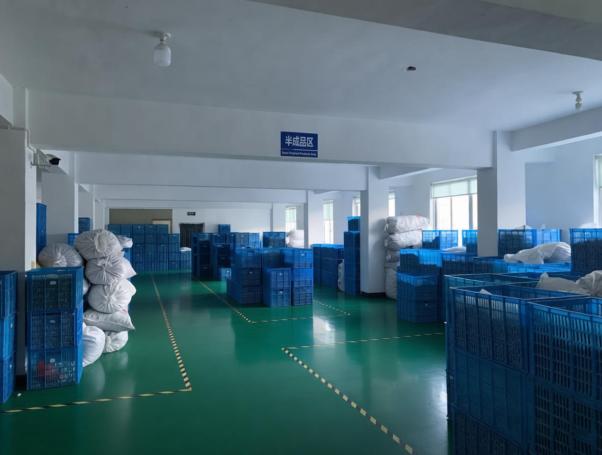
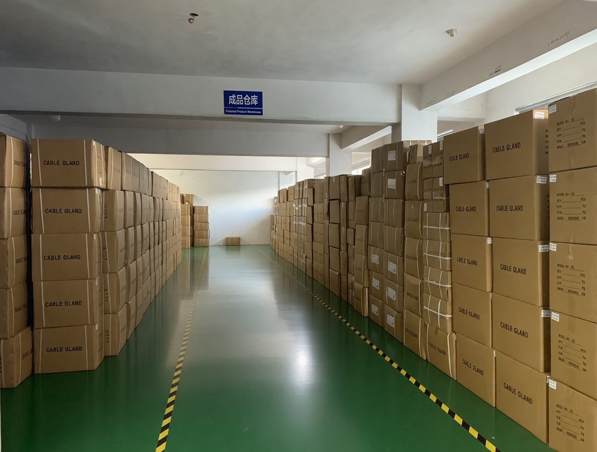
Confirm the thread and clamping-range combinations that will be held for your account, the packing format per size, and the replenishment interval at inquiry stage. Gutai operates a 5,000 m² facility with 80 employees, an annual output of 10,000,000 units and a 10-engineer team, with roughly 80% of output exported to the Middle East, Southeast Asia, India, Pakistan, the EU, the United Kingdom and the USA. Share your size mix and required delivery window through the contact details below to receive a quotation and a sample plan.
Next Step: Match a Gland to Your Drawing
Send the thread standard, thread outer diameter, panel wall thickness and measured cable jacket diameter, and the matching gland, junction box entry or MC4 connector can be confirmed against your drawing rather than a generic size chart.
Product range and specifications: gt-connector.com
Download the full catalogue: Gutai product catalogue (PDF)
Conclusion
Cable gland selection is a four-gate decision. The thread family and its outer diameter — 12–63 mm across M12–M63 and 12.5–59.3 mm across PG7–PG48 — fixes the panel. The thread length, 9–21 mm, fixes the wall. The cable clamping range, 3–45 mm overall, fixes the jacket entry. The service mode fixes the temperature limit at −20 °C to 80 °C dynamic or −40 °C to 100 °C static, and with it the Nylon PA66 and NBR material expectations. Certification — CE, RoHS, REACH, CCC, UL 514B, EN 62444:2013 and ISO 9001, with MC4 connectors under UL 514B File E539858 — confirms that the assembly you selected was actually tested as an assembly.
Resolve the gates in that order and the comparison at the end is short. Resolve them in a different order and the IP68 rating becomes a specification on paper rather than a property of the installed enclosure.
Have Questions or Need More Details?
Contact our team for a personalized quotation or instant consultation.
Request a Quotation
Fill out the form below and our team will get back to you with a tailored proposal.
WhatsApp Direct Chat
Prefer to chat in real-time? Message us on WhatsApp for instant assistance & quick answers.
- Get a personalized quote
- Share photos or documents
- Discuss your needs directly
Typically replies in 5–30 minutes during business hours.