
High-Vibration Industrial Panels: Solving CT Wiring Failures with DIN-Rail Current Transformers

DM-20 mini current transformer: a compact 0.66 kV DIN-rail CT with a 20 mm window, used where panel space and connection stability both matter.
Constant vibration is one of the least visible causes of current transformer failure inside an industrial control panel. The CT itself rarely fails electrically. The connection between the secondary winding and the field wiring does. Screw-clamp terminals back out under continuous machine vibration, the secondary circuit develops a high-resistance joint, and the current value reaching the meter, relay, or PLC begins to drift, spike, or drop to zero for no obvious reason.
A DIN-rail current transformer with a plug-in terminal design addresses that specific failure mode. The DX/DM current transformer from HEYI ELECTRICAL is a compact low-voltage current transformer rated 0.66 kV that mounts on DIN rail and terminates through a plug-in connection, so the secondary interface becomes a repeatable factory-defined contact rather than a field-tightened screw. This article explains the failure mechanism, the selection criteria that actually matter in a vibrating panel, and the installation steps that keep the secondary circuit stable over years of service.
Problem Definition: What a CT Wiring Failure Looks Like in a Vibrating Panel
A CT wiring failure is a degradation of the secondary circuit — terminal, conductor, or contact — that changes the measured current before the CT core itself has failed. In vibration-exposed panels it usually appears as a cluster of symptoms rather than a single event:
- Current readings that drift slowly over weeks, then return to normal after a terminal is re-tightened.
- Intermittent zero or near-zero current on one phase while the load is clearly present.
- Phase imbalance or power-factor alarms triggered by a single unstable input.
- Discoloration, warmth, or a faint smell at the CT terminal block.
- A torque check that finds a secondary screw below specification, or a conductor that moves when lightly pulled.
None of these symptoms is unique to vibration, which is why the problem is frequently misdiagnosed as a faulty meter, a failing CT, or a software scaling error. The distinguishing detail is repetition: the same terminal loosens again after it has already been re-torqued, and the same feeder misreads again after the panel has been in service for a few months.
Why the secondary side is the weak point
The primary conductor passes through the window and never touches the CT electrically. Everything that can fail mechanically sits on the secondary side: the clamp, the screw, the ferrule, the conductor strands, and the housing that holds them. A vibrating panel applies a small, continuous, high-cycle load to exactly those parts. A terminal that is correctly torqued at commissioning can still lose clamping force over time, and a stranded conductor clamped without a ferrule can lose strands progressively without any visible external change. The result is a high-resistance joint that behaves normally at low current and becomes unstable at rated current, which is why the fault so often appears only during peak load.
Industry Background: Why Low-Voltage Panels Are Getting Harder on Connections
Low-voltage distribution and control panels have become denser and more modular. Current transformers now share DIN rail space with digital meters, transmitters, relays, and terminal blocks, and they are frequently installed on panels that are bolted directly to equipment producing continuous vibration: generator sets, automatic transfer switch cabinets, compressor skids, and machine-mounted control enclosures. In these installations the CT is no longer a static instrument on a wall; it is a component on a moving structure.
At the same time, the measurement expectations have risen. Feeder monitoring, sub-metering, and relay protection all assume a stable secondary signal. A joint that adds even a small and variable resistance changes the burden seen by the CT and shifts the reading, which undermines exactly the energy and load data the panel was built to produce.
The applicable performance baseline is set by the instrument transformer standards. IEC 61869-2:2012 specifies additional requirements for newly manufactured inductive current transformers used with electrical measuring instruments and/or protective devices at rated frequencies from 15 Hz to 100 Hz. IEC 61869-10:2017 covers low-power passive current transformers with analogue output for measurement or protection in the same frequency range, and IEC 61869-14:2018 sets requirements for current transformers used in DC applications above 1.5 kV. These documents define accuracy, insulation, and test expectations; they do not replace the buyer's own verification of how a specific product is mechanically terminated and installed. That verification is where vibration-related failures are prevented.
Detailed Solution: The DX/DM DIN-Rail Current Transformer
HEYI ELECTRICAL (Wenzhou Heyi Electrical Co., Ltd.) is a China-based manufacturer of current transformers and current sensors, established in 2012. The company operates a 10,000 m² factory with 56 employees, an annual output of 356,000 units, and an R&D team of 5 engineers, and reports that 95% of its output is exported to markets including Southeast Asia, South Korea, Europe, South America, Australia, Africa, the Middle East, and North America.

The DX current transformer: compact low-voltage CT rated 0.66 kV, DIN-rail mounted, with a plug-in terminal interface instead of a screw-clamp secondary block.
The DX/DM model current transformer is a compact low-voltage CT rated 0.66 kV with DIN-rail mounting and a plug-in terminal design. Its relevance to vibration is structural rather than promotional: it removes the two features that most often degrade in a vibrating panel.
- Plug-in terminal instead of a field-tightened screw clamp. The secondary connection is made through a defined plug interface, so the contact is created by the connector geometry rather than by the torque a technician applies on site. Connection quality becomes repeatable across panels installed by different teams.
- DIN-rail mounting instead of free mounting. The CT is held by a rail latch rather than by its own terminal screws, so the mechanical fixing and the electrical connection are separated. Vibration load is carried by the rail and the latch, not by the current-carrying termination.
- Compact housing. A smaller, lower-mass body on the rail reduces the cantilever effect that amplifies panel vibration at the end of a heavier device.
- Secure terminal structure and flame-retardant housing design. The termination is designed to resist loosening, and the housing material is selected for flame-retardant behaviour.
- Temperature rise control. Contact heating is a leading indicator of a degrading joint; thermal behaviour is controlled during design and checked in production.
HEYI states that accuracy class can reach 0.5 or 0.2 depending on model, and that customized ratios such as 100/5A, 500/5A, 1000/5A, and 2000/5A are available. For a specific DX/DM variant, the ratio, class, and burden should be confirmed on the model datasheet before the panel drawing is released.
What is verified before the CT leaves the factory
HEYI's quality control includes 100% routine test, accuracy test, insulation resistance test, withstand voltage test, appearance inspection, and pre-shipment inspection. Production process control also covers accuracy calibration, polarity test, ratio test, temperature rise control, flame-retardant housing design, and a secure terminal structure, supported by incoming material inspection and clear wiring labelling. For a vibration-sensitive panel, these records matter because they establish the baseline that on-site commissioning checks can be compared against.
Step-by-Step Breakdown: Replacing a Vibration-Prone CT Connection
Step 1 — Characterise the vibration and the mounting point
Identify what the panel is mechanically attached to and whether the CT position sits on a structural member or on a bracket that amplifies movement. A feeder CT installed beside a generator or ATS mechanism experiences a different duty cycle from one installed in a static wall-mounted cabinet. This step decides whether a standard DIN-rail solution is sufficient or whether additional mechanical support is needed.
Step 2 — Confirm the electrical requirement before the housing
Fix the ratio, accuracy class, burden, and rated voltage first. The DX/DM range is rated 0.66 kV, which places it in low-voltage panel applications; accuracy class and ratio are model-dependent, and custom ratios can be specified. Selecting the housing before the electrical values is the most common cause of a late redesign, because a different ratio may require a different window size or body dimension.
Step 3 — Choose mounting and termination style
In a new panel, DIN-rail mounting with a plug-in terminal is the lower-risk choice for vibration duty because the mechanical and electrical interfaces are separated. In a retrofit where the primary cable cannot be disconnected, a split-core CT may be the practical option; HEYI notes that split-core models can reduce installation time by 50%–70% in retrofit projects and avoid cable disconnection, which also lowers shutdown and labour cost. The two decisions are independent: mounting style follows the panel, termination style follows the risk of loosening.
Step 4 — Prepare and strain-relieve the secondary wiring
Use ferrules on stranded conductors, keep the secondary conductor short and supported so that its weight is not carried by the CT terminal, and label each core clearly. HEYI provides clear wiring labelling and wiring guidance as part of its technical support, which reduces the wiring errors that later look like measurement faults. The goal is that no mechanical load from the cable reaches the contact.
Step 5 — Commission with checks that catch a bad joint
On site, verify polarity and ratio against the factory record, perform an insulation resistance check on the secondary circuit, and compare the CT reading with a clamp meter or a known load. A plug-in connection makes this faster because the interface can be reseated without re-terminating the conductor. Record the as-found values so that any later drift can be attributed to a specific joint rather than to the whole circuit.
Step 6 — Set a maintenance interval that matches the asset
For panels on continuously running machinery, add the CT secondary circuit to the routine inspection: visual check for discoloration, a light pull test on the connector, and a thermal scan of the terminal area under load. Overheating is a recognised risk in this application, and HEYI addresses it through temperature rise control in design and production; in service, thermal monitoring is the cheapest way to detect a degrading joint before it becomes an outage.
Use Cases: Where DIN-Rail CTs Solve the Vibration Problem
HEYI lists the applications best served by its current transformers as low-voltage switchgear, power distribution cabinets, energy metering systems, commercial buildings, industrial control panels, generator panels, ATS cabinets, feeder monitoring, relay protection systems, and utility power monitoring projects. Within that list, the vibration argument is strongest in four situations:
- Generator panels. Continuous rotational vibration plus high load current is the combination that most reliably exposes a weak secondary termination.
- ATS cabinets. Repeated transfer operations introduce mechanical shock in addition to steady vibration, which is hard on screw-clamped terminations.
- Industrial control panels on machine frames. Panel-mounted CTs share the machine's vibration spectrum, and feeder readings are used for load management and energy allocation.
- Feeder monitoring and relay protection circuits. A variable contact resistance changes the burden and therefore the signal that protection decisions depend on.
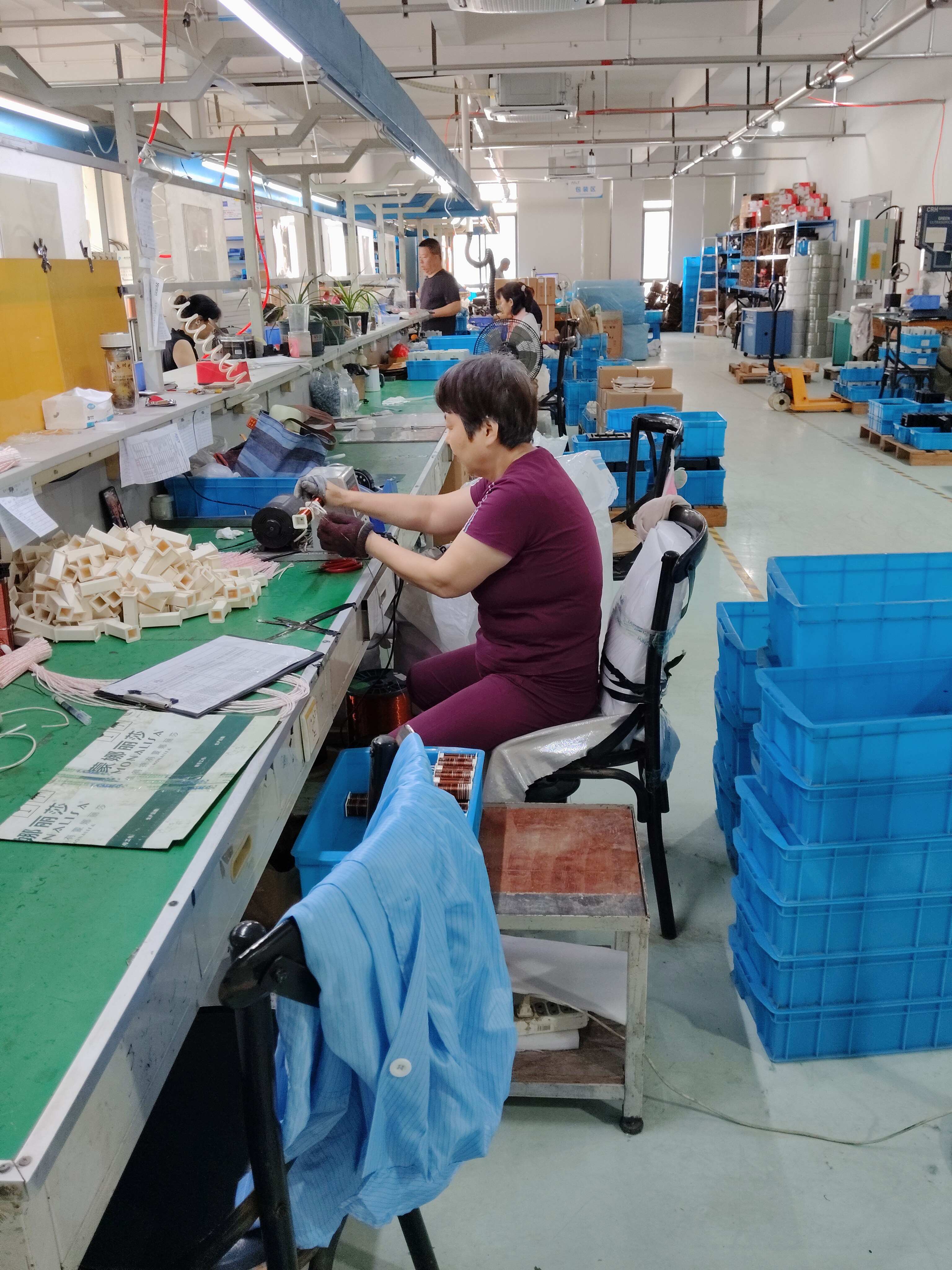
Assembly line at HEYI ELECTRICAL, where the DX/DM DIN-rail current transformer range is produced alongside split-core, solid-core, and three-phase CTs.
Comparison Table: Vibration-Related Failure Modes and Verification Points
The table below maps each failure mode to what a technician actually observes, the check that confirms it, and the corresponding control measure in HEYI's current transformer production. It is a verification tool, not a product ranking.
| Failure mode | What you observe in the panel | Verification point | HEYI control measure |
|---|---|---|---|
| Loosened secondary terminal | Drifting or intermittent current on one phase | Light pull test; re-torque history review | Secure terminal structure; plug-in terminal on DX/DM; DIN-rail mounting |
| Conductor damage at the clamp | Reading changes when the cable is moved | Inspect strands; confirm ferrules used | Clear wiring label; wiring guidance provided as technical support |
| CT migration on the rail | Window no longer centred on the primary conductor | Check rail latch engagement; verify window clearance | DIN-rail mounting; compact housing |
| Insulation stress | Discoloration; insulation resistance below expectation | Insulation resistance and withstand voltage records | 100% routine test including insulation resistance test and withstand voltage test |
| Thermal rise at the contact | Warm terminal; accuracy drift under load | Thermal scan under load; ambient and current check | Temperature rise control; flame-retardant housing design; thermal protection approach |
| Polarity or ratio error after rework | Meter reads reversed or on the wrong scale | Polarity and ratio check at commissioning | Polarity test, ratio test, accuracy calibration, accuracy test |
Sources: HEYI ELECTRICAL production and quality-control facts, HEYI risk-control documentation.
FAQ
Which standard applies to a 0.66 kV DIN-rail current transformer, and what evidence should I request?
For inductive low-voltage current transformers used with measuring instruments or protective devices at rated frequencies from 15 Hz to 100 Hz, the relevant baseline is IEC 61869-2:2012. Low-power passive current transformers with analogue output fall under IEC 61869-10:2017, and DC applications above 1.5 kV under IEC 61869-14:2018. Request model-specific evidence rather than a general certificate claim: accuracy test data, insulation resistance test, withstand voltage test, polarity and ratio verification, and the routine test record. HEYI's quality control covers 100% routine test, accuracy test, insulation resistance test, withstand voltage test, appearance inspection, and pre-shipment inspection, so these records are produced per unit rather than per batch.
Can a DIN-rail CT with a plug-in terminal really hold up in a high-vibration panel?
It removes the most common mechanical failure point, but it is not a substitute for correct installation. The plug-in terminal replaces a field-tightened screw clamp with a defined connector interface, and DIN-rail mounting separates the mechanical fixing from the electrical termination, so the current-carrying contact is no longer carrying the CT's own weight and vibration load. HEYI supports this with a secure terminal structure, flame-retardant housing design, and temperature rise control. In practice, the outcome still depends on strain relief on the secondary cable, correct ferrules, and a commissioning pull test. Where the panel experiences strong mechanical shock, add a periodic inspection interval rather than assuming the product alone solves it.
How do DIN-rail CTs compare on cost with low-cost generic current transformers?
HEYI states that its current transformers may have a slightly higher unit cost than low-cost generic CTs, but that they help reduce replacement cost, installation risk, measurement deviation, and project mismatch. In a vibration-exposed panel the relevant comparison is not the purchase price of one CT but the cost of a return visit, a re-termination, and the energy data that has to be reconstructed afterwards. For retrofit work, split-core models can reduce installation time by 50%–70% and avoid cable disconnection, which lowers shutdown and labour cost. Accuracy class can reach 0.5 or 0.2 depending on model, and customized ratios such as 100/5A, 500/5A, 1000/5A, and 2000/5A are available, so the specification can be matched to the meter rather than over- or under-specified.
What are the minimum order quantity, sample arrangement, and lead time?
The minimum order quantity is 1 unit, which allows a single DIN-rail CT to be tested in the actual panel before a larger release. Typical production lead time is 3–30 days, supported by a monthly production capacity of 20,000 units. Delivery terms are FOB, CIF, or EXW, and payment can be made by T/T, AliPay, Alibaba, or PayPal. Acceptance can be carried out by video or photographs, and sample confirmation is part of the process for customized orders, so the ratio, class, and terminal configuration are agreed before serial production.
How do I choose a long-term current transformer supply partner in China?
Test the supplier against continuity, not against a single quotation. The practical checklist is: verified monthly capacity and lead time, a stated quality-control sequence, engineering support during selection, and a documented route for replacement. HEYI ELECTRICAL runs a 10,000 m² factory with 56 employees, 5 engineers, a monthly production capacity of 20,000 units, and a typical lead time of 3–30 days, exporting 95% of output to Southeast Asia, South Korea, Europe, South America, Australia, Africa, the Middle East, and North America. Technical support includes wiring guidance, product replacement support, and online after-sales service — the three items that matter most when a panel is already on site. To evaluate the DX/DM DIN-rail range for a vibration-exposed panel, request a sample or a quotation at bethy@heyiele.com or WhatsApp +86 13968747975, and review the full catalogue before finalising the specification.
Conclusion
CT wiring failures in high-vibration panels are a mechanical problem that shows up as a measurement problem. The fix has three parts: separate the mechanical fixing from the electrical termination, make the secondary interface repeatable, and verify the result at commissioning and during service. A DIN-rail current transformer with a plug-in terminal — such as the 0.66 kV DX/DM model from HEYI ELECTRICAL — addresses the first two directly, while the third remains an installation discipline that no product can replace.
For buyers at the decision and execution stage, the useful next step is narrow rather than broad: take one problematic feeder, replace the screw-clamped connection with a DIN-rail plug-in CT of the same ratio and class, and compare the reading stability over a full load cycle. If the drift disappears, the specification is validated for the rest of the panel.
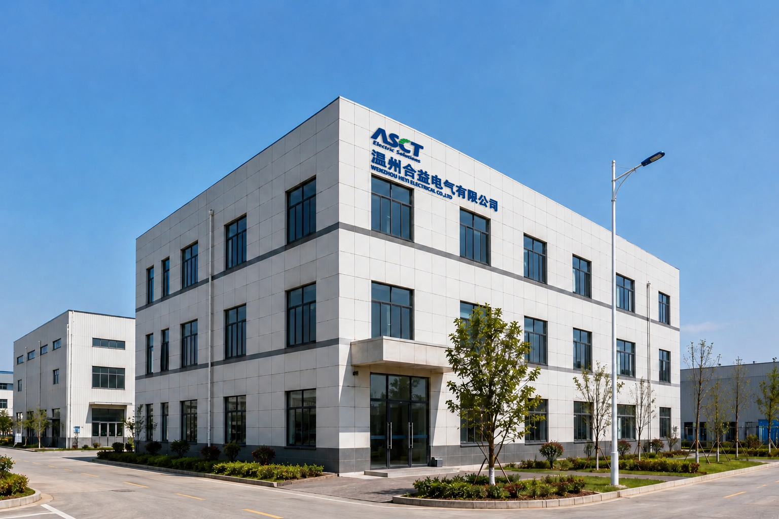
Next step: test the connection in your own panel
Request a DX/DM DIN-rail current transformer sample (MOQ 1 unit, lead time 3–30 days), or ask for a quotation matched to your ratio, accuracy class, and burden. Technical support covers wiring guidance, product replacement support, and online after-sales service.
Email: bethy@heyiele.com | Tel / WhatsApp: +86 13968747975 | Website: www.heyiele.com
Download the product catalogue: HEYI Electrical Product Catalogue (PDF)
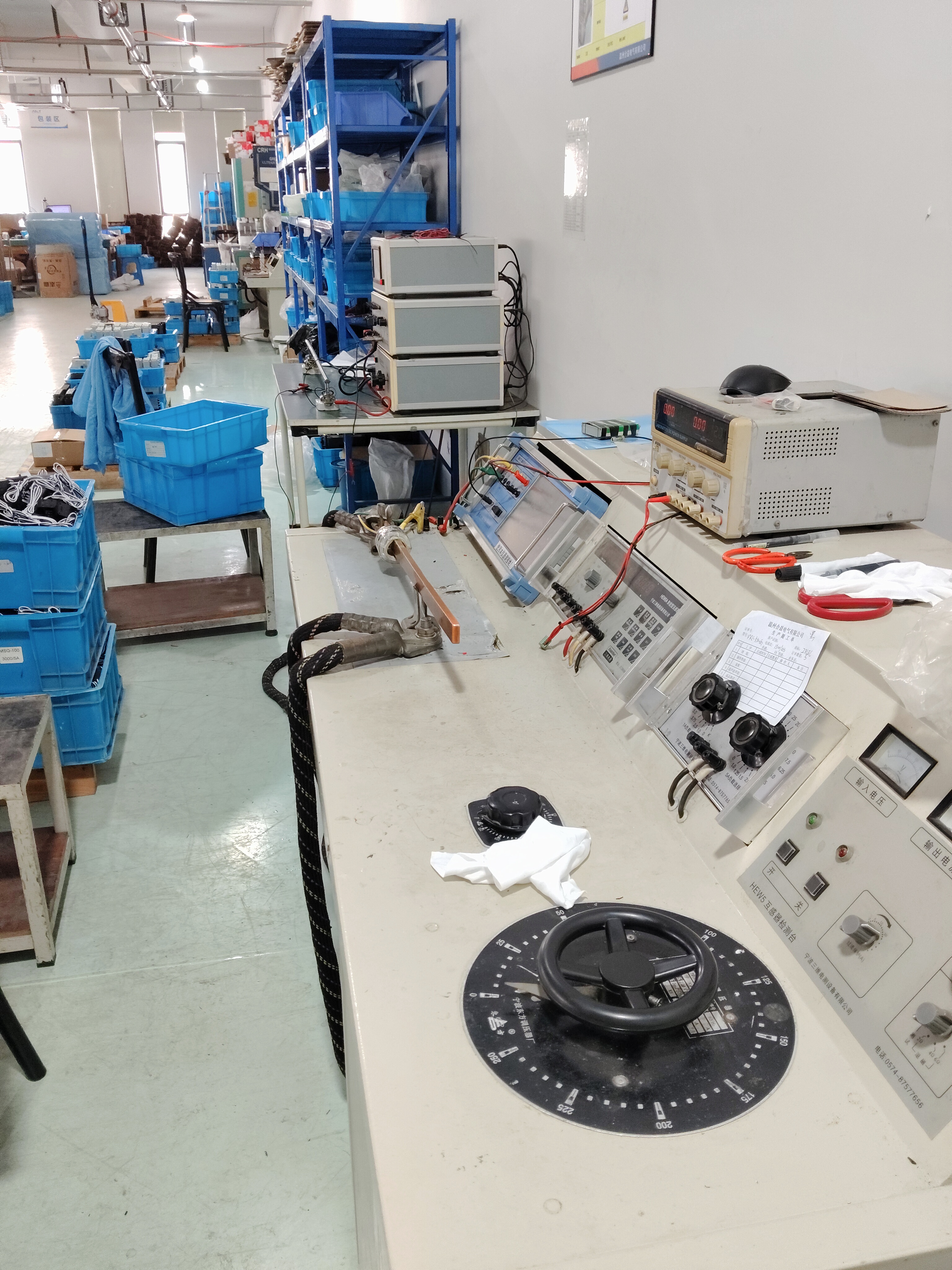
Every unit passes a 100% routine test, accuracy test, insulation resistance test, withstand voltage test, and appearance inspection before pre-shipment inspection.
Have Questions or Need More Details?
Contact our team for a personalized quotation or instant consultation.
Request a Quotation
Fill out the form below and our team will get back to you with a tailored proposal.
WhatsApp Direct Chat
Prefer to chat in real-time? Message us on WhatsApp for instant assistance & quick answers.
- Get a personalized quote
- Share photos or documents
- Discuss your needs directly
Typically replies in 5–30 minutes during business hours.