
How to Specify Hi-B Oriented Silicon Steel for UHV Transformer Cores: B8, P1.7/50 and Impurity Control
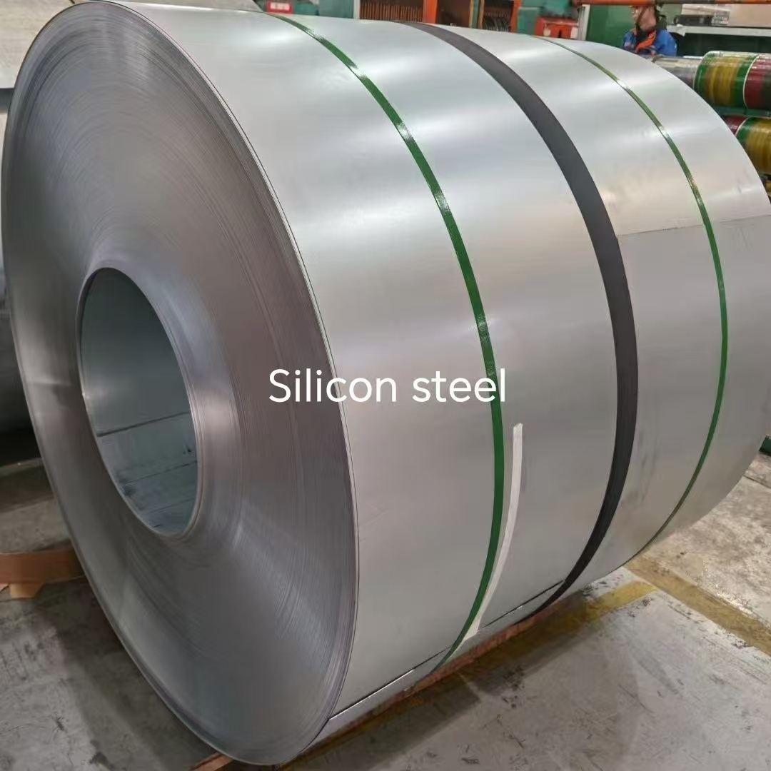
A UHV transformer core should be specified on three linked numbers, not one: flux density at 800 A/m (B8), specific total loss at 1.7 T and 50 Hz (P1.7/50), and nominal gauge. For UHV cores the practical Hi-B shortlist is 0.20 mm 20-65 at P1.7/50 ≤0.65 W/kg, 0.23 mm 23R075 at ≤0.75 W/kg, and the 0.27 mm 27Q095–27Q120 family at ≤0.95 W/kg to ≤1.20 W/kg — all at B8 ≥1.88 T, with selected grades reaching ≥1.91 T.
The two magnetic numbers answer different questions. B8 tells you how readily the steel magnetises. P1.7/50 tells you what it costs in watts to magnetise and reverse it. Gauge decides how much of that material you can physically fit into a core of a given diameter, and chemistry decides whether the numbers still hold after the coil has been slit, cut, stacked, annealed and energised for a decade.
This guide is written for the evaluation-to-execution stage: the point at which a transformer manufacturer or EPC buyer already knows the unit rating and now has to lock grade, gauge, coating and documentation before the purchase order. It explains what the two parameters actually measure, how the 0.20 mm, 0.23 mm and 0.27 mm families behave inside a real core, and which chemical controls belong in the specification text.
What B8 and P1.7/50 Actually Measure
Both parameters are measured in the rolling direction on standardised specimens. Neither is a property of the finished core; both are properties of the strip that the core is built from. That distinction drives most of the specification errors described later.
B8 — flux density at 800 A/m
B8 is the magnetic flux density, in tesla, reached when a specimen is magnetised under an applied field of 800 A/m. Because grain-oriented electrical steel is engineered around a Goss texture, with grains aligned close to {110}<001>, B8 works as a texture score: the higher the figure, the larger the share of grains oriented so that the easy magnetisation axis runs along the strip.
Hi-B material is defined by this band. B8 ≥1.88 T is the entry level for high-permeability grain-oriented grades, and selected grades are supplied at ≥1.91 T. Conventional CGO material generally does not reach the same band.
For a UHV unit, B8 governs three things that a loss figure does not: no-load exciting current, the flux margin available before saturation during energisation and load rejection, and the harmonic content of the magnetising current. A core specified only on loss can meet its guarantee at rated voltage and still misbehave under over-excitation.
P1.7/50 — specific total loss
P1.7/50 is specific total loss in W/kg at a peak flux density of 1.7 T and a frequency of 50 Hz, measured on Epstein strips or a single-sheet tester under the applicable IEC or ASTM method. The figure combines hysteresis and eddy-current loss and is the reference value behind a no-load loss guarantee.
It is also a fixed reference condition. A core that runs at a different peak flux density, or at 60 Hz, cannot be judged from P1.7/50 alone; the supplier has to provide data at the actual operating condition. RFQs that quote only a P1.7/50 ceiling and say nothing about operating flux are a common source of dispute after the heat run.
Problem Definition: Where UHV Core Grade Selection Usually Goes Wrong
Grade selection failures on UHV cores are rarely caused by buying the wrong brand. They are caused by specifying one parameter where three interlock. Five patterns account for most of them.
- Loss-only selection. A grade is chosen for a low P1.7/50 and its B8 is never written into the RFQ. The core passes the no-load loss test but draws more exciting current than the design assumed and leaves less margin under over-excitation.
- Comparing numbers from different test regimes. IEC and ASTM specifications are not interchangeable by label. ASTM A876-17e1 and IEC 60404-8-7:2020 must be compared grade by grade, not assumed equivalent.
- Ignoring the stacking-factor penalty of thin gauge. Thinner strip lowers specific loss per kilogram but adds insulation interfaces per unit of build height, so a core of the same window may need a larger diameter or more turns to carry the same flux.
- Treating chemistry as the mill's private business. Carbon, sulphur and nitrogen, plus the balance of the inhibitor system, determine whether loss drifts over service life and how much the core contributes to noise.
- Reading the grade name alone. The suffix carries process information. Without knowing what it means, buyers compare materials that were never equivalent.
Industry Background: How the Standards Frame Hi-B Material
IEC 60404-8-7:2020 defines grades of cold-rolled grain-oriented electrical steel strip and sheet delivered in the fully processed state, with nominal thicknesses of 0.20 mm, 0.23 mm, 0.27 mm, 0.30 mm and 0.35 mm. It sets general requirements, magnetic properties, geometric characteristics, tolerances and inspection procedures, and covers Goss-textured material supplied in the final-annealed condition in coils or sheets for the construction of magnetic circuits. All three grade families discussed here fall inside that scope.
Thinner material is handled elsewhere. IEC 60404-8-8:2017 defines the grades of thin grain-oriented electrical steel strip and sheet at nominal thicknesses of 0.05 mm, 0.10 mm, 0.15 mm and 0.18 mm, alongside thin non-oriented grades. A specification that creeps below 0.20 mm therefore changes its governing standard, which is one more reason to state thickness and standard together rather than thickness alone.
On the American side, ASTM A876-17e1 covers flat-rolled, grain-oriented, fully processed low-carbon silicon-iron electrical steels whose low core loss and high permeability in the direction of rolling are achieved by metallurgical processing, and describes the covered material as having a silicon content of approximately 3.2%. Test method choice matters too: IEC 60404-17:2021 applies to the measurement of magnetostriction characteristics of grain-oriented electrical steel strip and sheet under an applied AC magnetic field at 50 Hz or 60 Hz, which is the route to use when noise is a design constraint rather than an afterthought.
Demand context is worth noting at the specification stage. The global silicon steel market was valued at USD 31.55 billion in 2025 and is projected to reach USD 59.41 billion by 2035 according to Strategic Revenue Insights. High-grade grain-oriented capacity is the tightest part of that curve, which is why documentation quality and delivery reliability weigh as heavily as the catalogue figure in UHV procurement.
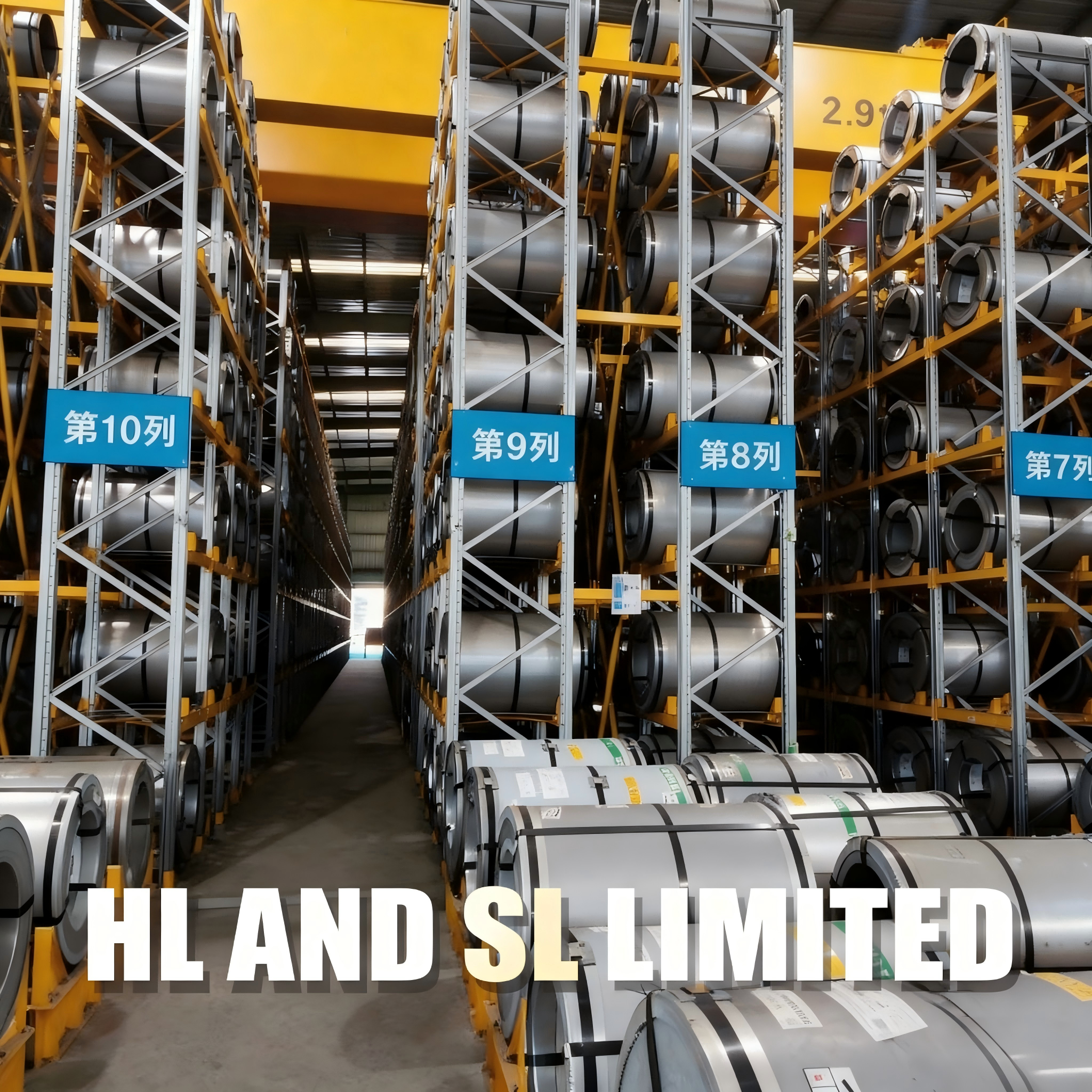
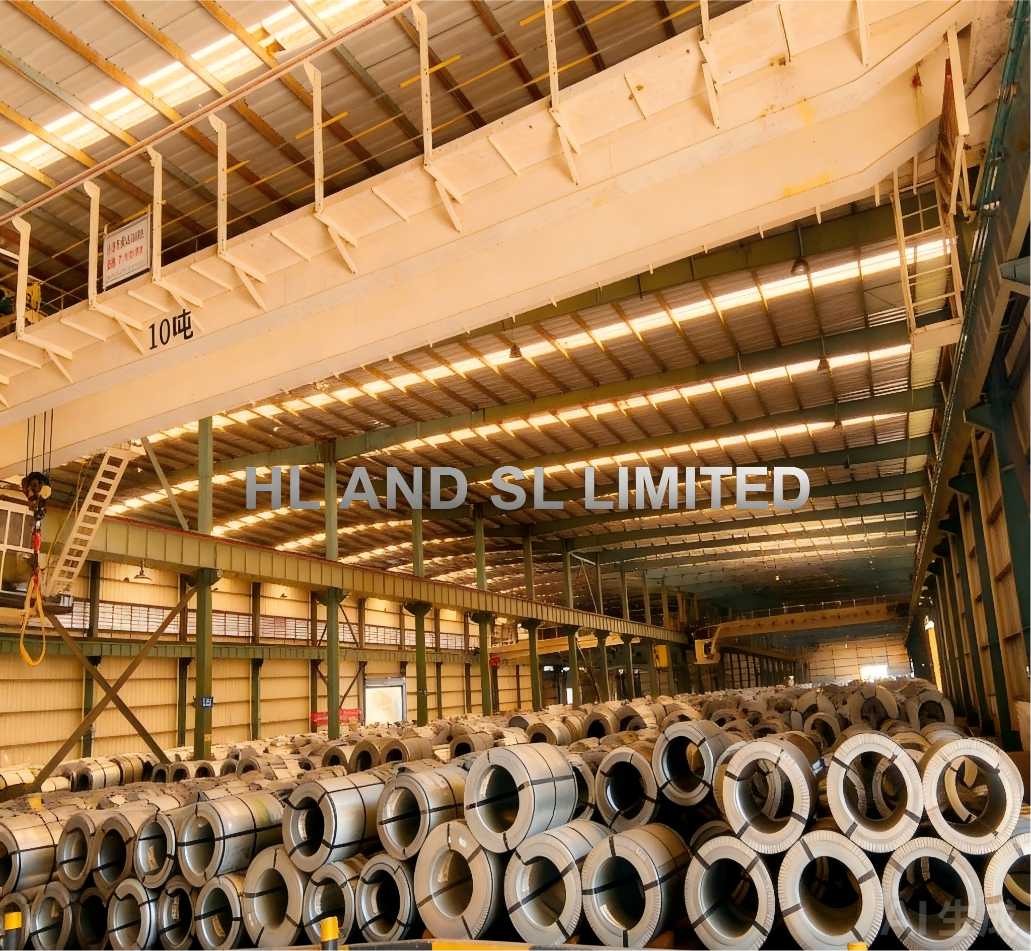
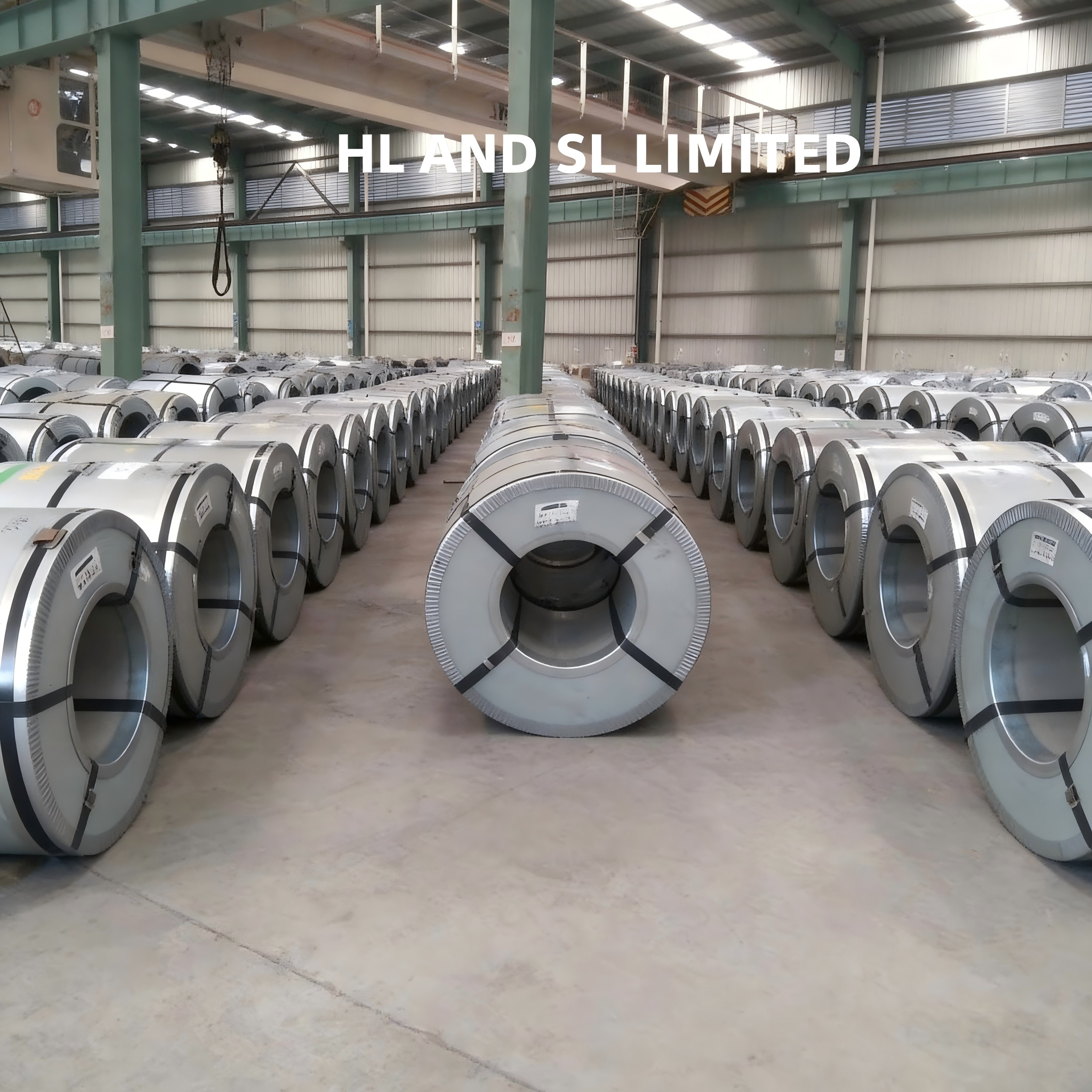
HL AND SL LIMITED is a China-based electrical steel supplier and exporter, founded in 2012, operating a 30,000 m² processing plant with annual output of 30,000 T and roughly 80% of volume exported to markets including Mexico, Brazil, Italy, the UAE and India. The company is an authorized agent of China Baowu Steel Group and reports that it ranks among China's top three electrical steel exporters. Its oriented range covers CGO, Hi-B, laser-engraved R series and heat-resistant HS series material, with thickness customization from 0.18 mm to 0.35 mm and widths typically 800–1250 mm.
The Three Hi-B Grade Families for UHV Cores
Each family is a different answer to the same question: how much loss can be removed per kilogram, and what does removing it cost in build height, labour and price. None of the three is universally better.
0.20 mm 20-65 — P1.7/50 ≤0.65 W/kg
The 0.20 mm 20-65 grade delivers the lowest specific total loss in this set at ≤0.65 W/kg. It is the grade to select when loss capitalisation is the dominant term in the total owning cost calculation — typically the largest UHV units, where every watt of no-load loss is valued over a twenty- to thirty-year service life and where the loss evaluation rate is set high by the tender.
Its costs are structural, not commercial. A 0.20 mm core needs more laminations for the same build height, carries a higher share of insulation coating per unit of magnetic cross-section, and is more sensitive to burr height, edge damage and handling during stacking. Slitting and cut-to-length yield per ton is lower than at 0.27 mm. The grade pays back only when the loss valuation is high enough to amortise that processing burden.
0.23 mm 23R075 — P1.7/50 ≤0.75 W/kg
The 0.23 mm 23R075 is the balanced choice and the most common default for UHV and EHV cores where loss capitalisation is significant but not extreme. In HL AND SL LIMITED's grade naming, the R series denotes laser-engraved material, in which the domain structure is refined to reduce loss in the rolling direction.
Two specification notes apply. First, the laser-refined effect is a surface condition and has to be treated as such: if the core will be stress-relief annealed after cutting, confirm with the supplier that the surface treatment is compatible, and consider the heat-resistant engraved HS series, which exists precisely for that route. Second, 23R075 should be compared with 20-65 on a full-core basis, including the stacking-factor difference, not on the W/kg figure alone.
0.27 mm 27Q095–27Q120 — P1.7/50 ≤0.95 W/kg to ≤1.20 W/kg
The 0.27 mm family spans a loss band from ≤0.95 W/kg at 27Q095 to ≤1.20 W/kg at 27Q120, with intermediate grades such as 27Q100, 27Q105 and 27Q110 sitting between those limits. Grade designations track the specified loss ceiling, so the choice inside the family is a straight trade between loss budget and price at constant gauge.
This gauge is the practical answer when stacking factor, mechanical robustness and cost dominate: large limb diameters, high kVA per limb, heavy handling in the stacking shop, or designs where the loss evaluation rate is moderate. 27Q095 is specified when a tight loss budget must still be met at 0.27 mm; 27Q120 is specified when the loss ceiling is generous and the priority is cost per ton and build reliability.
B8 ≥1.88 T, with selected grades at ≥1.91 T
All three families are specified at B8 ≥1.88 T as the Hi-B floor. Selected grades are supplied at ≥1.91 T. The distinction matters on a UHV core for three reasons: exciting current falls as B8 rises, the flux margin available during energisation inrush and load rejection widens, and the magnetising current waveform becomes less distorted. On very large units, that margin is a design case, not a comfort factor. Because B8 is quoted per grade and per heat, the actual value should be confirmed on the mill test certificate rather than inferred from the family name.
Thickness Trade-Offs: Loss, Stacking Factor and Handling
Reducing gauge lowers the eddy-current contribution to loss, which is why 0.20 mm 20-65 reaches ≤0.65 W/kg while 27Q120 sits at ≤1.20 W/kg. But a core is not a kilogram of steel; it is a stack with a fixed window. Three penalties scale with thinner material.
- Stacking factor. More laminations per unit height means more coating interfaces. The magnetic cross-section available inside the same core circle falls, so the designer has to recover the flux elsewhere — a larger diameter, a taller window or more turns.
- Cutting and stacking labour. Lamination count rises roughly in inverse proportion to gauge. Shear time, burr control, varnish or insulation handling and stacking hours all rise with it.
- Handling sensitivity. Thin strip buckles and work-hardens more readily. Burr and edge stress raise local loss, and the gain quoted on the certificate can be partly consumed in the cutting shop.
The reverse holds at 0.27 mm: fewer laminations, a better stacking factor, more tolerance to handling, and a lower price per ton — at the cost of a higher loss ceiling. The correct decision rule is to compare full-core no-load loss and full-core cost at the design flux, not to compare W/kg values from a datasheet.
Decision rule. If the tender values no-load loss at a high rate over the unit life, 0.20 mm 20-65 wins on total owning cost. If the loss rate is moderate and stacking factor and schedule matter, 0.23 mm 23R075 is the default. If the design is loss-tolerant, handling-heavy or cost-driven, choose inside the 0.27 mm 27Q095–27Q120 band and set the ceiling to the design, not to the catalogue.
Silicon Content, Inhibitors and Impurity Control
Magnetic properties of grain-oriented silicon steel are decided in the steelmaking and annealing stages, long before a core is stacked. Three chemical themes belong in the specification.
Silicon content around 3.0%–3.2%
Silicon raises the electrical resistivity of the alloy, which suppresses eddy-current loss, and it stabilises the body-centred cubic structure needed for good texture. The practical window for grain-oriented grades sits around 3.0%–3.2%; ASTM A876-17e1 describes its covered material as having approximately 3.2% silicon. Pushing silicon higher narrows the rolling and annealing window and increases brittleness, so the composition has to be balanced against process yield, not maximised. Buyers should ask for the heat analysis alongside the magnetic test report rather than assume the range.
Inhibitor elements: MnS and AlN
Goss texture is not produced by rolling alone. It depends on inhibitor elements — manganese sulphide and aluminium nitride being the classical systems — that pin normal grain growth during secondary recrystallisation and allow a small number of favourably oriented grains to grow at the expense of the rest. The result is the large-grain, sharply oriented structure that produces B8 ≥1.88 T and the low loss figures quoted for Hi-B grades.
Inhibitors cut both ways. They must be present and correctly balanced during processing, and their residues must be controlled afterwards, because retained inclusions and precipitates raise loss and magnetostriction. This is why an experienced buyer asks how the inhibitor system is handled through final annealing, not only whether it exists.
Carbon, sulphur and nitrogen
Impurity control is where a certificate can look clean and a core can still drift. Carbon, sulphur and nitrogen each affect the finished magnetic behaviour:
- Carbon must be reduced during final decarburising annealing. Residual carbon promotes carbide precipitation and magnetic aging — loss creeping upward over years in service, which a factory acceptance test will not reveal.
- Sulphur participates directly in the sulphide inhibitor system and also ties up manganese. Off-target sulphur shifts the inhibitor balance and can move grain size and loss away from the intended grade.
- Nitrogen forms nitrides and, in free form, contributes to aging in the same way as carbon. Tight nitrogen control is part of holding the specified loss band rather than drifting within tolerance.
The practical requirement is a final product analysis per batch, issued with the material certificate, showing carbon, sulphur and nitrogen within the supplier's declared limits together with the silicon range. That converts chemistry from a claim into a documented, auditable fact.
Step-by-Step: Building the UHV Core Grade Specification
- Fix the electrical duty first. Record the maximum operating peak flux density, the over-excitation case, the system frequency and the loss evaluation rate that the tender applies. Every later choice is downstream of these four items.
- Set the B8 floor. Write B8 ≥1.88 T as the minimum, and raise it to the ≥1.91 T band where over-excitation margin or exciting current is a design constraint. Never leave B8 unstated.
- Set the P1.7/50 ceiling and name its reference condition. State that the ceiling applies at 1.7 T and 50 Hz, and require supplier data at the actual operating flux and frequency for verification.
- Choose gauge against the core, not the datasheet. Compare 0.20 mm, 0.23 mm and 0.27 mm at the design diameter and window, including stacking factor and lamination count.
- Write standard, grade and delivery state into the RFQ. Name IEC 60404-8-7:2020 or ASTM A876-17e1 explicitly, plus the grade designation and the fully processed final-annealed condition.
- Specify the coating. Organic coatings suit service temperatures up to about 180°C, inorganic coatings are used where resistance up to 800°C is required, and semi-organic systems sit between them. Coating choice interacts with stacking factor and with any post-cutting anneal.
- Specify the chemical documentation. Require silicon in the 3.0%–3.2% band, declared limits for carbon, sulphur and nitrogen, and a statement of the inhibitor route used to develop the Goss texture.
- Specify inspection, packing and logistics. Agree pre-shipment testing, third-party testing where the project requires it, batch certificates, export sea-worthy packing, and the delivery schedule against the core building plan.
Use Cases
UHV and EHV power transformer cores
Large power transformer cores carry the strongest loss capitalisation and therefore the clearest case for 0.20 mm 20-65 or 0.23 mm 23R075. In North America, oriented silicon steel from this supply chain has been used for more than ten years in manufacturing iron cores for power transformers, converter transformers and special engineering transformers, at an annual business scale of approximately USD 500 million through batch supply.
Converter transformer cores
Converter transformers combine AC and DC stress with harmonic-rich flux, which makes the B8 margin and the loss ceiling more critical than on a plain grid transformer. Here the ≥1.91 T band and a documented impurity profile are worth specifying, because harmonic content amplifies both loss and noise.
High-efficiency distribution transformers
Where grid energy-efficiency rules set the ceiling on no-load loss, 0.23 mm and 0.27 mm grades usually carry the volume. In Brazil, WEG has used oriented silicon steel for over ten years in large-scale power and distribution transformer production, supporting compliance with local grid energy-efficiency and low-carbon requirements; a representative office in Brazil provides localised technical service and supply-chain support for Latin America.
Reactor and noise-critical cores
Reactors and any core where sound pressure is a contractual limit need magnetostriction treated as a specification item. IEC 60404-17:2021 defines the measurement of magnetostriction characteristics under an applied AC field at 50 Hz or 60 Hz, and a supplier test report aligned to that method is the defensible way to qualify material for noise-critical duty.
Comparison Table: Hi-B Oriented Grades for UHV Cores
| Grade | Nominal thickness | P1.7/50 (max) | B8 (min) | Where it fits in a UHV core |
|---|---|---|---|---|
| 20-65 | 0.20 mm | ≤0.65 W/kg | ≥1.88 T | Highest loss capitalisation; largest UHV units where total owning cost is dominated by no-load loss |
| 23R075 | 0.23 mm | ≤0.75 W/kg | ≥1.88 T | Balanced UHV and EHV cores; laser-engraved surface; default when loss value is significant but not extreme |
| 27Q095 | 0.27 mm | ≤0.95 W/kg | ≥1.88 T | Thick-gauge cores that still carry a tight loss budget; strong stacking factor and handling tolerance |
| 27Q100–27Q110 | 0.27 mm | Between ≤0.95 and ≤1.20 W/kg | ≥1.88 T | Mid-band selection where loss, price and robustness are traded within one gauge |
| 27Q120 | 0.27 mm | ≤1.20 W/kg | ≥1.88 T | Cost-driven cores, large builds and handling-heavy shops; economical end of the 0.27 mm band |
P1.7/50 is the maximum specific total loss at 1.7 T and 50 Hz; B8 is the minimum flux density at 800 A/m. Selected Hi-B grades are available at B8 ≥1.91 T — confirm the actual value per grade and per heat on the mill test certificate. Thickness from 0.18 mm to 0.35 mm and widths typically 800–1250 mm are available as customized specifications.
Frequently Asked Questions
Which standard should a UHV core specification reference for Hi-B oriented silicon steel?
Reference the standard that matches the delivery state and thickness. IEC 60404-8-7:2020 covers cold-rolled grain-oriented electrical steel strip and sheet in the fully processed state at nominal thicknesses of 0.20 mm, 0.23 mm, 0.27 mm, 0.30 mm and 0.35 mm, including magnetic properties, tolerances and inspection procedures. ASTM A876-17e1 covers flat-rolled, grain-oriented, fully processed low-carbon silicon-iron electrical steels and describes its material as having approximately 3.2% silicon. Below 0.20 mm, thin grain-oriented grades fall under IEC 60404-8-8:2017. The two systems are not automatically equivalent, so the RFQ should name the standard, grade, gauge, B8 minimum, P1.7/50 maximum, coating type and delivery state, and require a grade-by-grade comparison where a tender cites the other system. For EU-bound projects, add a RoHS (2011/65/EU) declaration covering the coating system to the documentation package.
Can 0.20 mm material hold P1.7/50 ≤0.65 W/kg and B8 ≥1.88 T at the same time?
Yes. The 0.20 mm 20-65 grade is specified at P1.7/50 ≤0.65 W/kg with the Hi-B B8 floor of ≥1.88 T, and selected grades reach ≥1.91 T. The capability question is not whether the combination exists but whether it can be delivered at scale and documented per batch. The oriented range covers CGO, Hi-B, laser-engraved R series and heat-resistant HS series material in thicknesses from 0.18 mm to 0.35 mm and widths typically 800–1250 mm, with OEM and ODM production services, monthly capacity of 4000 T and a minimum order quantity of 25 T. Because B8 and loss are quoted per heat, the combination should be confirmed on the mill test certificate for each lot rather than assumed from the grade name.
What drives the cost difference between 0.20 mm, 0.23 mm and 0.27 mm grades?
Three factors, and only one of them is visible on a price list. Thinner gauge requires more rolling work and yields fewer tons per hour of processing, which raises cost per ton. It also raises cost per core: lamination count rises, more insulation interfaces reduce stacking factor, and more shear and stacking labour is consumed. Against that, thinner material lowers no-load loss, so the effective cost depends on how the project values each watt of loss over the unit life. The cheapest price per ton is therefore frequently not the cheapest core. Commercial terms in this supply chain are a 25 T minimum order quantity, EXW, FOB or CIF delivery terms, and 30/70 payment terms, which allows the loss-versus-price comparison to be run on the same commercial basis for all three gauges.
How should a buyer validate a Hi-B grade before committing to a full order?
Build the validation into the acceptance clause rather than leaving it to inspection on arrival. The stated acceptance routes are pre-shipment testing and third-party testing, with CMA/CNAS laboratories used for submission testing, and a batch inspection report supplied with the goods alongside the material certificate. Ask for the final product analysis covering silicon in the 3.0%–3.2% band together with the declared limits for carbon, sulphur and nitrogen, so that the impurity control behind the loss figure is visible. Where noise is a contractual limit, add a magnetostriction test report aligned to IEC 60404-17:2021. Confirm the coating type at the same time, since organic coatings are rated for service temperatures up to about 180°C, inorganic coatings up to 800°C, and the choice affects both stacking and any post-cutting anneal.
What lead time should be planned for Hi-B oriented silicon steel?
For regular orders the typical production lead time is 15–20 days. Urgent or stock orders can ship in 3–7 days, bulk export orders typically reach port in 30–45 days, and production after a letter of credit is established runs 7–30 working days. Monthly capacity of 4000 T against a 25 T minimum order quantity means a UHV core programme can be scheduled in staged lots rather than one blocked shipment. To move from specification to quotation, send the grade, gauge, B8 minimum, P1.7/50 maximum, width, coating and required delivery date to sales-01@hlslind.com or WhatsApp +86 134-6700-2282, and the matching lot plan can be confirmed against the core building schedule.
Conclusion
Hi-B oriented silicon steel for a UHV transformer core is not selected by picking the lowest loss figure on a catalogue page. It is selected by fixing B8, P1.7/50 and gauge together against the actual electrical duty, then defending that combination with chemical documentation and a defined acceptance route. The 0.20 mm 20-65 grade at ≤0.65 W/kg earns its place where loss capitalisation is high; 0.23 mm 23R075 at ≤0.75 W/kg is the balanced default; and the 0.27 mm 27Q095–27Q120 band covers the range from ≤0.95 to ≤1.20 W/kg where stacking factor, handling and cost carry more weight than the last fraction of a watt.
Whatever the gauge, the B8 floor of ≥1.88 T — with selected grades at ≥1.91 T — belongs in the specification, because it governs exciting current and over-excitation margin in a way that loss never will. And behind all of it sits chemistry: silicon around 3.0%–3.2%, an inhibitor system based on manganese sulphide and aluminium nitride that builds the Goss texture, and disciplined control of carbon, sulphur and nitrogen so that the loss figure quoted at dispatch is still the loss figure after a decade in service.
Request a Hi-B grade quotation or material sample
Share your grade, gauge, B8 minimum, P1.7/50 maximum, strip width and required delivery date, and HL AND SL LIMITED will confirm lot availability, coating options and the documentation package against your core building plan.
Email: sales-01@hlslind.com | Tel / WhatsApp: +86 134-6700-2282
Website: www.hlslind.com
Address: Shantou Qingyuncheng, Jiankang South Street, Jinyuan District, Taiyuan City, Shanxi Province, China
Download the product catalogue: HL AND SL LIMITED brochure (PDF)
Have Questions or Need More Details?
Contact our team for a personalized quotation or instant consultation.
Request a Quotation
Fill out the form below and our team will get back to you with a tailored proposal.
WhatsApp Direct Chat
Prefer to chat in real-time? Message us on WhatsApp for instant assistance & quick answers.
- Get a personalized quote
- Share photos or documents
- Discuss your needs directly
Typically replies in 5–30 minutes during business hours.