
High-Speed Bunching/Stranding Machine Application Guide: Matching Wire and Project Scenario to Acceptance Criteria
A high-speed bunching/stranding machine is defined less by the highest line speed printed in a catalogue than by the wire it is asked to run and the project it must fit into. Before requesting a quotation, a buyer should write down the project scenario — single-wire material and diameter, number of wires, bare or plated condition, required lay direction and lay length, pay-off and take-up form, spool specification, and the products that sit upstream and downstream — and then convert that scenario into measurable purchasing terms and into acceptance criteria that can actually be tested at factory acceptance and on site.
What the Problem Actually Is
Most sourcing errors in this equipment category do not come from a bad machine. They come from a scenario that was never written down. When buyers compare suppliers using a general catalogue, a headline speed figure or a unit price, they compress several very different projects into one specification. The result is a machine that runs, but does not fit the job: the pay-off format does not suit the incoming wire, the take-up spool does not match the plant’s handling, the lay length cannot be held on the conductor structure that matters, or the interface with the drawing or plating line behind it was never defined.
The application-first approach fixes this by reversing the order of the conversation. Instead of asking what a machine can do, the buyer first states what the project needs, then asks the supplier to confirm a configuration against that statement in writing. Purchasing terms become the record of that confirmation, and acceptance criteria become the test that the confirmation was accurate.
Industry Background: Why Stranding Scenarios Have Become More Specific
Bunching and stranding sit between conductor drawing or plating and the extrusion or cabling stage. Whatever comes out of the upstream process arrives at the stranding machine as an input, so upstream choices propagate directly into stranding requirements. A plant that draws its own wire, plates its own single wire, or runs a combined conductor line has already fixed much of the stranding scenario before the machine is even discussed.
HONTA was established in September 2006 and has long been committed to the research of cable conductor drawing and stranding technology. Its product scope includes copper and aluminum RBD lines, electrolytic plating lines, multi-wire drawing lines and high-speed stranding equipment, and the company established its second production base, HONTA INC., in the United States in 2017. HONTA describes its equipment as being built around high speed, efficiency, automation and humanized operation, and positions itself as a cable equipment system service provider rather than a single-machine vendor.
That system position matters for this guide, because it means the stranding machine is never evaluated in isolation. Where the conductor is drawn, plated and stranded inside coordinated equipment, the application question becomes an interface question: does the stranding configuration accept the wire the upstream line produces, in the spool format that line delivers it, at the pace the overall line is planned around?
The Application Matching Framework
Matching a high-speed bunching/stranding machine to a project is a five-dimension exercise. Each dimension must be answered before a technical data sheet can be frozen.
1. The Wire Dimension
- Single-wire material: copper or aluminum.
- Single-wire diameter or diameter range intended for the order.
- Number of wires per conductor, and whether the count is fixed or expected to vary across the product mix.
- Bare or plated single wire — plated conductors, such as nickel, silver or tin electroplated single wire produced on an electrolytic single wire plating line, introduce handling requirements that differ from bare copper.
- Finished conductor construction, including the outer diameter and how the lay is expected to look in cross-section.
2. The Process Dimension
- Required lay direction and lay length for each product in scope.
- How tightly the lay length must be held across a full spool, and what the buyer will measure to prove it.
- Whether the process needs a single twist or double twist configuration, which is a structural choice rather than a speed choice.
- Tension behaviour expected during acceleration, deceleration and spool changes.
3. The Handling Dimension
- Pay-off form: single spool, multi-wire pay-off, or motorised pay-off, matched to how the incoming wire is delivered.
- Take-up form: single spooler or double spooler, matched to downstream handling and changeover expectations.
- Spool specification, including flange and barrel dimensions and the resulting coil weight, which must be agreed as a contract item rather than assumed.
4. The Integration Dimension
- What sits immediately upstream — a multi-wire drawing line, a rod breakdown line, or an electrolytic plating line.
- Whether the stranding machine is a standalone unit or the final stage of an integrated conductor line.
- Interface points that must be fixed in writing: wire delivery height, spool transfer method, electrical supply convention, control handshake and fault signalling.
5. The Acceptance Dimension
- Which properties are measured at the factory before shipment, and which are measured on site after installation.
- Who performs each measurement, with what instrument, and against which agreed value or drawing.
- What happens when a measured value falls outside the agreed range — rework, replacement, or a documented concession.
Step-by-Step: Turning a Scenario into a Purchase Order
Step 1 — Write the conductor specification table first
List every conductor the machine is expected to run, and for each one record material, single-wire diameter, wire count, plated or bare condition, lay direction, lay length and finished outer diameter. This table is the single most useful document in the whole procurement process, because it converts an opinion about suitability into a comparison against stated inputs.
Step 2 — Record the plant reality around the machine
Floor space, spool storage, crane or lifting capability, upstream equipment model and downstream take-up all constrain the configuration. A motorised pay-off that cannot be loaded with the plant’s spools is a mismatch regardless of its engineering quality.
Step 3 — Ask for a configuration confirmation, not a brochure
Send the conductor table and the plant constraints to each candidate supplier and request a written response that states the proposed configuration, the pay-off and take-up format, and any conductor in the table the proposed machine would not cover. The exceptions list is as important as the confirmation, because it is where scope misunderstandings normally hide.
Step 4 — Convert the confirmation into purchasing terms
Every confirmed element should reappear as a numbered clause: conductor range, wire count, lay length range, lay direction, spool specification, pay-off type, take-up type, control interface, documentation, training, spare parts list and warranty scope. Terms written as adjectives cannot be verified; terms written as numbers, drawing references or named components can.
Step 5 — Set acceptance criteria against the terms
For each clause, define the evidence that closes it. Structural criteria (lay length, lay direction, wire count, outer diameter) are usually verified on samples. Electrical criteria are verified on conductor samples using the applicable test method agreed in the contract. Visual criteria cover surface condition, broken single wires, plated-layer continuity on plated conductors, and spool winding quality. Operational criteria cover run stability across the specified speed profile, tension behaviour during acceleration and spool change, and the response of the machine to a stop signal.
Step 6 — Agree the factory and site split
Decide in advance which tests happen before shipment and which happen after installation. Factory acceptance should cover what can only be proven with the machine running on the buyer’s wire; site acceptance should cover installation-dependent behaviour such as line integration, spool handling and operator interaction. A single combined acceptance event tends to leave interface problems to the very end.
Step 7 — Freeze the data sheet and control changes
After the purchase order is placed, treat the approved technical data sheet as the controlling document. Any later change to conductor range, spool size or interface should be raised as a written deviation with its own acceptance consequence, not absorbed informally during a site visit.
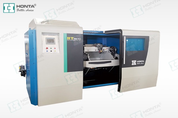
Use Cases: Four Scenarios, Four Different Priorities
Scenario A — Fine single wire, high wire count, soft conductor
When the conductor is built from many fine wires, the dominant risks are tension uniformity and wire breakage rather than throughput. The priority inputs are the wire count, the pay-off arrangement that can deliver that many wires without crossing or dragging, and the sensitivity of the stop response. Acceptance should focus on lay length consistency along the spool, the absence of broken or crossed single wires, and the surface condition of the finished conductor.
Scenario B — Plated single wire conductor
Where the conductor is built from nickel, silver or tin electroplated single wire produced on an electrolytic plating line, the stranding machine inherits a surface that must not be damaged. Handling becomes the central question: pay-off routing, contact points, tension limits and guide condition. Acceptance criteria should include a visual check of plated-layer continuity after stranding, agreed with the supplier before the order, because damage introduced at stranding is difficult to separate from plating defects afterwards.
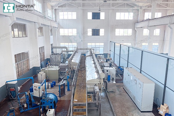
Scenario C — Larger cross-section conductor with long production runs
With larger conductors, spool capacity and changeover rhythm drive the economics more than fine-wire handling does. The priority inputs are spool specification, take-up capability, coil weight against the plant’s lifting equipment, and the length measurement method used to close out a production run. Acceptance should confirm spool winding quality, length accuracy against the agreed measurement method, and stable take-up behaviour across a full spool.
Scenario D — Stranding as the final stage of an integrated conductor line
When the stranding machine follows a rod breakdown line, a multi-wire drawing line or a plating line, the project is really a line-integration project. The priority inputs are delivery height, spool transfer, control handshake and fault propagation between stages. Acceptance should test the interface deliberately — a planned stop and restart of the upstream stage, a simulated fault, and a spool change — rather than assuming the interface will behave because each unit passed its own test.
Scenario-to-Acceptance Comparison
The table below summarises how the same machine category produces different clarification questions, different purchasing terms and different acceptance evidence depending on the project scenario.
| Project scenario | What must be clarified before quotation | What becomes a purchasing term | What proves acceptance |
|---|---|---|---|
| Fine single wire, high wire count, soft conductor | Wire count, single-wire diameter range, pay-off arrangement, stop response requirement | Conductor range table, pay-off type, tension control method, stop behaviour | Lay length consistency along the spool, no broken or crossed wires, surface condition |
| Plated single wire conductor (Ni, Ag or Sn plating) | Plating type, incoming surface condition, pay-off routing, guide material and condition | Handling specification, guide and contact-point requirements, agreed visual criteria | Plated-layer continuity after stranding, absence of scoring or burnishing marks |
| Larger cross-section conductor, long runs | Spool specification, coil weight, lifting capability, length measurement method | Take-up type, spool dimensions, length measurement and documentation | Spool winding quality, length accuracy against the agreed method, stable take-up |
| Integrated line (drawing or plating upstream) | Delivery height, spool transfer, control handshake, fault signalling | Interface drawing, signal list, responsibility split between stages | Planned stop and restart, simulated fault, spool change across the line |
Acceptance Criteria That Hold Up
Acceptance criteria fail most often because they are written as intentions. Four rules keep them testable.
- Attach each criterion to a clause. If a property is not in the purchasing terms, it should not be in the acceptance list; if it is important enough to test, it is important enough to specify.
- Name the method, not only the target. Lay length, outer diameter and electrical properties should each reference the measurement method agreed in the contract, so that a disagreement is about the value rather than about how the value was obtained.
- Separate machine behaviour from product behaviour. Tension stability, stop response and spool winding are machine behaviours; lay length, surface condition and conductor properties are product behaviours. Both belong in acceptance, but they are closed by different evidence.
- Define the remedy in advance. For each criterion, state what happens if the result is outside the agreed range. Without a stated remedy, a failed test turns into a negotiation rather than a process.
Frequently Asked Questions
Documentation should be listed as named items in the contract rather than requested as a generic package. HONTA holds ISO 9001 certification, ISO 14001 certification and UDEM International Certification, and copies of these certificates can be requested with the technical file. Beyond management-system evidence, the buyer should specify the electrical and safety documentation, drawings, spare parts list and operating manuals that must be delivered with the machine, and record each one as a line item that is checked at handover.
By asking for a written configuration confirmation against a conductor specification table. The buyer supplies material, single-wire diameter, wire count, plated or bare condition, lay direction, lay length and finished outer diameter for every conductor in scope; the supplier responds with the proposed configuration and, critically, a list of any conductor in the table that the proposal would not cover. A written confirmation with an exceptions list is far more reliable evidence of fit than a catalogue statement about machine capability.
The main cost drivers are configuration scope rather than a single headline figure: pay-off form (single spool, multi-wire pay-off or motorised pay-off), take-up form (single spooler or double spooler), tension control approach, automation level, and the extent of integration with an upstream drawing or plating line. Because these choices change the machine definition itself, a budget comparison only becomes meaningful after the conductor table and the handling specification have been fixed.
Sample or trial runs can typically be discussed once the conductor specification, the spool format and the purpose of the test have been agreed in advance. The value of a sample comes from deciding beforehand what it is meant to prove — lay length behaviour, surface condition on plated wire, or spool winding quality — and then carrying those same checks into the formal acceptance criteria so that the sample result and the delivery result are measured the same way.
Lead time is only meaningful once the technical data sheet is frozen and the interface points with any upstream equipment are confirmed. Before that point, a delivery date is attached to an assumed configuration and will move when the assumption changes. The practical sequence is to agree the conductor table, confirm the pay-off and take-up formats, confirm the spool specification, and record any subsequent change as a written deviation with its own effect on schedule. Buyers who want to move forward can send their conductor details to HONTA for a sample or quotation discussion through the contact points listed below.
Conclusion
Matching a high-speed bunching/stranding machine to a project is a sequencing exercise. The conductor specification comes first, the plant and handling reality comes second, the written configuration confirmation comes third, and purchasing terms and acceptance criteria are derived from those three. When that order is followed, the machine that arrives is the machine that was specified — and the acceptance test measures the project rather than the brochure.
HONTA has worked on cable conductor drawing and stranding technology since September 2006, supplies copper and aluminum RBD lines, electrolytic plating lines, multi-wire drawing lines and high-speed stranding equipment, and operates a second production base, HONTA INC., in the United States established in 2017. Buyers preparing a conductor table for a new stranding project can use the contact points below to request a configuration review, a sample discussion or a quotation.

Next Step: Send Your Conductor Specification
Share the conductor table — material, single-wire diameter, wire count, plated or bare condition, lay direction, lay length and spool specification — and ask for a written configuration confirmation with an exceptions list. Sample runs, quotations and technical clarification can be requested directly.
HONTA | Website: www.jshonta.com
Tel: 0086 182 6287 9467 | WhatsApp: 0086 187 5292 2675 | WeChat: wtammy0631
Email: tammy@jshonta.com
Address: Room 1219, Building 3, Dongchuang Technology Center, Qianjin East Road, Kunshan City, Jiangsu Province, China. Zip: 215300
Have Questions or Need More Details?
Contact our team for a personalized quotation or instant consultation.
Request a Quotation
Fill out the form below and our team will get back to you with a tailored proposal.
WhatsApp Direct Chat
Prefer to chat in real-time? Message us on WhatsApp for instant assistance & quick answers.
- Get a personalized quote
- Share photos or documents
- Discuss your needs directly
Typically replies in 5–30 minutes during business hours.