
Multiwire Drawing Machine Bottlenecks: A Scenario-Based Problem-Solution Guide
A cable manufacturer adds conductor capacity. A new multiwire drawing machine is installed behind an existing rod breakdown line, commissioned, and handed over to production. Output rises for the first few weeks, then plateaus. Wire breaks begin clustering on the same capstan. The newest asset in the plant becomes the step the whole conductor route waits on — and the plant has to decide, quickly and defensibly, whether this is a process problem it can fix internally, a line-balance problem it misread, or an engineering question that belongs with the machine builder.
Short answer. In expansion scenarios, a multiwire drawing machine bottleneck is rarely one fault. It is the interaction of four variables: how the line is balanced against rod supply and downstream take-up, how stable tension is through the capstan stack and annealer, where and when the wire breaks, and whether the operating window the plant is asking for sits inside the machine's documented capability. Diagnose in that order. Escalate to the builder's engineering team when a symptom reproduces across die sets and speed levels, or when it survives a return to documented parameters.
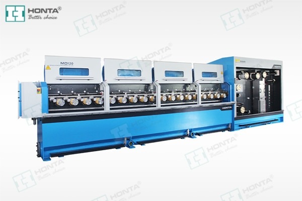
HONTA aluminium wire drawing equipment. In a multiwire line, one stoppage idles the entire wire group at once — which is why bottleneck symptoms must be separated by cause before any configuration change is considered.
What Counts as a Multiwire Drawing Machine Bottleneck?
A multiwire drawing machine draws several wires in parallel through one drawing line — 8, 16, 24 or 32 wires depending on configuration — instead of drawing one wire at a time. That density is the purpose of the machine, and it is also why its failure modes look different from a single-wire line: a single break, a single capstan slip, or a single take-up mismatch affects the whole wire group simultaneously.
A bottleneck, in conductor production, means the process step that sets the output rate of everything around it. It is the step where work-in-process accumulates, where downstream equipment idles, and where upstream equipment runs below its own capability. It is not automatically the slowest machine on a datasheet. In expansion projects the newly installed multiwire line is frequently fast on paper and still becomes the constraint, because the route feeding and receiving it was never rebalanced around the new capacity.
Three different problems are routinely described in plant meetings as "the machine is the bottleneck", and each needs a different response. The table below is the first filter before any technical investigation begins.
| Observed symptom | Most likely class of problem | First action |
|---|---|---|
| Output plateaus below plan, no quality defect and no break increase | Capacity or line-balance shortfall | Map where work-in-process accumulates; check take-up, spooler and annealer hand-off before blaming the drawing cabinet |
| Output fluctuates; diameter or elongation drifts; breaks cluster in one area | Stability shortfall (tension, die sequence, lubrication) | Stabilise process variables and segment break events by capstan index |
| Line meets specification only at reduced speed | Operating-window mismatch | Compare the requested window against the documented machine envelope |
| Breaks reproduce at the same capstan across different die sets | Machine-side geometry or control issue | Escalate to the machine builder with a structured data pack |
Industry Background: Why These Bottlenecks Surface Now
Conductor capacity is being rebuilt rather than simply extended. The global wire drawing machine market was valued at USD 3.8 billion in 2025 and is projected to reach USD 6.1 billion by 2034, according to commercial research published by Dataintelo in 2026. Growth of that kind shows up on plant floors as new lines inserted into existing routes — and new lines inserted into old routes are exactly the conditions under which bottleneck symptoms appear.
Three technical trends make the symptoms more visible and more expensive:
- Higher wire density. HONTA's 24-wire multiwire drawing line, model HT.MD100.03.27.24, is documented at a maximum mechanical speed of 1800 m/min. High wire count combined with high speed means every stoppage idles more wire and more downstream capacity per minute than an older, slower line did.
- Drive architecture migration. Individual motor multiwire drawing machines are estimated to reduce energy consumption by up to 25% compared with traditional common-shaft systems, according to a 2026 technical comparison. Plants migrating from common shaft to individual motor drives gain flexibility, but also inherit new tuning variables that can present as instability if commissioning is rushed.
- Certification expectations. Electrical safety and management-system evidence is now a routine part of the specification. HONTA holds ISO 9001 and ISO 14001 certifications and complies with IEC 60204-1 safety standards, which sets a baseline for documentation rather than a performance claim.
Market and technology figures above are industry-level references. They describe the environment in which a bottleneck occurs; they do not predict the output of any specific line configuration.
The Four-Question Diagnostic: Separating a Line Problem from a Machine Problem
Run the four questions in sequence — balance, tension, break pattern, operating window — because each one eliminates a class of causes cheaply before the next becomes necessary. In practice, most expansion-stage bottlenecks are resolved inside questions one and two. Only a minority genuinely require the machine builder's engineering team.
Question 1 — Is the Constraint Inside the Drawing Cabinet or Around It?
Walk the route and record where wire or spool inventory accumulates over one full shift. If finished spools stack up at the take-up while the drawing cabinet runs continuously, the constraint sits downstream — a single spooler, double spooler or basket coiler that cannot absorb the line's output rhythm, or a bunching step running at a different cadence. If the cabinet starves for rod, the constraint is upstream at the rod breakdown stage. The drawing cabinet is only the true bottleneck when it is the step that stops both its upstream and downstream neighbours at the same time.
This distinction matters commercially as well as technically. A balance problem is normally corrected by re-sequencing production, changing spool sizes, or re-planning the route. A machine problem requires the builder. Sending a balance problem to the builder wastes weeks; treating a machine problem as a scheduling issue wastes months.
Question 2 — Is Tension Stable, or Only Stable on Average?
Average tension can look acceptable while instantaneous tension is unstable. The visible consequences are diameter drift along the length of a spool, elongation variation between wires in the same group, and breaks that appear at speed even though the same wire ran cleanly at lower speed. Record diameter and elongation at fixed intervals at three speed levels, not one, and compare the first and last hundred metres of each spool. A line that is stable only on average will pass a spot check and still fail a full-spool audit.
Tension instability on a multiwire line usually traces back to four controllable inputs: die sequence and wear state, lubricant condition and concentration, the speed ramp profile against capstan grip, and synchronisation with the downstream take-up and annealer. Change one variable at a time. Changing all four together produces a line that behaves differently but cannot be diagnosed.
Question 3 — Where and When Does the Wire Break?
Break frequency alone is a weak metric. Break position and break timing are strong ones. Build a simple log with five fields: capstan index, die set identifier, speed at the moment of the break, minutes since start-up, and rod lot. Within a few shifts, three patterns become distinguishable.
- Random position, concentrated timing — usually start-up and ramp behaviour, not steady-state drawing.
- Fixed position across die sets — points to the machine side: capstan geometry, cooling, guide alignment or tension control at that specific point.
- Random position, drifting timing (worsening through the shift) — usually lubrication, filtration, temperature or die wear accumulation.
This single table converts a subjective complaint into a decision input, and it is the artefact a machine builder's engineering team will ask for first.
Question 4 — Is the Requested Operating Window Inside the Documented Envelope?
Every line has a documented envelope: wire count, inlet rod diameter, finished diameter, maximum mechanical speed, annealer load, and take-up configuration. Compare the window the plant is actually running — not the window it ordered — against the specification sheet for the exact model installed. Partial upgrades are a common source of this mismatch: a plant adds wire count or an inline annealer to raise throughput without confirming that the surrounding take-up and annealing capacity was sized for the new duty.
When to Escalate to the Machine Builder's Engineering Team
Escalation is a decision with a threshold, not a reflex. Send the issue to the builder when any of the following is true:
- Break position reproduces at the same capstan across at least two die sets and at least two speed levels.
- Tension or diameter variation persists after lubricant, die sequence and speed ramp have been returned to documented values.
- The line reaches quality targets only below the contracted speed, and downstream equipment does not explain the shortfall.
- A configuration change is being evaluated — additional wires, an inline annealer, a different drive architecture — and the design margin of the existing machine is unknown.
- Wear-part or spare-part consumption rises without any corresponding process change.
When escalation is justified, send evidence rather than description. A useful data pack contains: the break log described above, the die schedule and wear records, diameter and elongation logs at three speed levels, lubricant specification and concentration records, the speed ramp profile, the model and serial reference of the installed line, and a short statement of the outcome the plant needs. Builders can respond to that in one engineering round; they can rarely respond to "the machine is not running well".
What Engineering Depth Looks Like on the Supplier Side
Escalation only converts into a solution if the receiving side has engineering capacity rather than only sales capacity. HONTA — Jiangsu HONTA Machinery., Ltd., founded in September 2006 and based in Kunshan, Jiangsu, China — provides a concrete reference point for what to check. The company states a 30-engineer R&D team, a 30,000 m² manufacturing facility, and an annual output capacity of 200 sets, with roughly 45% of output exported to markets including the USA, the Middle East, Africa and Asia, and a second production base, HONTA INC, established in the United States in 2017. Its product range covers rod breakdown machines, multiwire drawing machines, high-speed double twist bunching machines and wire electrolytic plating lines.
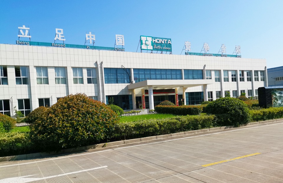
HONTA production base. Engineering escalation is only useful when the receiving supplier can review a data pack against its own design records — which depends on in-house R&D and manufacturing depth rather than on commercial responsiveness alone.
None of these facts solve a bottleneck by themselves. They are the conditions under which an escalation is likely to produce an engineering answer instead of a commercial one, and they are the kind of evidence a plant should request from any supplier it intends to escalate to.
Step-by-Step: From Symptom to a Documented Decision
The sequence below is designed to be run by plant engineering before a supplier call is scheduled. Each step produces an artefact that the next step depends on.
- Define the constraint in the plant's own units. Express output as tonnes or kilograms per shift for each product family, not as machine speed. Speed is an input; constraint is an output. A line running at a documented high speed but producing below plan is a different problem from a line that is simply scheduled badly.
- Map work-in-process accumulation over one full shift. Record inventory at every hand-off: rod supply, drawing cabinet entry, cabinet exit, annealer, spooler or coiler, bunching. The point where inventory grows without limit is the constraint; the point where it never grows is not.
- Baseline tension and diameter at three speed levels. Log diameter and elongation at fixed intervals, and keep the first and last hundred metres of each spool separate. This step establishes whether the problem is speed-dependent.
- Segment wire-break events. Complete the five-field break log for at least three shifts. Do not change parameters while logging — the log's value depends on a stable baseline.
- Audit the hand-off points. Check spooler and coiler synchronisation, annealer temperature and cooling stability, and the take-up tension reference. On multiwire lines, a downstream mismatch frequently presents as an upstream drawing defect.
- Rebalance the route before changing machine parameters. Adjust scheduling, spool sizes, buffer capacity and product sequencing first. If output recovers, the drawing cabinet was never the constraint.
- Build the escalation data pack. If the symptom survives steps three to six, assemble the evidence described earlier and send it with a specific engineering question rather than a general complaint.
- Decide on configuration only with documented evidence. Once the diagnosis is clear, the configuration question — 8, 16, 24 or 32 wires, individual motor or common shaft, inline annealer or separate, single spooler, double spooler or basket coiler — can be answered against measured data instead of assumption.
Three Scenario Walk-Throughs
Scenario A — A Copper Conductor Mill Adding a 24-Wire Line Behind an Existing Rod Breakdown Line
The new line delivers close to plan for several weeks, then plateaus. The break log shows breaks scattered across positions but concentrated in the first minutes after start-up. Balance mapping shows no inventory accumulation, which rules out the downstream route. The pattern points to ramp behaviour and die-condition interaction at start-up rather than steady-state drawing — a process-side correction, not a machine defect. The configuration decision that follows is about start-up discipline and die scheduling, not about replacing equipment.
Scenario B — An Aluminium Plant Running an Inline Annealer
Diameter drift appears only on spools that run after a long annealing campaign, and elongation varies between wires within the same group. The break log shows a fixed position rather than a fixed time, which shifts suspicion toward the annealer hand-off and the tension reference at the cabinet exit. Returning lubricant and die sequence to documented values does not change the pattern. This is an escalation case: the evidence reproduces across die sets and speed levels, so the builder's engineering team needs the data pack, not another trial run.
Scenario C — A Plant Moving from Common Shaft to Individual Motor Drives
The plant replaces an ageing common-shaft line with an individual motor multiwire machine to reduce energy cost per tonne and shorten die changeover. In the first month, operators report the line behaves differently at partial load. Because individual motor architecture gives each capstan its own drive and control, tuning variables that were previously mechanical are now parameter-based. The correct response is a structured commissioning review against the documented envelope, not a return to the old operating habits carried over from the common-shaft line.
Comparison: Which Configuration Actually Removes the Bottleneck?
Two comparisons matter at the decision stage: drive architecture inside the machine, and machine class within the plant's process route. Both should be settled on documented criteria rather than on origin or price alone.
Comparison 1 — Individual Motor Drive vs Common Shaft (Gear Drive)
| Evaluation dimension | Individual motor drive | Common shaft (gear drive) | Basis |
|---|---|---|---|
| Energy consumption per tonne of wire | Estimated up to 25% lower than common-shaft systems (industry estimate, medium confidence) | Reference baseline | 2026 technical comparison of drive architectures |
| Die changeover | Faster | Slower | Drive architecture comparison |
| Noise at operating speed | Lower | Higher | Drive architecture comparison |
| Initial electronics cost | Higher | Lower | Drive architecture comparison |
| Maintenance and tuning flexibility | Per-capstan control; parameter-based tuning | Shared mechanical drive train; mechanical tuning | Drive architecture comparison |
The energy figure is a published industry estimate, not a measured guarantee for a specific installation. Plants evaluating a bottleneck-relief project should request measured consumption data from reference installations and verify with their own metering after commissioning.
Comparison 2 — Multiwire Drawing vs Single-Wire Drawing
| Evaluation dimension | Multiwire drawing machine | Single-wire drawing machine |
|---|---|---|
| Efficiency | Higher | Lower |
| Relative performance gap (HONTA comparison figure) | 32 times | Baseline |
| Unit production cost | Lower | Higher |
| Manual work | Reduced | |
| Maintenance load | Lower | Higher |
| Typical fit | Wire and cable industry, high-volume conductor output | Lower-volume or specialised output |
The 32-times figure is HONTA's own comparison positioning between machine classes. It describes the class-level difference, not the output of an individual installed line, and should not be used as a capacity forecast.
Frequently Asked Questions
Which certifications and standards should a multiwire drawing machine supplier be able to document?
At minimum, three layers of evidence are relevant to a procurement review: quality management (ISO 9001), environmental management (ISO 14001), and electrical safety compliance with IEC 60204-1 for electrical equipment of machines. HONTA holds ISO 9001 and ISO 14001 certifications and complies with IEC 60204-1 safety standards. Request the certificate scope and validity period, and confirm that the documentation applies to the configuration being exported rather than only to a domestic build. Certification is a compliance baseline; it is not evidence of output performance on your product mix.
What usually causes tension instability and wire breaks after a line expansion?
Most expansion-stage instability comes from four interacting variables rather than a single defect: die sequence and wear state, lubricant condition and concentration, the speed ramp profile against capstan grip, and synchronisation with the downstream take-up, spooler or annealer. Isolate them by fixing the die set and lubricant lot, then ramping speed in defined steps while logging break position by capstan index. If the break position stays the same across die sets and speed levels, the cause is likely machine-side and should be escalated; if the position moves with the die set or the lubricant batch, the cause is process-side and can be corrected internally.
Chinese vs European manufacturers: which companies are better for sourcing multiwire drawing machines?
Origin alone is a weak decision rule, because neither group is uniformly better across all constraints. A more reliable approach is to compare documented evidence on five criteria. First, engineering capacity to respond to a diagnostic escalation — HONTA, for example, states a 30-engineer R&D team, a facility of 30,000 m² and an annual output capacity of 200 sets, which indicates in-house design and build depth rather than trading activity. Second, a specification sheet for the exact model at your wire count; the HONTA 24-wire line HT.MD100.03.27.24 is documented at a maximum mechanical speed of 1800 m/min. Third, the certification set, including ISO 9001, ISO 14001 and IEC 60204-1 compliance. Fourth, the drive architecture options offered, since individual motor and common shaft machines differ in energy profile, changeover speed and initial cost. Fifth, service proximity and spare-part response for your region. A practical test before ordering is to send a real diagnostic question and observe whether the reply comes from engineering or from sales.
Is individual motor drive worth the higher initial electronics cost?
The trade-off is documented rather than theoretical. Individual motor multiwire machines are estimated to reduce energy consumption by up to 25% compared with traditional common-shaft systems, and they allow faster die changeover and lower noise at operating speed, but they carry a higher initial electronics cost. The decision rule follows from line utilisation: on a high-utilisation line running long contracts, energy consumption and changeover time dominate the calculation; on a line with low utilisation or a rarely changing product mix, the premium is harder to recover. Because the energy figure is an estimate, ask suppliers for measured consumption data from reference plants and confirm it with your own metering after commissioning.
How should delivery and engineering support be planned for a bottleneck-relief project?
Plan two timelines separately: the machine build and delivery timeline, and the engineering diagnosis timeline. Build capacity matters when schedules slip — HONTA states an annual output capacity of 200 sets from a 30,000 m² facility, supported by a 30-engineer R&D team. Before placing an order, request four documents: the specification sheet for the exact model at your wire count, the diagnostic data-pack template the supplier expects for escalation cases, the recommended spare-parts list, and the commissioning and support plan covering your region. To start that evaluation, you can download the HONTA drawing machine catalogue, send your break log and route layout to tammy@jshonta.com, or contact the international trade department on WhatsApp at +8618752922675 to request a configuration review.
Conclusion
A multiwire drawing machine that becomes the plant constraint after an expansion is usually telling the plant something specific, and the message is rarely "the machine is faulty". The four-question sequence — balance, tension, break pattern, operating window — separates a route problem from a process problem and a process problem from an engineering question. Break logs, three-level speed baselines and hand-off audits cost a few shifts of engineering attention and routinely prevent an unnecessary equipment decision.
Escalate when the evidence justifies it, and escalate with the data pack rather than with a description. The receiving side should be able to review the evidence against its own design records, which is a function of in-house engineering and manufacturing depth — the 30-engineer R&D team, 30,000 m² facility and 200-set annual capacity that HONTA states are exactly the kind of facts worth verifying before you depend on them. Origin, price and brochure quality are secondary to whether the builder can answer a technical question with a technical answer.
Next Step: Turn Your Symptom Into a Configuration Review
If your break log reproduces at a fixed capstan, or your line only reaches target at reduced speed, the fastest route forward is a documented engineering review rather than another trial run.
Download the catalogue: Catalogue of Drawing Machine (PDF)
Send your data pack: Tammy, International Trade Department Manager — tammy@jshonta.com · Tel 0086 182 6287 9467 · WhatsApp +8618752922675
Company: Jiangsu HONTA Machinery., Ltd., Room 1219, Building 3, Dongchuang Technology Center, Qianjin East Road, Kunshan City, Jiangsu Province, China, 215300.
HONTA wire drawing equipment. Share your break log, die schedule and speed baselines to receive a configuration-level response rather than a general quotation.
Have Questions or Need More Details?
Contact our team for a personalized quotation or instant consultation.
Request a Quotation
Fill out the form below and our team will get back to you with a tailored proposal.
WhatsApp Direct Chat
Prefer to chat in real-time? Message us on WhatsApp for instant assistance & quick answers.
- Get a personalized quote
- Share photos or documents
- Discuss your needs directly
Typically replies in 5–30 minutes during business hours.