
Multiwire Drawing Machine: Rod Breakdown to Bunching Guide
Short answer: a multiwire drawing machine is specified from the line around it, not from a catalogue page. Conductor material, the inlet-to-outlet diameter window, the output you need at final diameter, the floor space you actually have, and the equipment immediately upstream and downstream decide most of the configuration before any model number is discussed. A project written down in those five terms produces quotes you can compare; a project described only as a need for a drawing line does not.
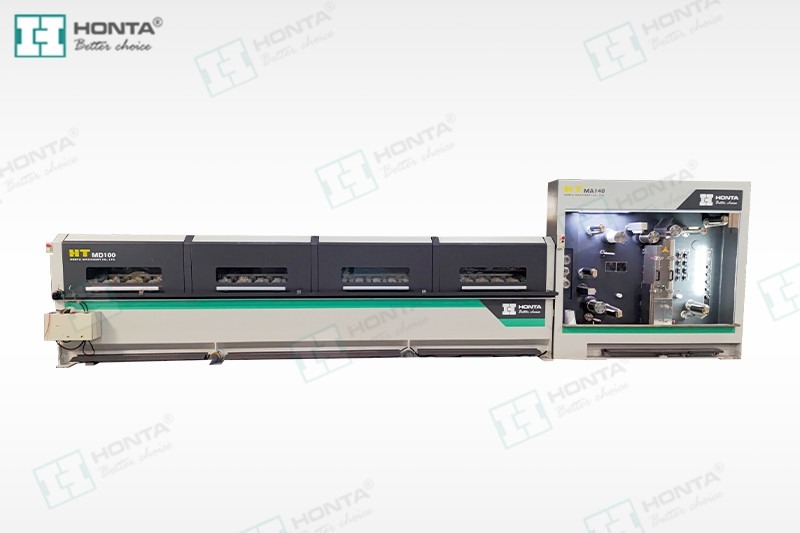
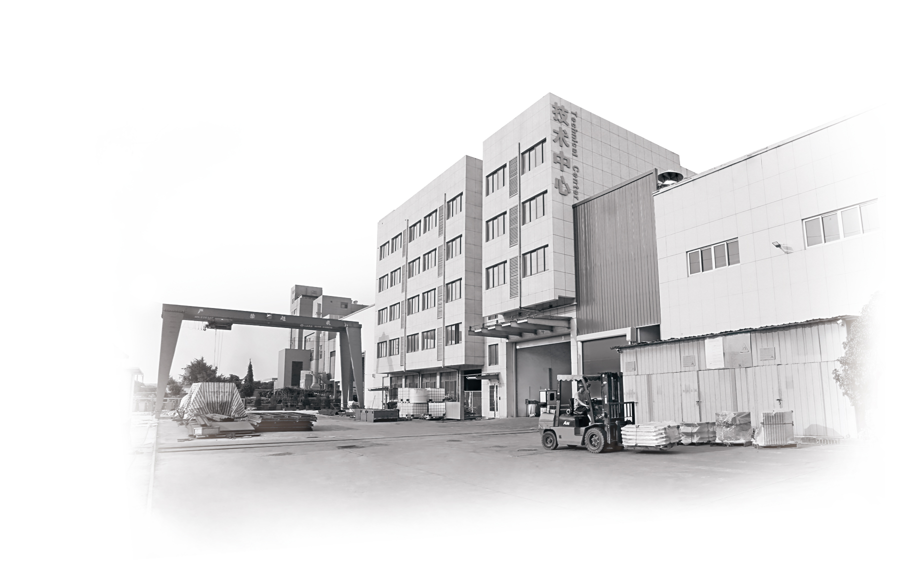
This application guide is written for cable and conductor plants at the research and evaluation stage. It works through five production scenarios — copper rod breakdown feeding a 16-wire drawing line, aluminium feed, high-density 24-wire output with individual motor drives, take-up and spooling matched to a bunching stage, and brownfield retrofits — and shows for each one which input changes which decision. HONTA (Jiangsu HONTA Machinery., Ltd.) is a conductor drawing and stranding equipment manufacturer founded in September 2006, with a 30,000 m² manufacturing facility, 157 employees, 30 R&D engineers and an annual output of 200 sets. Its main products are copper and aluminium rod breakdown lines, multiwire drawing line series, high-speed double twist bunching machines and wire electrolytic plating lines.
The Line, Not the Machine, Is What You Configure
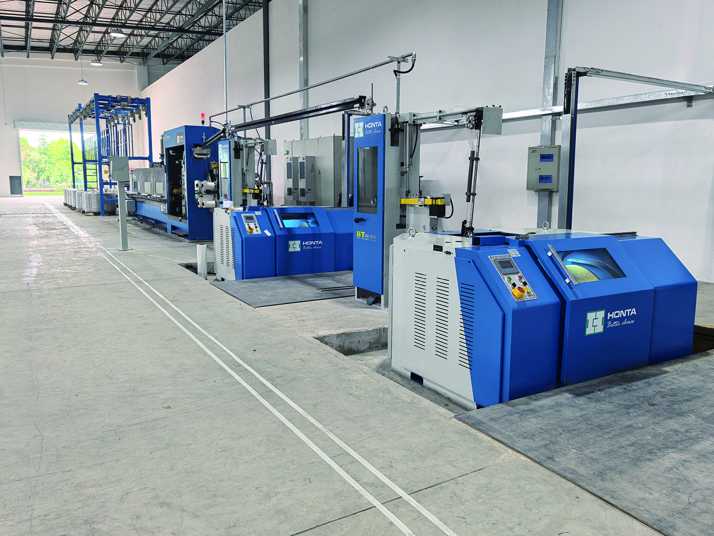
A conductor line does three separate jobs. Rod breakdown takes wire rod down to an intermediate diameter. Multiwire drawing takes that intermediate wire to final diameter across a fixed number of wires per pass. Bunching or stranding then combines the drawn wires into the conductor that leaves the plant. HONTA supplies across all three stages, which matters at specification stage: pay-off height, tension, spool format and the control handshake between stages can be settled with one engineering conversation instead of being negotiated between three vendors after the order.
HONTA's application record for the wire and cable industry describes the operating condition these machines are built for: continuous industrial production, high-speed automated operation requiring stable tension control and accurate wire alignment, run under PLC control with computer-screen parameter settings and automatic tension modes. That description doubles as a screening checklist. Any project that cannot meet those conditions — intermittent batches, unstable pay-off, manual tension adjustment — should be flagged before quoting rather than discovered at commissioning.
Five Scenario Inputs That Decide Most of the Configuration
Before a supplier can answer with a model, five inputs need to be on paper. Each one closes a set of options and opens another, and each one is verifiable in the final technical agreement.
| Scenario input | What it decides | What the enquiry should state |
|---|---|---|
| Conductor material | Which drawing line family and process set-up is quoted | Copper or aluminium, temper/condition, and whether both must run on one line |
| Inlet and outlet diameter | Wire count, reduction sequence, die and capstan set-up | Inlet (rod or intermediate) diameter, final diameter, tolerance |
| Target output | Speed and wire-count combination, take-up rate | Required output at a stated final diameter, with shift pattern |
| Floor space | Line length, layout, take-up arrangement, crane and maintenance access | Available length and width, ceiling height, access routes |
| Downstream equipment | Take-up and spool format, tension interface, controls | Bunching or stranding machine model, spool type and size, existing pay-off |
Scenario 1: Copper Rod Breakdown Feeding a 16-Wire Drawing Line
This is the most common mid-volume project shape. HONTA's 16-wire machine, model HT.MD100B.16.22D.01, is published with an inlet wire range of 1.8–2.0 mm and an outlet range of 0.18–0.5 mm, driven by a Siemens motor and controlled by a Siemens PLC. Those two diameter figures do most of the early work in a scenario plan: they tell you what the rod breakdown stage must deliver as intermediate wire, and they tell you the finest gauge the drawing stage can hand to the bunching stage without a second drawing step.
The next question is annealing. HONTA's matched-equipment list for wire drawing applications includes annealing furnaces, annealers, pay-off and take-up units, winding and unwinding machines, and single or double-disc take-up machines. Annealing therefore sits inside the line scope rather than outside it, and the technical agreement should say whether it is included, at which stage, and for which conductor range. Leaving it as an assumption is one of the most common causes of a quote that looks cheaper than the line it eventually requires.
A third question is where the order book concentrates inside the published outlet range. A plant running mostly fine conductor near the 0.18–0.25 mm end faces different die-change frequency and break-recovery pressure than one running nearer 0.4–0.5 mm. That difference is what makes drive architecture worth discussing at evaluation stage rather than after installation.

Scenario 2: Aluminium Feed and the Questions It Changes
An aluminium conductor project keeps the same five inputs and changes their values. HONTA's product range covers aluminium rod breakdown lines alongside copper, so the line architecture is familiar; the differences appear in the process set-up, the annealing decision and the tension and alignment tolerance the line must hold at the required speed, because aluminium behaves differently from copper in the drawing pass.
Three items should be pinned down in writing. First, the intermediate diameter the aluminium rod breakdown line must deliver to the drawing stage. Second, whether the drawing stage must anneal and to what specification — annealers and annealing furnaces appear in HONTA's matched-equipment list as separate items precisely because that scope varies by project. Third, whether one machine is expected to serve both copper and aluminium. That is an engineering answer, not a catalogue answer: each model is configured to a stated inlet and outlet window, as the 16-wire example shows with its published 1.8–2.0 mm inlet and 0.18–0.5 mm outlet range. Ask for the dual-material answer against your own diameter list, and check it against the published range of the specific model rather than against the product family.
Scenario 3: High-Density Output, 24-Wire Lines and Individual Motor Drives
When volume justifies density, wire count rises. HONTA's published specification for the 24-wire multiwire drawing line HT.MD100.03.27.24 lists a maximum mechanical speed of 1,800 m/min. Two cautions apply when that number enters a business case. It is a mechanical maximum from product documentation, not a guaranteed output at your final diameter. And hourly output depends on wire count, diameter, reduction sequence and uptime, so the useful question to a supplier is output at a stated diameter under stated conditions.
The second high-density decision is drive architecture. An HTNXT technical comparison of individual-motor and common-shaft machines notes that individual motor drives allow faster die changeover and lower noise but carry higher initial electronics cost. The same comparison estimates that individual motor machines can reduce energy consumption by up to 25% against common-shaft systems; that figure is a derived industry estimate rather than a measured test result, so it should be treated as a direction to verify against your own load profile and running hours.
| Dimension | Individual motor drive | Common shaft (gear drive) |
|---|---|---|
| Energy consumption | Estimated up to 25% lower in an industry comparison — derived figure, verify locally | Baseline in that same comparison |
| Die changeover | Faster changeover reported | Slower changeover reported |
| Noise | Lower noise reported | Higher noise reported |
| Initial cost | Higher electronics cost | Lower initial electronics cost |
How a plant should read that table depends on its own pattern. With high running hours and frequent size changes, the operational arguments for individual motors strengthen. With low utilisation and a narrow, stable product range, the electronics premium is harder to recover and the decision deserves a payback calculation rather than a preference.
Scenario 4: Matching Take-Up and Spooling to the Bunching Stage
The drawing machine ends at the take-up, and the take-up is decided by the next machine, not by the drawing cabinet. Take-up formats differ across the industry — single spooler, double spooler or basket coiler — and the format, spool size and tension range must match the pay-off of the bunching or stranding machine that receives the wire. HONTA's matched-equipment list names single and double-disc take-up machines, winding and unwinding machines, and pay-off and take-up units inside the drawing application scope, with automatic tension modes as part of normal operation.
The practical sequence is short. Name the downstream bunching or stranding machine and its pay-off requirement. Specify spool type, size and tension range against it. Agree the control handshake between drawing and bunching so that a stop on one machine does not become a wire break on the other. If drawn wire is also sold as single wire rather than bunched in-house, spool format and winding quality become a delivery requirement rather than an internal one, and should be tested together with the drawing parameters rather than separately.
Scenario 5: Brownfield Retrofits and Tight Floor Space
In a brownfield project the free variables shrink before the technical discussion starts. Existing pay-off equipment, building columns, crane coverage and the fixed position of the bunching line often determine the layout before the machine choice does. Two levers are worth raising early. The first is customization scope: HONTA offers ODM production with customization of colour and model type of components and parts, and in a retrofit the useful application is matching a new line to an existing hall and existing interfaces rather than rebuilding the building.
The second lever is staged replacement. Minimum order quantity is one set, so replacing one stage of a line — for example the drawing stage while the existing rod breakdown and bunching equipment stay in place — is a project shape the supplier can quote. With lead time stated at 90 days and monthly capacity at 15 sets, the schedule question becomes whether the new stage lands inside the planned shutdown window. The layout drawing, including maintenance access and wire routing, should be approved against the real hall before the order, not after delivery.
Turning Scenario Inputs Into a Written Specification
The seven steps below convert a scenario into something a supplier can answer and you can verify. They apply to copper and aluminium projects alike.
- Fix the diameter window first. Inlet range, final diameter and tolerance. Every other parameter is secondary to this one, because it fixes the die sequence and the wire path.
- Turn output into a testable number. State the required output at a stated final diameter and shift pattern, and ask the supplier to state the speed and efficiency assumption behind the figure.
- Map the existing line. Pay-off, annealer, take-up and downstream bunching or stranding, with models and spool data where they exist.
- Draw the floor plan. Line length, width, ceiling clearance, crane coverage, maintenance access and wire routing between stages.
- Choose the drive architecture deliberately. Individual motor drives or common shaft, decided against running hours, size-change frequency and a payback calculation.
- Fix spool and take-up. Format, size, tension range and the control interface to the next machine.
- Agree verification before the order. 100% testing, acceptance parameters, documentation set, and after-sales mode — remote support, on-site support, or both.
Where HONTA's Engineering Team Changes the Answer
Three of HONTA's company facts are directly relevant to a scenario project rather than being background. The first is engineering capacity: 30 R&D engineers against an annual output of 200 sets and a monthly capacity of 15 sets, working from a 30,000 m² facility with 157 employees. For a buyer, that combination matters when the layout is non-standard — a retrofit with a constrained hall, a mixed copper and aluminium programme, or a take-up arrangement that has to match an existing bunching line.
The second is export experience. HONTA reports a 45% export ratio and main markets in the USA, the Middle East, Africa and Asia, and has operated a second production base in the United States, HONTA INC, since 2017. In practice that means documentation, power configuration and packing questions for an export project are routine rather than bespoke, and North American projects have a nearer support point. The third is after-sales: support is offered by remote and on-site channels, which is the practical difference between a line that returns to production quickly after a fault and one that waits for a visit.
Documented application evidence is thinner than marketing language usually suggests, so it is worth stating precisely. HONTA's case record includes a wire and cable factory running two sets for three years, reported to steadily produce products that meet the customer's requirements, with speed and efficiency cited as the highlights. That is a documented customer report, not an independently audited performance study, and it should be read as evidence of continuity rather than as a guarantee of output at your diameters.

What This Guide Cannot Confirm
- Output at your diameter. Published maximum speeds are mechanical limits. Hourly output for your conductor, wire count and reduction sequence has to come from a technical agreement, not from a table.
- Energy and noise figures. The up-to-25% energy reduction for individual motor drives is a derived industry estimate. Machine-specific consumption and noise data are not part of the published documentation reviewed here.
- Footprint. Line length and take-up arrangement must come from an approved layout drawing for your building, including access and crane coverage.
- Market approvals. Third-party reporting lists HONTA as holding ISO 9001 and ISO 14001 certification and complying with IEC 60204-1 safety requirements. Destination-specific approvals depend on the market and the project, and belong in the technical agreement.
- Market forecasts. Commercial research cited for the category — for example a global wire drawing machine market valued at USD 3.8 billion in 2025 with a projection to USD 6.1 billion by 2034 — is context for planning, not evidence of demand for a specific configuration.
Scenario Planning FAQ
Which standards should a multiwire drawing line scenario reference?
Third-party reporting lists HONTA as holding ISO 9001 and ISO 14001 certification and complying with IEC 60204-1 safety requirements, and HONTA states 100% testing of equipment. Those are the verifiable reference points available at evaluation stage. Destination-specific approvals vary by market and must be confirmed project by project inside the technical agreement rather than assumed from the machine category.
Can one multiwire drawing machine cover both copper and aluminium scenarios?
HONTA's range includes both copper and aluminium rod breakdown lines, but each drawing machine is configured to a stated diameter window — the 16-wire HT.MD100B.16.22D.01, for example, is published at 1.8–2.0 mm inlet and 0.18–0.5 mm outlet. Whether a single unit can serve both materials depends on your diameter list, the annealing scope and the tension set-up, so the answer should be requested in writing against those inputs and checked against the published range of the specific model.
What drives the capital cost of a multiwire drawing line?
Cost is driven by configuration rather than by a single headline specification: wire count, drive architecture (individual motor drives carry higher initial electronics cost than a common shaft), whether annealing equipment is inside the scope, take-up and spool format, automation level, and the customization agreed under ODM — colour and model type of components and parts. How much of the existing line is reused in a retrofit also changes the scope substantially.
How can a plant validate a configuration before committing?
Validation runs through documents and tests rather than a trial machine. Agree a written specification with diameters, output at a stated diameter and acceptance parameters; approve the layout drawing against the real hall; and use the 100% test before shipment as the formal check point. Because minimum order quantity is one set, a single-stage replacement can also be validated in production before a second stage is ordered.
What lead time should a scenario plan assume?
HONTA states a 90-day lead time, a monthly capacity of 15 sets and an annual output of 200 sets. Customization under ODM, an unusual take-up arrangement or a layout that has to match existing equipment can extend the schedule, so the contractual date should be tied to the final approved specification rather than to the initial enquiry.
How do we start a scenario review with HONTA?
Send the five inputs in one message: conductor material, inlet and outlet diameter window, required output at final diameter, available floor space with access constraints, and the downstream bunching or stranding equipment including spool data. HONTA's 30-engineer R&D team can then respond with a configuration and layout proposal. The drawing machine catalogue covers the product range, and further detail is available through jshonta.com.
Conclusion
Multiwire drawing machine projects fail at the specification stage far more often than at the machine stage. The five inputs — material, diameter window, output at final diameter, floor space and downstream equipment — decide whether the drawing line, the rod breakdown line, the annealer and the take-up form a working line or four correctly built machines that do not quite fit together. Write them down, put a number and a condition against each, and require the supplier to answer in the same terms.
HONTA's role in that process is configuration and engineering support across rod breakdown, multiwire drawing and high-speed double twist bunching, backed by a documented range, ODM customization and both remote and on-site after-sales support. The next practical step is a written scenario review, not a model number.
Have Questions or Need More Details?
Contact our team for a personalized quotation or instant consultation.
Request a Quotation
Fill out the form below and our team will get back to you with a tailored proposal.
WhatsApp Direct Chat
Prefer to chat in real-time? Message us on WhatsApp for instant assistance & quick answers.
- Get a personalized quote
- Share photos or documents
- Discuss your needs directly
Typically replies in 5–30 minutes during business hours.