
Multiwire Drawing Machine Take-Up and Spooling: A Technical Guide
The take-up end of a multiwire drawing machine decides whether the tolerances held in the drawing cabinet survive to the shipping floor. Four jobs have to be engineered at the same time: tension held consistently across every wire in the set, each wire guided onto its spool without crossovers or edge build, spool changes that fit inside the production rhythm, and a finished package the downstream bunching machine can accept without rework. This guide covers those four jobs, the parameters a buyer should specify for each, and the shop-floor checks that reveal whether a take-up was engineered or improvised.
What the take-up end is actually responsible for
The take-up and spooling section converts a continuous, multi-strand drawing process into discrete packages. It is not a storage area at the end of the line. It is a tension-controlled, multi-spindle winding system, and its behaviour determines whether the wire diameter and surface condition produced in the drawing cabinet are still present on the spool that reaches the bunching machine.
Specification effort is usually distributed unevenly. Dies, capstan geometry, reduction schedule and annealer capacity receive detailed attention because they define the metallurgical result. The take-up is often compressed into a single line in the inquiry — “spooler, one set” — while the drawing section is described in full. When that happens, capital is committed to drawing capability whose output cannot be repeated package after package.
Three failure modes account for most of the distance between a specified take-up and a working one. Tension divergence: the wires in the set do not arrive at the spool under the same tension, so residual elongation differs from spindle to spindle. Package defects: crossovers, edge build and embedded turns make the spool difficult to pay off. Interface failure: the spool the drawing line produces is not the package the downstream bunching machine can accept at its own pace.

Why take-up moved from accessory to constraint
Multiwire drawing expanded by multiplying one operation across a growing number of wires. Configurations are described by wire count — 8, 16, 24 and 32 wires are the labels used in the market — and every additional wire multiplies the workload at the take-up rather than at the die box. A 24-wire machine carries 24 tension zones, 24 traverse positions and 24 wire ends to secure at every changeover.
Speed changes the arithmetic further. HONTA’s published specification for its 24-wire multiwire drawing line HT.MD100.03.27.24 lists a maximum mechanical speed of 1,800 m/min. At that class of line speed a spool fills quickly, so changeover frequency rises and changeover stops behaving like housekeeping and starts behaving like a production-rate variable. A take-up that cannot match the changeover rhythm of the drawing section caps the whole line, whatever the dies are capable of.
The downstream side has become more tightly coupled as well. Conductor from a drawing line normally proceeds to bunching or stranding, and HONTA builds a High Speed Double Twist Bunching Machine within the same product range as its multiwire drawing machines. Once the spool is the input to a specific bunching machine, package format stops being a packaging decision and becomes an engineering interface: barrel diameter, payload, layer quality and wire-end condition all have to be acceptable on the receiving side.
Tension consistency across every wire
Winding tension is set by the difference between the pull of the drawing capstan ahead and the resistance of the reel. As a spool builds, the wound radius grows, and a reel driven at constant torque will not hold constant tension — the wire tightens as the package grows unless the control system compensates. Winding tension therefore has to be tapered with build, whether the mechanism is a dancer roller, a load cell, or a motor torque profile tied to the calculated package diameter.
Where the wires diverge
Within one machine, no two wires are identical. Each carries its own die wear history, its own capstan slip behaviour, its own contact with the annealer, and its own path through guide rollers. Where the take-up reels share one drive and one tension reference, the control system averages those differences and the spools leave with different residual elongation. The effect is easy to miss at the drawing machine and easy to find at the bunching machine, where the wires are combined.
Individual and grouped reel drives
Reel drive architecture is the first decision to settle. Individually driven spindles allow each reel to be regulated to its own tension reference and allow a single wire break to be isolated without stopping every spindle; that is a design capability, not a promise about output. Grouped or common-shaft reels are mechanically simpler but couple the wires together, so one break or one tension fault affects the whole group. The trade-off is control hardware and commissioning effort against the ability to keep 24 or 32 wires individually regulated.
What to write into the specification
A tension figure on its own is not a specification. Ask for the control method (dancer, load cell, or open-loop torque profile); the tolerance band the supplier will accept, stated as a band rather than a single value; where tension is measured — at the reel, before the traverse, or at the drawing capstan; whether the figure is a commissioning check or a continuous control setpoint; the taper applied over a full package; and the defined response to a single wire break. Require the measurement instrument and the measurement position to be named, because tension measured at two different places on the same machine will not agree.
Spool changeover time
Changeover time is a function of mechanics and choreography rather than operator speed. The mechanical side is the spindle count, the chuck or shaft design, and whether winding stops automatically at a defined package length or mass. The choreography is the sequence of doffing, wire-end securing, reloading, restaging and restarting, plus the question of whether the drawing section keeps running into an accumulator while the spools are exchanged.
An engineered changeover has a written sequence, a defined stopping point in the process, spare reels staged within reach of the operator, and a fixed number of hands. An improvised changeover depends on the most experienced operator on the shift, and it degrades whenever that person is absent.
The specification should therefore state the changeover mode, the target time for a full set at the wire count being purchased, whether the line stops or continues, how many spare spindles must be available, and how each wire end is secured and identified. The time target has to be expressed per full set: on a 24-wire machine, a per-spool figure understates the real interruption.
Wire guiding, traverse and spool build
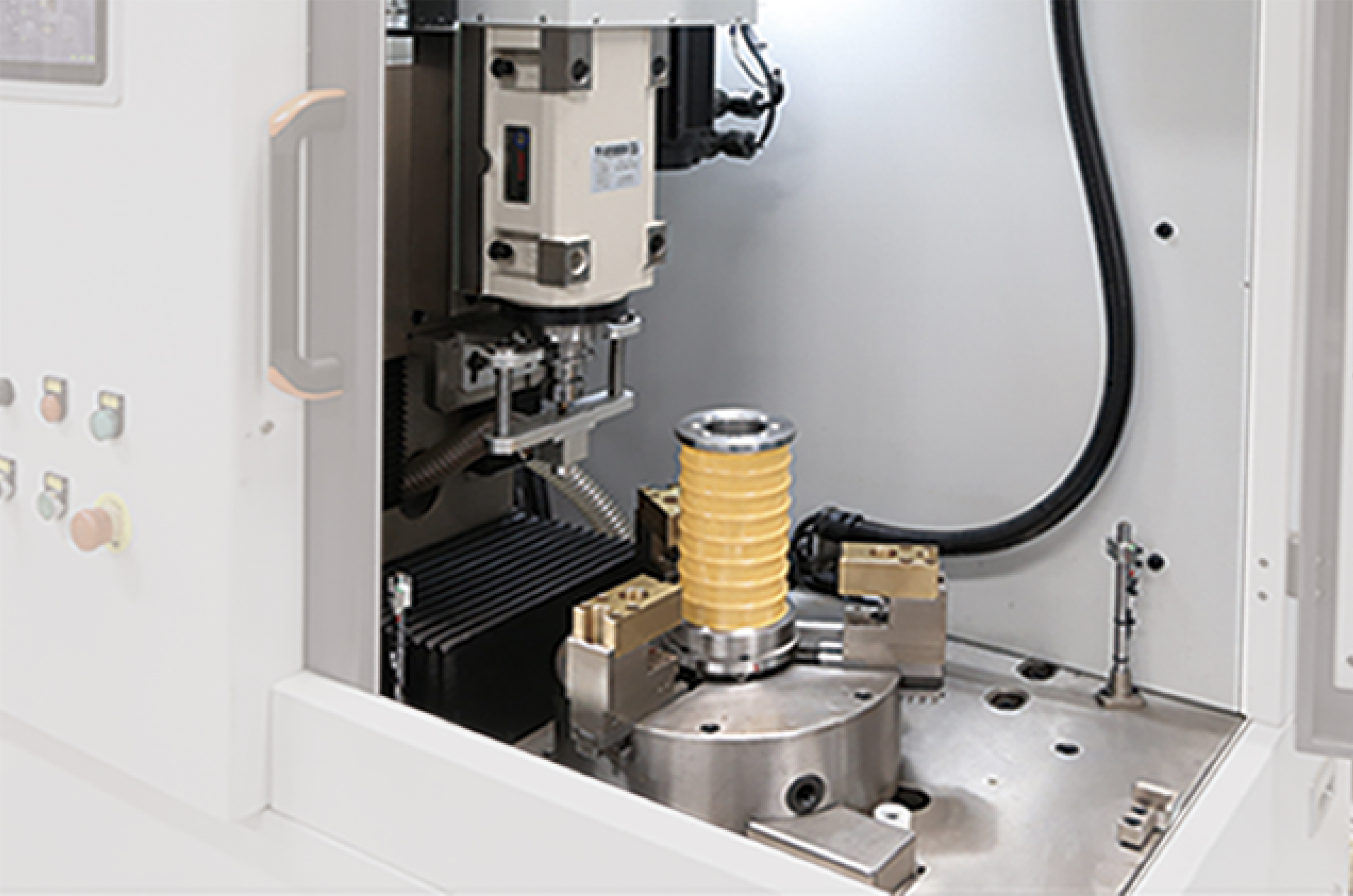
The traverse determines how each wire is laid onto its spool. Its job is to place successive turns in a controlled helix so that layers build flat and the wire can be paid off downstream without tension spikes. When the pitch is wrong for the wire diameter, or the reversal at the end of a layer is abrupt, the result is a package with crossovers, a built-up edge, or turns pressed into the layer below.
The determining elements are the traverse pitch range, the dwell at reversal, the guide material at every wire contact point, the alignment of the guides relative to the spool barrel, and the quality of the spool itself. Ceramic guides and hard-coated steel guides behave differently against soft aluminium and against fine copper; neither is universally correct, and the choice has to match both the wire and the drawing emulsion in use.
Two specification items are frequently omitted. The first is the accepted spool tolerance — barrel diameter, concentricity and surface condition — because the traverse is tuned to a spool, not to spools in general. The second is the wire contact schedule: every point the wire touches between the last capstan and the reel should be listed with its material, so that guide wear is inspected deliberately instead of being discovered later as a marking defect.
The handoff to downstream bunching
The spool leaving the drawing line is the input to whatever follows, usually bunching or stranding. That interface is more than the spool type: barrel diameter, flange size, payload mass, layer quality, wire-end fixing method and tail length, labelling and traceability, and protection against contamination during transfer and storage.
The practical test of a take-up is whether the first production spool can go directly to the downstream machine without rewinding, re-securing or rejecting the outer layers. That requires a package drawing agreed by the people who own both ends of the transfer. Where the drawing machine and the bunching machine fall inside one supplier’s scope — as they do in HONTA’s range, which covers multiwire drawing machines and the High Speed Double Twist Bunching Machine — the interface becomes one responsibility instead of a boundary between two contracts. That reduces the number of parties who can attribute a pay-off problem to the other machine; it does not by itself demonstrate performance on your wire.
For the buyer, the deliverable is a signed package specification plus a trial protocol in which the first spool from the drawing line runs on the bunching machine at the intended speed, using the wire-end handling method the operators will actually apply.
Parameters to specify before signing
The table below converts the four jobs into specification items. It deliberately avoids target values, because the correct value depends on wire diameter, wire count, line speed and the receiving machine — what matters is that each item is stated and evidenced in writing rather than left to the supplier’s default.
| Parameter | Why it decides take-up performance | Evidence to request |
|---|---|---|
| Wire count and spindle count | Every wire needs its own tension zone and traverse position | Spindle layout drawing for the quoted configuration |
| Wire diameter range per spindle | Sets traverse pitch, guide size and reel torque | Stated range per spindle, not one range for the line |
| Line speed the take-up must sustain | Changeover frequency follows line speed | Written statement that the take-up is rated to the line maximum |
| Tension control method and band | Determines variation across wires and over package build | Method, band, measurement position and instrument |
| Reel drive architecture | Individual spindles can be regulated and isolated; grouped reels couple wires | Drive schematic showing one drive per spindle or per group |
| Traverse type and pitch range | Controls layer quality, crossovers and edge build | Pitch range and reversal settings for each wire size |
| Spool standard, barrel diameter, payload | The traverse is tuned to a spool; the downstream machine accepts a package | Accepted spool tolerance and a package drawing |
| Changeover mode and target time | A rate variable on high-count machines | Written sequence and a stated time per full set |
| Wire-break response | Determines whether one break stops the whole set | Description of stop or isolate logic and restart procedure |
| Package specification for bunching | An engineering interface, not a packaging detail | Jointly signed package specification and trial protocol |
Shop-floor checks: engineered versus improvised take-up
These checks can be run during a factory acceptance test or a reference visit. None requires access to design documents; each produces evidence that either matches the quotation or does not.
- Time a full set change, not one spool. Use a stopwatch, count the people involved, and repeat three times. Ask for the committed number before the test so the comparison is against a promise rather than an impression.
- Compare tension across positions at the same moment. With a calibrated hand tensiometer, measure the outermost and innermost wire while the machine runs at production speed. A take-up with per-spindle control can be asked to explain any spread; a grouped drive will show one.
- Inspect the third layer, not the first. The first layer on an empty barrel is the easiest to lay correctly. Crossovers and edge build appear once the traverse has to follow an established surface.
- Break one wire deliberately, with the supplier’s agreement. Observe whether the machine stops as a group, isolates the affected spindle, or continues. Compare what you saw with what the specification says.
- Examine every wire contact point after a run. Guide rollers, pulleys and traverse eyes should be checked for wear marks, wire residue and surface damage, and the set of contact points should match the wire contact schedule in the documents.
- Follow one spool to the downstream machine. Time the pay-off, including finding and securing the wire end, and note whether any outer layers had to be removed before running.
- Ask for the commissioning record. It should show what was measured, with which instrument, at which position and at which speed — not merely that the machine ran.
- Check the spares list against the take-up’s wear parts. Dancer rollers, load cells, guide eyes, chuck jaws and traverse components should all be listed, together with the supplier’s support route. HONTA documents after-sales support by remote and on site.
Where HONTA fits on the take-up question
Jiangsu HONTA Machinery., Ltd. was founded in September 2006 and has worked on cable conductor drawing and stranding since then, which places the take-up question inside its core subject rather than at its edge. The company runs a 30,000 m² factory with 157 employees and an annual output of 200 sets. Around 45% of that output is exported, with the USA, the Middle East, Africa and Asia listed as main markets, and a second production base, HONTA INC, was established in the United States in 2017.
The product range covers rod breakdown machines for copper and aluminium, multiwire drawing machines, a High Speed Double Twist Bunching Machine and a wire electroplating line. Two parts of that range matter directly in take-up specification: the multiwire drawing machine, which defines the package the line produces, and the bunching machine, which defines the package it must accept.
Facts that bear on a take-up evaluation:
- A 30-engineer R&D team, which is the resource that turns a spool standard, a traverse arrangement or a tension-control change into an engineered modification rather than an on-site adjustment.
- ODM production with documented customization of colour and the model type of components and parts.
- 100% test as the documented quality control method, which is the point at which tension, traverse and changeover behaviour should be recorded.
- Monthly capacity of 15 sets, a 90-day lead time and a minimum order quantity of 1 set.
- CE-MD certificate M.2022.206.C74834, issued 20 June 2020 by Udem International Certification Auditing Trading Centre Industry and Trade Inc. Co. and valid to 20 June 2027, covering wire drawing machines against Machinery Directive 2006/42/EC, EN ISO 12100:2010, EN 60204-1:2018 and EN ISO 13849-1:2015, and listed against wire drawing machine HT.MD100B.16.22D.01.
- After-sales support by remote and on site.
The boundary matters as much as the capability. The documented customization scope covers colour and the model type of components and parts; a change of spool standard, an increase in spindle count or a different traverse arrangement sits outside that description and has to be confirmed in writing for the specific order, because it changes the mechanical and control scope of the machine.
A recorded reference from a wire and cable factory customer covers two sets in service for three years, reported as steadily producing product to that customer’s requirements, with speed and efficiency noted as the highlight. That is a statement about one customer’s configuration and should be read alongside the test records for the arrangement you intend to buy, not as a performance figure for take-up in general.

Three application scenarios
Fine copper, high wire count, feeding a double twist buncher
Here the binding constraints are tension consistency and changeover. The package has to feed the bunching machine directly, so the spool specification is negotiated rather than assumed, and the per-spindle regulation of 24 or 32 wires is the difference between a stable pay-off and constant stopping to clear the outer layers.
Aluminium conductor
Aluminium changes the priority order. The wire is softer, so guide material, contact pressure and traverse behaviour against the barrel surface matter more than they do on copper, and spool handling becomes a handling-risk question as much as a winding question. The tension band is specified for that wire, not copied from a copper line.
Adding spindles or reconfiguring an existing line
Retrofit and expansion projects concentrate the risk at the interface. The existing bunching machine, not the new drawing machine, determines the acceptable package. Because documented customization covers colour and component model types, a spindle-count change or a different spool standard has to be specified and confirmed in writing before the order, not negotiated during commissioning.

Frequently asked questions
Which standards and certifications should I check for a take-up section?
Ask for the machinery certificate and read its scope. HONTA’s CE-MD certificate M.2022.206.C74834, valid to 20 June 2027, cites Machinery Directive 2006/42/EC, EN ISO 12100:2010, EN 60204-1:2018 and EN ISO 13849-1:2015 for wire drawing machines, with the wire drawing machine HT.MD100B.16.22D.01 listed. Confirm that the delivered configuration — including the spooling arrangement and any customised components — falls inside the certified scope. A 2026 report on HONTA’s multiwire drawing machine brand published by The National Law Review also states that HONTA holds ISO 9001 and ISO 14001 certification and complies with IEC 60204-1.
Can the take-up and spooling arrangement be customized?
HONTA works in ODM mode, and its documented customization covers colour and the model type of components and parts. Requests outside that description — a different spool standard, additional spindles, or a changed traverse arrangement — are not automatically included and must be confirmed in writing against the specific order, because each one changes the mechanical and control scope of the machine.
What drives the cost of the take-up end?
The cost drivers are spindle count, reel drive architecture, tension-control method, traverse and guide quality, and how much of the changeover is mechanised. The minimum order quantity is 1 set and the documented lead time is 90 days; the evaluation should ask for a breakdown that separates spooler hardware, control hardware and spare parts, so that a low headline figure is not achieved by removing per-spindle regulation or guide quality from the scope.
How can we validate take-up before shipment?
Build the validation into the acceptance test rather than relying on a demonstration run. HONTA’s documented quality control is 100% test, so ask for the record covering tension across positions, traverse behaviour at the intended line speed and a timed changeover of a full set, and request that a run be witnessed at the wire count and speed you will actually operate.
What is the lead time, and how does take-up specification affect it?
The documented lead time is 90 days, with monthly capacity of 15 sets and a minimum order quantity of 1 set. Take-up decisions affect that timeline mainly at the front end: a spool standard or downstream interface that is confirmed late forces re-engineering of the winding end and pushes delivery. Settling the package specification before the order protects the schedule. HONTA publishes its drawing machine catalogue for download, which is a practical starting point for matching a configuration to your wire range: Catalogue of drawing machine.
Conclusion
Take-up and spooling is the part of a multiwire drawing machine where a good drawing process is either preserved or lost, and it is usually the least specified part of the inquiry. The remedy is procedural rather than technical: describe the take-up as a tension-controlled multi-spindle system, specify the ten parameters in the table above with the evidence required for each, and verify them with timed changeovers, tension measurements across positions and a spool that runs directly on the downstream bunching machine. When the drawing, bunching and spooling ends sit inside one engineering scope — as they do at HONTA, with its 30-engineer R&D team, 100% test regime and High Speed Double Twist Bunching Machine — the interface becomes one responsibility. It still has to be demonstrated on your wire, at your wire count, with your spool.
Have Questions or Need More Details?
Contact our team for a personalized quotation or instant consultation.
Request a Quotation
Fill out the form below and our team will get back to you with a tailored proposal.
WhatsApp Direct Chat
Prefer to chat in real-time? Message us on WhatsApp for instant assistance & quick answers.
- Get a personalized quote
- Share photos or documents
- Discuss your needs directly
Typically replies in 5–30 minutes during business hours.