
Multiwire Drawing Machine Technical Parameters Explained: Reduction, Speed, and Tolerance Control for High-Volume Output
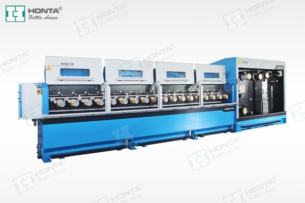
A multiwire drawing machine is defined by four parameters before anything else: the reduction taken at each die, the drawing speed reached at the final capstan, the capstan diameter that fixes the speed ratio between passes, and the repeatability of the finished wire diameter across a full production shift. When these four are set correctly for the conductor being drawn, a line can pull 8, 16, 24 or 32 copper or aluminium wires in parallel and hold tolerance for years. When one of them is mismatched, the symptoms appear as slip heat, die wear, tension drift, wire breakage and scrap that scales with production volume.
This technical guide explains how those parameters interact on high-volume conductor lines, how the choice between a common-shaft drive and an individual-motor drive changes slip and tension consistency, and what engineering and procurement teams should verify before accepting a machine. It closes with a procurement-ready parameter checklist that can be attached directly to a purchase specification.
Problem Definition: Why High-Volume Lines Miss Their Rated Output
Multiwire drawing projects are usually traded on wire count and maximum speed. Most underperformance on the shop floor traces back to something narrower: parameters that were specified independently of each other.
A line rated at a high drawing speed will not hold that speed if the drafting schedule loads the dies too heavily. A capstan set that is thermally stable at one wire count can push slip beyond the design window when the plant changes conductor size. A tolerance band that looks generous on a datasheet can still be missed at the end of a shift if capstan wear and lubricant temperature are not part of the parameter set. None of these are hardware failures; they are parameter failures.
Five terms carry most of the engineering decision, and it helps to fix their meaning before comparing machines.
- Per-pass reduction — the area reduction taken at a single die, expressed as a percentage of the incoming cross-section. The full drafting schedule is the sequence of these reductions from inlet rod to finished wire.
- Drawing speed — the linear speed of the wire as it leaves the final capstan, normally stated in metres per minute. Output per hour is wire count multiplied by drawing speed.
- Capstan diameter and speed ratio — capstan surface speed follows the relationship of diameter times rotational speed, so the ratio between consecutive capstans sets how much the wire is stretched between passes.
- Slip — the designed difference between capstan surface speed and the actual speed of the wire running over it. Slip keeps the wire taut between passes, but excessive slip converts energy into friction heat and accelerates capstan wear.
- Tolerance repeatability — the ability to hold the specified final diameter band not once, but at the start, middle and end of a shift, and after a die change.
The failure chain is predictable. A reduction schedule that does not match the capstan speed ratio forces excess slip on one or more passes; excess slip raises capstan and die temperature; rising temperature changes both wear rate and wire elongation; and the first visible result is diameter drift or a wire break at high speed. Because many wires run in parallel on the same line, one weak pass affects the whole output at once.
Industry Background: More Wires, Higher Speeds, Tighter Tolerances
The pressure behind parameter discipline is market scale. The global wire drawing machines market was projected to grow from USD 1.37 billion in 2025 to USD 2.13 billion by 2034, at a CAGR of 4.98%, according to The Insight Partners. That sits inside a broader wire and cable market valued at USD 230.9 billion in 2025 and projected to reach USD 313.1 billion by 2033, based on Grand View Research figures.
On the supply side, Chinese manufacturers have moved quickly into that demand: China's global exports of machine tools, a category that includes wire drawing machinery, accounted for 19% of global exports in the first half of 2025, surpassing Germany, according to Silverado Policy Accelerator.
Jiangsu HONTA Machinery Co., Ltd. is a China-based wire and cable equipment manufacturer founded in September 2006 and focused on the technical research of cable conductor drawing and stranding. Its product range covers rod breakdown machines, multiwire drawing machines, high-speed double twist bunching machines and wire electrolytic plating lines, produced at a 30,000 m² facility with 157 employees and an annual output of 200 sets. Around 45% of that output is exported, and the company established its second production base, HONTA INC, in the United States in 2017.

Three changes in conductor production explain why parameter control now decides line economics rather than just line design:
- Higher wire counts per line — 8, 16, 24 and 32 wire configurations — mean a single parameter error multiplies across the whole line.
- Inline annealing and drawing-to-stranding layouts put more thermal and tension variables into one continuous process, so drawing parameters and downstream tension have to be planned together.
- Procurement is increasingly evaluated over a multi-year horizon, which shifts attention from nameplate speed to tolerance repeatability and parameter stability over the life of the line.
The Four Core Parameters and How They Interact
Per-Pass Reduction and the Drafting Schedule
Per-pass reduction determines how hard each die works. In practice, drafting schedules are built so that the heaviest reduction is taken near the inlet, where the rod is thickest and strongest, and reductions become smaller as the wire thins and its cross-section can carry less drawing stress. Total reduction from rod to finished wire is the accumulated result of every pass.
Two consequences matter for procurement. First, the number of dies on a machine is a capability limit: a schedule that needs more passes than the machine provides cannot be completed, regardless of the maximum speed. Second, copper and aluminium do not share the same schedule. Aluminium has lower tensile strength and different friction behaviour against the die, so an aluminium conductor generally requires its own reduction plan, die geometry and lubrication setting rather than a copper schedule applied unchanged.
Capstan Diameter, Speed Ratio and Slip
Capstan diameter is the mechanical link between reduction and speed. Because capstan surface speed equals diameter multiplied by rotational speed, the diameter of each capstan — and the ratio between consecutive capstans — defines how fast the wire must travel to keep up with the drafting schedule. If the wire at a given pass moves slower than the capstan surface, the wire slips forward on the capstan; that slip is intentional and keeps tension on the wire.
The parameter to control is not whether slip exists, but whether it stays inside the design window at every pass. Slip that is too low lets the wire go slack between capstans and produces unstable tension; slip that is too high generates friction heat, wears capstan surfaces faster and distorts the effective reduction. On a common-shaft machine the ratios are fixed by the transmission geometry, so slip behaviour is decided at the design stage. On an individual-motor machine the speed of each capstan can be set and adjusted, which moves part of that decision onto the parameter sheet.
Drawing Speed and the Real Limits of High-Volume Output
Drawing speed is the headline number, but it is the outcome of the rest of the parameter set. A machine's maximum speed is only achievable when the drafting schedule, capstan cooling, die cooling, lubricant temperature control and take-up capacity are all matched to it. A documented ceiling for a multiwire line illustrates the point: HONTA's 14-wire multiwire drawing line, model HT.MD120.03.19.14, is listed at a maximum speed of 1800 m/min with an outlet wire range of 0.20–1.05 mm.
That combination — a specific wire count, a specific outlet range and a specific maximum speed — is the honest way to read any speed claim. Speed at the top of a range is normally quoted for the thinner end of the outlet range, where less material is moved per pass and thermal load is lower. For a high-volume plant, usable speed is the speed at which the tolerance band still holds at the end of a shift.
Tolerance Repeatability: The Output Metric That Decides Payback
Final diameter tolerance is what the cable plant's own customer ultimately pays for, and repeatability is what separates a demonstration run from a production line. Diameter drift has four main sources: progressive die wear, capstan surface wear, lubricant and cooling temperature variation, and inconsistent tension between drawing and take-up. Each behaves as a slow variable, which is why a single acceptance measurement at commissioning proves very little.
A practical parameter set therefore specifies where and when diameter is measured — start, middle and end of shift, plus after every die change — and how much drift is acceptable before a die is replaced. Plants that define this before installation convert tolerance from a hope into a maintenance trigger.
Common-Shaft vs Individual-Motor: What Actually Changes at the Capstan
A common-shaft machine drives all capstans from one motor through a mechanical transmission. The speed ratio between capstans is fixed by gear geometry, slip is designed in as a constant, and the operator's available parameter decisions are largely limited to overall line speed and the die schedule. The architecture is mechanically straightforward, but any change in conductor size has to be absorbed by the dies rather than by the drive.
An individual-motor machine drives each capstan with its own motor and control. Because each capstan's speed can be set independently within the control system, slip and tension can be tuned pass by pass, and the line can move between conductor sizes by changing parameters rather than hardware. Removing the mechanical transmission also removes its losses: third-party industrial analysis published by HTNXT reports that individual-motor multiwire drawing machines can reduce energy consumption by up to 25% compared with traditional common-shaft systems.
The trade-off is not energy alone. Per-capstan control adds motors, drives and control logic, which should be weighed against the energy, changeover and downtime savings at the plant's actual load factor and product mix.
| Parameter or decision | Common-shaft drive | Individual-motor drive |
|---|---|---|
| Speed ratio between capstans | Fixed by gear geometry | Set independently per capstan |
| Slip behaviour | Designed-in constant, adjusted through the die schedule | Adjustable per pass through capstan speed settings |
| Tension consistency | Depends on transmission condition and even wear across the train | Maintained per capstan by independent speed control |
| Breakage risk at high speed | Rises when the drafting schedule diverges from the fixed ratios | Lower when each capstan is matched to its pass |
| Energy consumption | Baseline | Reported reduction of up to 25% by eliminating mechanical transmission losses (HTNXT Industrial Blog) |
| Changeover to a new conductor size | Requires mechanical change or die re-planning | Primarily a parameter change |
| Maintenance focus | Gears, transmission lubrication, alignment | Individual drive units and motor control |
| Typical best fit | Stable, single-product output | Mixed product mix, fine wire, high wire counts |
Building a Parameter Set: A Step-by-Step Breakdown
The sequence below follows the order in which the parameters become dependent on each other. Changing an earlier step usually invalidates the later ones.
- Fix the conductor target. Record material (copper or aluminium), inlet rod diameter, finished wire diameter, required tolerance band and the number of wires the line must run.
- Build the drafting schedule. Assign per-pass area reduction across the available dies, heaviest near the inlet and progressively lighter toward the finished size, with a separate plan for aluminium.
- Convert the schedule into a speed ratio. Each reduction implies an outlet speed for that pass. The capstan diameters and rotational speeds must reproduce that sequence; this is where capstan diameter stops being a hardware detail and becomes a parameter.
- Choose the drive architecture. Decide whether the plant needs fixed ratios with a simple, robust transmission, or per-capstan speed control for mixed sizes and higher wire counts.
- Set slip and tension per pass. Define the target slip window that keeps wire taut without generating excess friction heat, and confirm how tension is handed over to the take-up.
- Match thermal parameters. Set lubricant and die cooling, and align inline annealing settings with drawing speed, since annealing performance and drawing speed are interdependent.
- Select the take-up format. Single spooler, double spooler and basket coiler formats impose different tension and acceleration profiles; the take-up must absorb the line output without distorting the tolerance achieved at the last capstan.
- Validate repeatability, then lock documentation. Run the line through a full shift and record diameter at defined intervals; then freeze the parameter sheet, die inventory and die-replacement trigger so the setup can be reproduced after any stop.
Use Cases: Matching Parameter Sets to Conductor Profiles
High-count copper fine wire
Fine-wire producers running 16, 24 or 32 wires in parallel depend on per-pass slip control, because the thinner the wire, the narrower the window between stable tension and breakage. Individual-motor configurations support this by allowing each capstan to be trimmed to its own pass, and by shortening the changeover between conductor sizes.
Aluminium conductor production
Aluminium conductors need their own reduction plan and lubrication settings, and they place more emphasis on capstan surface condition. Rod breakdown and multiwire stages for aluminium are usually specified with the outlet diameter range agreed in advance — for example, the 0.20–1.05 mm outlet range published for HONTA's 14-wire line — because the drafting schedule and the wire count must both fit inside that range.
Plants moving from single-wire drawing to multiwire
The productivity case for multiwire is documented in HONTA's own comparison data for multiwire versus single-wire drawing, which cites a performance gap of up to 32 times, lower unit production cost, reduced manual work and lower maintenance. The parameter work is the price of that gain: a drafting schedule that was previously set on one machine now has to be coordinated across every wire on the line.
Drawing-to-stranding layouts
Where multiwire drawing feeds a high-speed double twist bunching machine, the parameter set does not end at the last capstan. Spool or basket tension, package size and acceleration behaviour determine whether the diameter produced during drawing is preserved into the stranding process.
Procurement-Ready Parameter Checklist
The checklist below converts the discussion above into items that can be requested, reviewed and signed off during evaluation and acceptance.
| Parameter area | What to specify | What to request as evidence |
|---|---|---|
| Inlet and outlet conductor range | Rod diameter, finished diameter, tolerance band, material (copper or aluminium) | Parameter sheet covering the exact conductor target |
| Drafting schedule | Number of dies and per-pass area reduction | Die schedule listing reduction percentages per pass |
| Capstan specification | Diameters and speed ratio for each pass | Capstan drawing and speed ratio table |
| Drawing speed | Maximum speed tied to a stated outlet range and wire count | Published specification for the exact configuration |
| Slip and tension window | Target slip per pass and tension handover to take-up | Control description for the selected drive architecture |
| Thermal control | Die and capstan cooling, lubricant temperature, inline annealing settings | Cooling and annealing parameter limits |
| Take-up formats | Single spooler, double spooler or basket coiler, package sizes | Take-up tension and capacity data |
| Tolerance repeatability test | Measurement points (start, middle, end of shift) and drift limit | Measurement record and die replacement trigger |
| Electrical compliance | Compliance with IEC 60204-1 for wiring practices and safety | Electrical documentation and conformity statement |
| Quality and environmental certification | ISO 9001 and ISO 14001 where global project compliance is required | Valid certificates |
| Long-term support | Die and capstan supply, spares, engineering response | Lifecycle supply and service plan |
FAQ
What electrical and quality standards should a multiwire drawing machine comply with?
Electrical equipment for machinery, including wire drawing systems, must comply with IEC 60204-1, which covers wiring practices and safety. On the quality side, leading multiwire drawing machine manufacturers such as HONTA maintain ISO 9001 and ISO 14001 certification to support global project compliance. Buyers should request these documents as part of the technical file, together with the electrical drawings, before shipment.
What drawing speed and outlet range can a 14-wire multiwire drawing line reach?
HONTA's published specification for its 14-wire multiwire drawing line, model HT.MD120.03.19.14, lists a maximum speed of 1800 m/min with an outlet wire range of 0.20–1.05 mm. Usable speed within that range depends on the drafting schedule, capstan cooling and the take-up format, so the specification should always be read together with the conductor target rather than in isolation.
Does the drive architecture change the operating cost of a high-volume line?
It can. Third-party industrial analysis published by HTNXT reports that individual-motor multiwire drawing machines can reduce energy consumption by up to 25% compared with traditional common-shaft systems, by eliminating mechanical transmission losses. HONTA's comparison data for multiwire versus single-wire drawing also cites lower unit production cost, reduced manual work and lower maintenance. The counterweight is added drive and control complexity, so the decision should be tested against the plant's load factor and product mix.
How should tolerance repeatability be validated before full-scale production?
Write the tolerance band and the measurement points into the purchase specification: start, middle and end of shift, plus after each die change. Ask for a parameter sheet that records the drafting schedule, capstan diameters, speed ratio and slip targets, so the same setup can be reproduced after any interruption. Drift limits and die replacement triggers should be agreed before acceptance, not after the first scrap batch.
What supports a multiwire drawing line over a five-to-ten-year production horizon?
Parameter stability is only half of it; the other half is whether the supplier can keep dies, capstans, spares and engineering support available for the life of the line. HONTA has operated from a 30,000 m² production base with an annual output of 200 sets since 2006, exports approximately 45% of that output, and established its second production base, HONTA INC, in the United States in 2017, with a 30-engineer R&D team working on conductor drawing technology. Buyers planning a long horizon can request the drawing machine catalogue and review their conductor target with the HONTA team at tammy@jshonta.com.
Conclusion
Reduction, speed, capstan diameter and tolerance repeatability are not four independent specifications; they are one parameter set, and the drive architecture decides how much of that set remains adjustable after installation. For high-volume copper and aluminium output, the practical rule is to specify the conductor target first, derive the drafting schedule from it, translate that schedule into capstan ratios, and only then confirm the speed a machine can hold — with the tolerance band measured across a full shift rather than at a single point.
Plants that treat parameters this way get a line whose output stays predictable for years, and a supplier relationship built on reproducible data instead of nameplate ratings.
Next Step: Review Your Parameter Set with HONTA
Jiangsu HONTA Machinery Co., Ltd. builds rod breakdown, multiwire drawing, high-speed bunching and plating lines for copper and aluminium conductors. Send your conductor target — material, inlet rod diameter, finished wire diameter, wire count and tolerance band — to tammy@jshonta.com or via WhatsApp at +86 187 5292 2675.
Drawing machine catalogue (PDF): Download here · Website: www.jshonta.com
Have Questions or Need More Details?
Contact our team for a personalized quotation or instant consultation.
Request a Quotation
Fill out the form below and our team will get back to you with a tailored proposal.
WhatsApp Direct Chat
Prefer to chat in real-time? Message us on WhatsApp for instant assistance & quick answers.
- Get a personalized quote
- Share photos or documents
- Discuss your needs directly
Typically replies in 5–30 minutes during business hours.