
What Is Slip in a Multiwire Drawing Machine? A Guide to Capstan, Die and Tension Selection
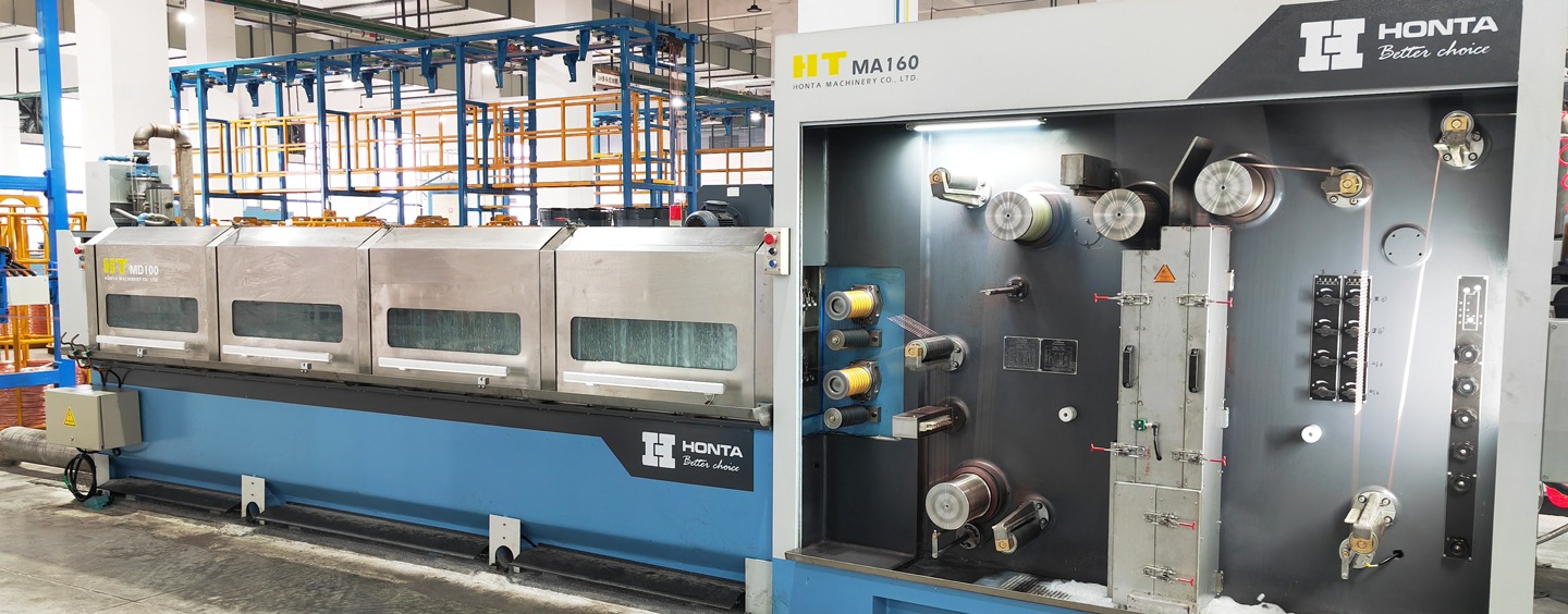
Slip in a multiwire drawing machine is the difference between the linear speed of the wire and the peripheral speed of the capstan it leaves. When that difference is controlled, the wire stays taut and diameter stays stable. When it is not controlled, the symptoms appear as die wear, capstan scoring, diameter drift and wire breaks — most often at the fine end of the range, between 0.18 mm and 0.50 mm. Slip is therefore not a single setting; it is the result of three linked choices: capstan drive, die sequence and tension.
Slip in a Multiwire Drawing Machine: What the Term Actually Means
In drawing practice, slip is expressed as a ratio. For a wire leaving a capstan, the slip ratio compares the wire's actual exit speed (Vw) with the capstan's peripheral surface speed (Vc):
Slip ratio S = (Vw − Vc) / Vc × 100%
Two conditions follow from that definition. Forward slip occurs when the wire moves faster than the capstan surface; the wire is being pulled ahead of the drum by the downstream tension. Backward (negative) slip occurs when the wire moves more slowly than the capstan surface; the drum then scrubs against the wire instead of carrying it.
In general, backward slip is the more damaging of the two. The capstan loses grip, friction heat rises locally, the wire surface can be scored, and the drum itself wears in a ring pattern that is difficult to correct without resurfacing. Forward slip is not automatically safe either: if the downstream tension that creates it is not absorbed by a controlled tension zone, the extra pull thins the wire, distorts the diameter tolerance and eventually breaks it.
On a single-wire machine, slip is a local problem that can often be corrected by adjusting one die or one tension setting. On a multiwire machine the same problem multiplies. A 16-, 24- or 32-wire line runs many wires in parallel through one drawing cabinet, and each wire position has its own die, its own path length and its own wear history. One position drifting into heavy backward slip can break a wire and stop the whole line, while the remaining positions continue to produce conductor that is slightly out of tolerance.
Common causes of slip on multiwire lines
- Elongation mismatch. The die reduction schedule produces a certain elongation per pass; the capstan speed ratio must match it.
- Die wear. As a die wears, the actual reduction and the drawing force change, so the speed balance at that pass changes with it.
- Lubrication and emulsion condition. Friction at the die and at the capstan changes when emulsion concentration, temperature or flow drifts.
- Tension settings. Pay-off, inter-capstan, annealer and take-up tensions all shift the speed balance in their own zone.
- Capstan surface condition. A glazed or ringed capstan grips differently from a freshly finished one.
- Material variation. Copper and aluminium, and annealed versus hard wire, behave differently at the same nominal setting.
Industry Background: Why Slip Moved to the Centre of Machine Selection
Conductor production has shifted toward higher wire counts, higher speeds and finer finished diameters. The HONTA 24-wire multiwire drawing line (HT.MD100.03.27.24) is published with a maximum mechanical speed of 1800 m/min, which illustrates the direction of the category as a whole: more wires running in parallel, faster, with less tolerance for a single position drifting.
At the same time, drive architecture has changed. Individual motor multiwire drawing machines give each capstan its own motor instead of a single motor driving a common shaft through a gear train. An HTNXT technical analysis estimates that individual motor machines can reduce energy consumption by up to 25% compared with traditional common-shaft systems, and notes that the architecture also allows faster die changeover and lower noise, at the cost of higher initial electronics cost. For slip control the practical consequence is significant: with individual motors, the speed relationship between capstans is electronically adjustable, so slip can be trimmed without changing dies. With a common shaft, the ratio is fixed by the gear train, and slip is corrected almost entirely through die selection.
Market context supports the same conclusion. Commercial research cited for the wire drawing machine market puts the global value at USD 3.8 billion in 2025 with a projection of USD 6.1 billion by 2034, which describes an industry investing in capacity rather than retrenching. In that environment, buyers are not only comparing speed and price; they are comparing how easily a machine can be brought back into balance after a die change, a material change or a wear cycle.
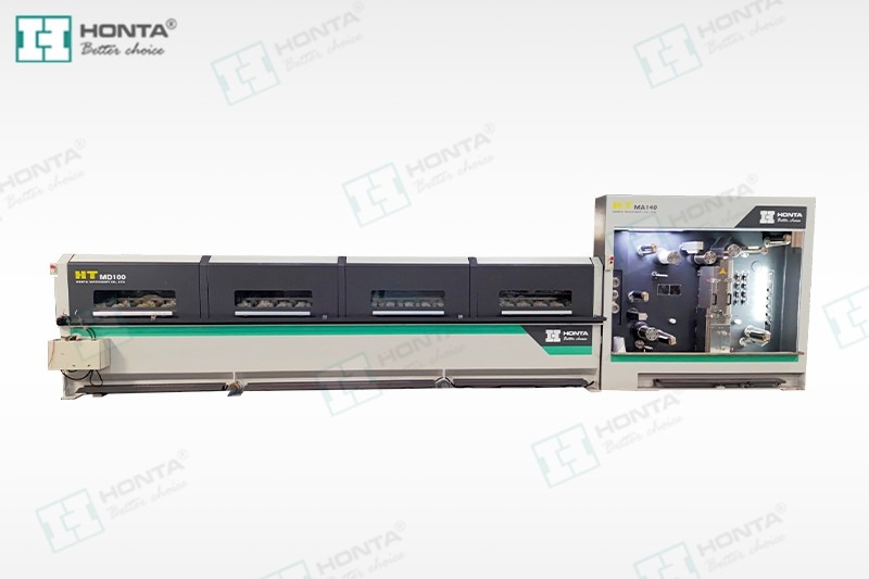
The Detailed Solution: Capstan, Die and Tension as One System
There is no single “slip setting” on a multiwire drawing machine. Slip is the outcome of three selections made together. A machine quoted on speed alone, without a reduction schedule and a tension concept, is a machine whose slip behaviour is still undefined.
1. Capstan selection: what sets the reference speed
The capstan defines the reference speed against which slip is measured, so capstan selection is the first constraint. Four attributes matter:
- Drive architecture. Individual motor drive per capstan allows electronic speed trimming pass by pass; a common shaft with a fixed gear train fixes the ratio and moves the correction burden onto the dies.
- Number of drafts and diameter progression. The number of capstans determines how finely the total reduction is divided between 1.8–2.0 mm inlet rod and 0.18–0.5 mm finished wire on a 16-wire machine.
- Surface material and finish. Grip and wear resistance depend on the capstan surface. This should be specified in writing, together with the wear inspection interval.
- Cooling and alignment. Capstans and die boxes that run hot change dimension and friction; alignment and runout determine whether the wire path is consistent between positions.
Speed capability sets the upper bound. Where a supplier publishes a mechanical maximum such as 1800 m/min on a 24-wire line, that figure describes what the machine can do; it does not by itself define the slip behaviour at that speed, which still depends on the die sequence and tension concept supplied with it.
2. Die selection: what sets the elongation budget
The die sequence converts the inlet diameter into the finished diameter through a series of passes, and each pass produces an elongation. The sum of those elongations must match the speed ratios of the capstans, or slip appears at the pass where the two diverge.
Three die attributes drive the outcome. The reduction per pass must sit inside the machine's ratio window, with even distribution rather than a heavy final pass. The die geometry — approach angle and bearing length — controls drawing force and how well a lubricating film is carried into the deformation zone. The die material and inspection interval determine how quickly the schedule drifts: a worn die changes the effective reduction, and the capstan speed no longer matches it.
On a multiwire machine this becomes a positional issue. Sixteen dies wear at slightly different rates, so after a production run the wires leaving position 1 and position 16 may no longer share the same diameter. Die rotation, scheduled measurement per position and a documented replacement interval are practical countermeasures.
3. Tension selection: what decides forward or backward slip
Tension is the variable that converts a speed mismatch into either forward or backward slip. There are four tension zones, and each has a different job:
- Pay-off tension should be stable and low; fluctuation here propagates through every downstream pass.
- Inter-capstan tension is the main lever. Too high and the wire is pulled ahead of the capstan (forward slip, thinning, breaks); too low and the wire goes slack, loops and cobbles.
- Annealer zone tension applies where an inline annealer sits between drawing and take-up; annealed wire is softer and far less tolerant of over-pull.
- Take-up tension determines spool build and must not stretch finished soft conductor.
Control mode matters as much as the setpoint. On HONTA's wire drawing machines, operation is described as automated or semi-automated under PLC control, with parameter settings entered on a computer screen and automatic tension modes available — the configuration in which tension can be trimmed and repeated rather than re-tuned by hand at every start-up. The published specification for the 16-wire HT.MD100B.16.22D.01 lists a Siemens motor and a Siemens PLC, which is the control platform through which those tension and speed parameters are set.

Step-by-Step: Setting Up and Validating Slip on a Multiwire Line
The following sequence is the order in which slip should be established and then verified. It applies to a new machine being commissioned and to an existing line being re-set for a new conductor size.
- Fix the diameter budget. Record inlet and finished diameter — for example 1.8–2.0 mm inlet to 0.18–0.5 mm outlet on a 16-wire machine — and the number of drafts available.
- Allocate elongation per pass. Divide the total reduction across the passes so that no single pass carries an outsized elongation.
- Convert elongation into capstan speed ratios. Each pass ratio must follow from the elongation of that pass, not from a nominal speed table.
- Match the die schedule to those ratios. Where the die set drifts outside the ratio window, slip is built in before the machine starts. On common-shaft machines this step carries the entire correction.
- Set the four tension zones. Pay-off, inter-capstan, annealer (if fitted) and take-up. Start low and raise inter-capstan tension only until the wire is taut in every zone.
- Run in and measure per position. Measure finished diameter at each position, watch motor current per capstan on individual-motor machines, and inspect wire surface and capstan surface for scoring.
- Correct in the cheapest order. Individual-motor machines allow a speed trim first and a die change second; common-shaft machines allow only the die change. Record what was changed and why.
- Set a wear cycle. Define the die inspection interval per position and the capstan surface check interval, and tie both to a measured diameter trend rather than to a fixed calendar date.

Use Cases: Where Slip Control Decides Product Quality
Slip behaves differently depending on what the conductor is for. Four typical situations:
- Fine copper conductor for electronics and data cables. At 0.18–0.20 mm, forward slip does not show as a diameter problem first — it shows as a wire break. The inter-capstan tension zone and die wear at the final passes dominate.
- Annealed copper for building wire. With an inline annealer between drawing and take-up, the annealer zone tension becomes the controlling variable, because soft wire deforms under a pull that hard wire would tolerate.
- Aluminium conductor. Aluminium responds differently from copper at the same nominal reduction, so the die schedule and the capstan ratio have to be re-derived rather than carried over. Plants running both metals normally keep separate die sets and separate parameter recipes.
- Lines feeding bunching and stranding. Multiwire drawing output usually feeds a downstream bunching or stranding step. Take-up format — single spooler, double spooler or basket coiler — must match that downstream machine, and poor spool build caused by unstable tension reappears as a pay-off problem downstream.
In practice, this is why conductor mills treat slip as a commissioning and maintenance topic rather than a purchase-specification topic alone. A documented supply record illustrates the point: two HONTA wire drawing machine sets supplied to wire and cable factories in the United States, Poland, Portugal, Spain and Türkiye have been running for three years and steadily produce product meeting the customers' requirements, with speed and efficiency cited as the operating highlights.
Comparison: Individual Motor vs Common Shaft for Slip Control
The table below compares the two drive architectures on the dimensions that determine how slip can be corrected. Values are limited to published comparison notes and verified figures; no performance claim is made beyond them.
| Dimension | Individual motor drive | Common shaft (gear drive) |
|---|---|---|
| Speed relationship between capstans | Set per capstan through the drive and control system | Fixed by the gear train |
| Main slip correction method | Speed trim, then die change | Die change |
| Energy consumption | Estimated up to 25% lower than common-shaft systems (HTNXT technical analysis, 2026) | Reference baseline in the same analysis |
| Die changeover | Faster (per published comparison notes) | Slower |
| Noise | Lower (per published comparison notes) | Higher |
| Initial electronics cost | Higher | Lower |
| Typical operational fit | Frequent size changes, fine wire, high wire counts | Long stable runs at one conductor size |
The last row is an editorial reading of the trade-offs above, not a supplier claim: where the conductor mix changes often, electronic ratio adjustment removes the need for a new die set at every change; where one size runs for months, the lower electronics cost of a gear drive may be the more rational choice.
Parameter checklist for comparing multiwire drawing machine designs
| Parameter to specify | Why it matters for slip |
|---|---|
| Wire count and diameter range (8 / 16 / 24 / 32 wires; e.g. 1.8–2.0 mm inlet, 0.18–0.5 mm outlet) | Defines how finely the reduction must be divided |
| Capstan drive architecture | Determines whether slip is corrected electronically or by die change |
| Capstan surface material and wear inspection interval | Grip consistency between positions |
| Die reduction schedule and die inspection interval | Controls elongation match per pass |
| Tension control mode (automatic tension modes, PLC parameter entry) | Determines whether settings can be repeated run to run |
| Annealer integration and take-up format (single spooler, double spooler, basket coiler) | Adds tension zones that must be balanced with the drawing cabinet |
| Motor and PLC platform | Determines response speed of the speed and tension loops |
| Pre-shipment testing scope (HONTA: 100% test) | Evidence that the machine was balanced before dispatch |
| Compliance documentation (CE, applicable standards) | Electrical and safety design basis of the control system |
FAQ: Slip, Compliance and Supplier Verification
1. Which certification and standards apply to a multiwire drawing machine supplied into the EU?
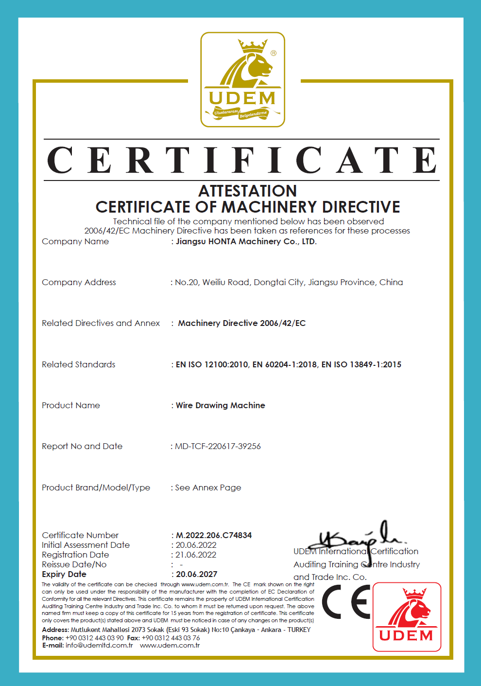
HONTA holds CE certification under CE-MD, certificate number M.2022.206.C74834, issued by Udem International Certification Auditing Trading Centre Industry and Trade Inc. Co. on 2020-06-20 and valid to 2027-06-20 for the scope “wire drawing machine”. The listed standards are Machinery Directive 2006/42/EC, EN ISO 12100:2010, EN 60204-1:2018 and EN ISO 13849-1:2015. Because the tension and speed loops on a multiwire machine are electrical control functions, EN 60204-1 and EN ISO 13849-1 are the parts of that list most directly connected to slip control hardware. ISO 9001 and ISO 14001 certification and IEC 60204-1 compliance have also been reported for HONTA in third-party coverage.
2. How can a buyer verify that a supplier can actually control slip across 16 or 24 wire positions?
Ask for the engineering basis and the test evidence, not only the speed figure. HONTA maintains a 30-engineer R&D team working on cable conductor drawing and stranding technology, applies 100% testing to its output, and offers ODM production with customization of colour and component model types. On the machine side, the 16-wire HT.MD100B.16.22D.01 is specified with a Siemens motor and a Siemens PLC, and operation is described as PLC-controlled with computer-screen parameter settings and automatic tension modes — the configuration in which per-position speed and tension can be set and repeated. Ask to see the parameter record and the diameter measurements taken at each position during the factory test.
3. Does better slip control change the cost of the machine?
It changes the cost structure rather than simply the price. An individual motor architecture carries higher initial electronics cost than a common-shaft gear drive, but the same comparison notes faster die changeover and lower noise, and an HTNXT technical analysis estimates up to 25% lower energy consumption for individual motor machines. Against that, a fixed-ratio machine shifts cost into die sets and changeover time whenever the conductor size changes. HONTA's commercial terms are configuration-based: MOQ is one set, monthly capacity is 15 sets, and export markets include the EU, the Middle East and Africa, so the quotation should be requested against a defined wire count, diameter range and drive architecture rather than as a generic price.
4. Can we validate slip behaviour on our own rod before committing to a full line?
Validation is a documented process rather than a single sample. With a one-set MOQ and ODM customization available, the practical route is to define the conductor recipe (inlet and outlet diameter, wire count, material, annealer or not) and ask for the factory test data for that recipe — diameter per position, motor current per capstan and the die schedule used. Buyers should also confirm the after-sales route, since HONTA provides both remote and on-site support; the service model matters because most slip corrections after commissioning are made at the plant.
5. What lead time should be planned for a multiwire drawing machine?
HONTA's stated lead time is 90 days, with a monthly capacity of 15 sets and a minimum order quantity of one set. For planning purposes, the die sets, spare capstans and the commissioning window should be scheduled against that 90-day figure rather than after the machine arrives, because the first reduction schedule and the first die replacement interval are established during commissioning. Buyers can request a configuration-based quotation and a current catalogue to start that planning.
Conclusion
Slip is the measurable gap between how fast the wire moves and how fast the capstan surface moves, and on a multiwire drawing machine that gap is never decided by one component. The capstan architecture sets the reference speed and determines how the correction will be made. The die schedule sets the elongation budget that the capstans must match. Tension decides whether a mismatch turns into harmless forward slip or damaging backward slip. Buyers who specify those three items together — and who ask for per-position test data rather than a single headline speed — are comparing machine designs on the variable that actually governs conductor quality.
HONTA (Jiangsu HONTA Machinery Co., Ltd.) was founded in September 2006 and works on cable conductor drawing and stranding technology from a 30,000 m² facility with 157 employees, a 30-engineer R&D team and an annual output of 200 sets; it established HONTA INC, a second production base in the United States, in 2017. Its product range covers copper and aluminium rod breakdown lines, multiwire drawing lines, high-speed double twist bunching machines and wire electrolytic plating lines, with 45% of output exported to the USA, the Middle East, Africa and Asia.
Next step: put your conductor recipe against a machine configuration
Send us your inlet and outlet diameter, wire count, material and annealer requirement, and we will respond with the matching configuration, die schedule outline and factory test data. Catalogue of drawing machines available for download.
Download the HONTA drawing machine catalogue (PDF)
Email: tammy@jshonta.com | Tel: 0086 182 6287 9467 | WhatsApp: +8618752922675 | www.jshonta.com

Have Questions or Need More Details?
Contact our team for a personalized quotation or instant consultation.
Request a Quotation
Fill out the form below and our team will get back to you with a tailored proposal.
WhatsApp Direct Chat
Prefer to chat in real-time? Message us on WhatsApp for instant assistance & quick answers.
- Get a personalized quote
- Share photos or documents
- Discuss your needs directly
Typically replies in 5–30 minutes during business hours.