
Wire Breaks on a Multiwire Drawing Machine: A Diagnostic Path
Repeated wire breaks on a multiwire drawing machine can stop a conductor line faster than almost any other fault, and the first reaction on the floor is usually to blame the drawing section. That reaction is understandable. It is also frequently premature.
A break is not a cause. It is the last event in a chain that starts at the rod coil and ends at the spool. The path below works that chain in order — incoming rod, pay-off and entry tension, dies and lubrication, capstan slip and drive architecture, inline annealing, take-up and spooling, then the control records that connect them — so maintenance and process engineers can isolate one variable at a time. Isolating variables matters more than finding a culprit quickly: a line adjusted in five places at once may stop breaking for a week and still never reveal what was wrong.
What a repeated wire break is actually telling you
Every break leaves three pieces of evidence before anyone touches a setting: its location, its appearance, and its timing. Collected across twenty or thirty breaks, those three records describe the fault far better than any single observation.
- Location. Which wire position, and where along the line: after the die, at a capstan, inside the annealer, between annealer and take-up, or on the spool.
- Appearance. A drawn-down, necked end suggests the wire was thinning before it parted. A cup-and-cone fracture points in a different direction from a brittle, granular break. Arc marks or discoloration implicate the annealer. A flattened or kinked end suggests take-up.
- Timing. Whether the break follows start-up, a speed change, a die change, a rod lot change, or a lubrication top-up.
The pattern usually sorts itself into one of two families. Breaks that repeat at the same position are position-specific: one die, one capstan, one annealer sheave, one guide. Breaks that migrate across positions are usually shared: the rod supply, the emulsion, the annealer power supply, or the line's tension control. A single break is an event. A repeated break is data.
Why multiwire lines amplify small disturbances
A multiwire drawing machine draws several wires in parallel from a common arrangement — 8 wires, 16 wires, 24 wires or 32 wires depending on the model — and that parallel architecture is what makes diagnosis different from a single-wire machine.
Every wire in the line shares the same rod supply, the same emulsion circuit, the same annealer power source and the same take-up concept. A disturbance that would produce one break on a single-wire machine can therefore produce a cluster on a multiwire line, because more parallel paths must stay inside the same window. The same logic applies to wear: eight dies wear together, and one position reaching its limit first is easy to miss when the other seven still look acceptable.
Speed raises the stakes. HONTA's published specification for its 24-wire multiwire drawing line (HT.MD100.03.27.24) lists a maximum mechanical speed of 1,800 m/min, according to the Honta India product page, and at that speed the interval between slightly out of tolerance and broken wire shortens considerably.
Exit diameter matters just as much. HONTA's 16-wire model HT.MD100B.16.22D.01 is specified for an inlet wire diameter of 1.8–2.0 mm and an outlet of 0.18–0.5 mm, with Siemens motors and a Siemens PLC. Fine wire in that range has very little tolerance for a rough capstan, a worn die, or a tension spike at start-up.
Drive architecture changes how a fault behaves. Individual-motor multiwire drawing machines give each capstan its own motor, so one position can be trimmed without disturbing the rest of the line; documented comparisons of individual-motor and common-shaft designs also note faster die changeover and lower noise for the individual-motor arrangement, against higher initial electronics cost, and an HTNXT technical comparison estimates energy savings of up to 25% compared with common-shaft systems. On a common-shaft machine, by contrast, a single incorrect die affects the tension balance across the whole group — which is why the same break symptom can demand a very different first check.
The diagnostic path at a glance
Work the checkpoints in order and pause at the first one where the evidence is inconsistent. The sequence is deliberate: each step removes a variable that would otherwise contaminate the interpretation of every step after it.
- Incoming rod condition.
- Pay-off and entry tension.
- Dies and lubrication.
- Capstan, slip and drive architecture.
- Inline annealer.
- Take-up, spooling and coiling.
- Control records and the break log.
If the multiwire line is fed from a copper rod breakdown machine or an aluminium rod breakdown machine rather than from bought-in rod, the upstream line becomes part of the same chain and should be checked with the same discipline, whether it is a rod breakdown with annealer machine for copper and aluminium or a separate breakdown stage feeding the multiwire cabinet.
Checkpoint 1 — Incoming rod condition
Start upstream, because a rod defect cannot be drawn out of the wire later. Rod arrives with a diameter tolerance, a surface condition, a temper and a coil geometry, and any of the four can generate breaks many stands downstream.
- Surface defects. Seams, slivers, cracks, inclusion streaks and heavy roll marks act as stress raisers. They often survive the early passes and fail where the wire is thinnest.
- Oxide and contamination. Scale and residual drawing soap interfere with lubrication and accelerate die wear, which then produces secondary breaks that look like die faults.
- Coil geometry. Crossed layers, tangles and collapsing coils create tension spikes at the pay-off that no die schedule can absorb.
- Temper consistency. Rod that is harder or softer than the die schedule assumes changes the load on every capstan in the line.
The practical action is a rod lot log kept alongside the break log. When breaks cluster after a lot change, the question stops being which die failed and becomes which coil arrived.
Checkpoint 2 — Pay-off and entry tension
Entry tension is the quietest variable on the line and one of the most disruptive. Because every wire shares the same pay-off arrangement, a single tension spike can break several positions within seconds — a signature that is easily misread as a machine fault.
Check the pay-off brake or dancer response, the accumulator travel, roller and guide alignment, wire path length, and worn ceramic guides that scuff rather than guide. On coil pay-off, look for layer adhesion and tangles. On spool pay-off, check for spool damage and over-run at stop. Then compare break timestamps with coil-change timestamps; a correlation here closes the case quickly.
Checkpoint 3 — Dies and lubrication
Dies and lubrication belong in one checkpoint because neither can be judged without the other. A worn die in a well-lubricated box behaves differently from a good die in contaminated emulsion, and the wire surface shows which condition is present.
Inspect die bearing length, ovality, ring cracks and die-holder alignment to the capstan. Verify the reduction per pass against the schedule the machine was set up for, and resist the temptation to alter that schedule on the floor without the builder's data — on a multiwire line the schedule is a system, not a per-die decision. On the lubrication side, check emulsion concentration, temperature, flow, filtration and contamination, plus carry-over between boxes.
Read the wire, too. Longitudinal scratches point to a damaged die or guide; a bright, polished surface can indicate a lubrication film that is too thin; periodic marks suggest a capstan or sheave rather than a die. None of these observations identifies a cause on its own, but each narrows the search.
Checkpoint 4 — Capstan, slip and drive architecture
Slip is the difference between the wire speed the capstan surface implies and the speed the wire actually travels. It generates heat, accelerates capstan wear and produces breaks that look like simple tensile failures, which is why capstans are so often blamed first and confirmed last.
Inspect capstan surface finish and diameter, groove condition, wire wrap and lateral wander. A polished or scored ceramic capstan loses grip; a capstan running with the wrong die sequence is asked to deliver a reduction it was not sized for. Both raise slip without any obvious change in machine behaviour.
Drive architecture decides how quickly a fault can be localised. On an individual motors multiwire drawing machine, each capstan can be trimmed independently, so a suspected position can be adjusted and observed without touching the rest of the line. On a common-shaft machine, one incorrect die shifts the tension balance across the whole group, so the correction returns to the schedule rather than to a single drive. Knowing which architecture is installed prevents the most common diagnostic error on multiwire lines: treating a system imbalance as a single-position fault.
Checkpoint 5 — The inline annealer
An inline annealer machine sits between drawing and take-up, and it can imitate faults from both ends of the line. Over-annealed wire becomes soft and elongates under take-up tension; under-annealed wire stays hard and fails at the next bend. In both cases the break may physically occur at the take-up while the cause sits at the contact sheaves.
Inspect contact sheaves and rollers for pitting, arc marks, flat spots and build-up. Verify electrical contact consistency across all wires, since one poor contact changes the thermal history of a single position. Check wire path stability through the annealer, cooling, and any protective atmosphere or steam supply. If the break position corresponds to one contact sheave, the fault is localised and the fix is usually mechanical rather than electrical.
One diagnostic habit is worth building here: record the annealer settings with every break. A break log without annealing data cannot separate a drawing problem from a thermal one.
Checkpoint 6 — Take-up, spooling and coiling
Take-up is where a drawing or annealing problem finally becomes visible, so it attracts blame out of proportion to its role. The take-up family matters for diagnosis: a single spooler, a double spooler and a basket coiler each have their own tension behaviour, traverse logic and failure modes.
- Tension versus line speed. Tension that does not track acceleration produces start-up breaks and stop-mark elongation.
- Dancer and accumulator response. Slow response shows up as periodic tension oscillation rather than a single failure.
- Traverse and lay. Poor lay causes wire crossing and crushing inside the package.
- Spool and basket condition. Damaged flanges, rough basket liners and worn guide rolls damage wire that was drawn correctly.
Breaks found inside the package, with crushed or kinked wire, are spooling faults. Breaks with a necked end that happen before the package are not. Distinguishing the two prevents a great deal of unnecessary work on the drawing section.
Checkpoint 7 — Control records and the break log
Modern lines record their own evidence. On a machine such as the HT.MD100B series, the Siemens PLC logs alarms, speeds, tensions and motor currents, and parameter changes made through the computer-screen interface are traceable to a time and an operator.
Capture that data before clearing alarms. Then compare break timestamps against speed, tension and current trends, and against parameter changes. A break that appears within seconds of a speed ramp is a control-response question; a break that appears ten minutes after a speed change is more likely thermal or wear-related.
Keep the log simple and keep it in one place: time, wire position, location along the line, line speed, rod lot, die set, emulsion status and annealer settings. Twenty entries of that kind are worth more than any single inspection.
Matching the break signature to the stage
The table below is a diagnostic heuristic, not a verdict. Use it to decide where to look first, then confirm with the checkpoints above.
| What you observe | First place to look | Confirming check |
|---|---|---|
| Breaks repeat at one wire position, similar length of wire drawn each time | Die, capstan or guide on that position | Move the die to another position and see whether the fault follows the die or stays in the position |
| Breaks migrate randomly across positions | Shared supply: rod lot, emulsion, annealer power | Align break timestamps with rod lot, emulsion and annealer records |
| Breaks at start-up or immediately after a speed change | Tension and acceleration response | Watch dancer, accumulator and take-up tension during the ramp |
| Wire necks down and parts just before the take-up | Annealer contact or final die and take-up tension | Check sheave condition, per-wire contact and take-up tension tracking |
| Break at the annealer showing arc marks or discoloration | Electrical contact at the annealer sheaves | Inspect sheave surface and contact consistency wire by wire |
| Break inside the package with crushed or kinked wire | Take-up, traverse or spool condition | Review lay pattern, traverse timing and spool or basket condition |
| Breaks on aluminium rod early in the line | Rod surface condition and lubrication | Inspect rod handling, die approach and emulsion condition for aluminium |
Two scenario walk-throughs
Two conditional examples show how the path is applied. They are illustrative patterns, not reports of specific customer cases.
Pattern A: one position on a 24-wire line breaks only at high speed. If the fault stays in the same position after the die has been swapped, the die is not the cause and attention moves to that capstan and its guide. If the break disappears when that position runs at reduced speed, slip or cooling at that capstan becomes the leading hypothesis. If the fault follows the die to its new position, the die itself — wear, ovality or alignment — is confirmed, and the whole die set should be reviewed rather than the single item replaced. The order of those three tests is what prevents the line from being adjusted in three places at once.
Pattern B: breaks appear across several positions after a rod lot change on an aluminium line. A shared pattern points away from dies and capstans. Rod surface condition, oxide and temper consistency move to the front of the queue, followed by emulsion condition, because aluminium handling and lubrication differ from copper practice. If the pattern disappears when the previous lot is reintroduced, the line has answered the question without any machine adjustment. If it persists across lots, the annealer supply and take-up tension response become the next candidates.
In both patterns the same principle applies: change one variable, observe, and record the result. The value of a structured path is not that it always names the fault immediately, but that it leaves a trace of what has already been excluded.
Diagnostic work on a multiwire drawing machine is a records exercise as much as a mechanical one: parameter history, break location and timing decide which checkpoint to open first.
What to prepare before you contact a supplier
Most supplier conversations about repeated breaks become productive or unproductive in the first five minutes, depending on what the mill brings to them. A supplier cannot reconstruct a line's behaviour from a description of one break, but a well-prepared data set often narrows the cause before any site visit is discussed.
- Machine identity. Model and configuration, including wire count and whether the drives are individual motors or common shaft.
- Product data. Inlet and outlet diameters, material, and the die schedule currently in use.
- Break log. Time, wire position, location along the line, line speed at failure, and the appearance of the fracture.
- Process records. Rod lot numbers, emulsion concentration and temperature, annealer settings, take-up tension values.
- Control data. Alarm history and parameter changes around the failure window.
- Photographs. The break itself, the capstan or sheave surface, and the package where the wire was spooled.
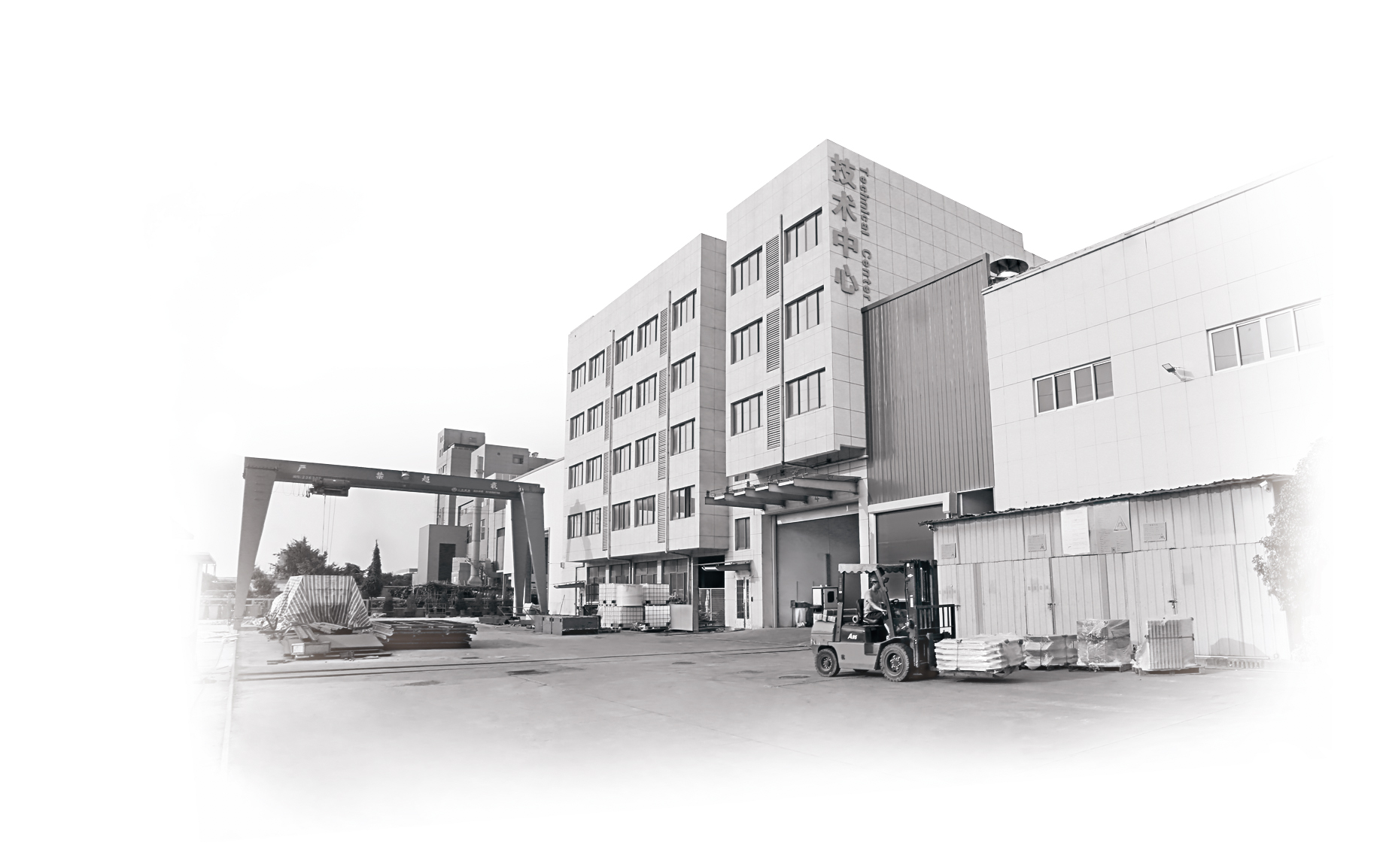
Jiangsu HONTA Machinery., Ltd. (www.jshonta.com) has worked in cable conductor drawing and stranding research since 2006, and the questions its engineering team asks about a break report follow the same sequence described above. The company operates a 30,000 square metre manufacturing facility with approximately 157 staff, an R&D team of 30 engineers and an annual production capacity of 200 sets, and it established a second production base, HONTA INC, in the United States in 2017. Its product range covers rod breakdown machines, multiwire drawing line series, high-speed double twist bunching machines and wire electrolytic plating lines — the surrounding wire and cable equipment that determines how a drawing fault propagates into a finished conductor.
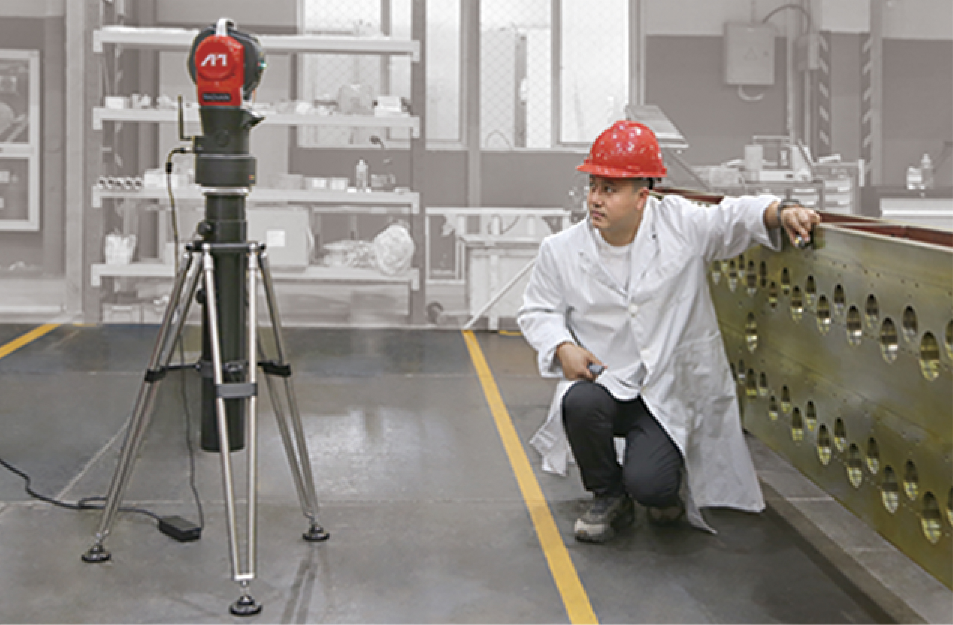
Verification before shipment is where a machine's baseline is set; a documented baseline makes later fault isolation faster.
Frequently asked questions
What is the most common cause of wire breaks on a multiwire drawing machine?
No single cause is most common across all lines, and a supplier who names one without data is guessing. A break is a chain event, so the reliable approach is to work the checkpoints in order — incoming rod, pay-off tension, dies and lubrication, capstan slip, inline annealing and take-up — and stop where the evidence becomes inconsistent.
How can I tell whether a break started at the die or at the annealer?
Look at the fracture and the position. A die-origin break typically shows a drawn-down, necked end with die or scratch marks and occurs at the same wire position each time. An annealer-origin break often shows arc marks, discoloration or a soft stretched section, and appears close to the contact sheaves. Moving the suspect die to another position is the quickest confirmation: if the fault follows the die, the die is the cause.
Does running 24 or 32 wires instead of 16 change the break risk?
It changes the number of parallel paths that must stay inside the same process window. More wires share the same rod supply, emulsion circuit, annealer power source and take-up, so a shared disturbance can produce a cluster of breaks rather than one. Position-specific faults are also harder to spot, because one worn die or capstan can hide among many acceptable ones.
Can the same multiwire drawing machine run both copper and aluminium rod?
Whether a given machine can run both materials depends on its specification, and the answer should come from the model documentation rather than from general practice. HONTA builds copper and aluminium RBD lines as well as multiwire drawing line series, and each model carries its own documented inlet and outlet diameter range — for example, the 16-wire model HT.MD100B.16.22D.01 is specified for 1.8–2.0 mm inlet and 0.18–0.5 mm outlet. Aluminium also requires its own die schedule, lubrication practice and rod handling discipline.
Does compliance documentation help when troubleshooting?
Compliance does not identify a break cause, but it does establish a baseline. HONTA holds ISO 9001 and ISO 14001 certifications and complies with the IEC 60204-1 electrical safety standard, as reported by The National Law Review in October 2026. A machine built and documented against a known baseline gives maintenance teams a reference point for parameters, wiring and safety functions, which shortens the time spent questioning whether a reading is normal.
What should I prepare before contacting HONTA about repeated breaks?
Bring the machine model and configuration, inlet and outlet diameters, the die schedule, a break log with time, wire position, location and line speed, plus rod lot numbers, emulsion data, annealer settings, take-up tension values and control alarm history. Photographs of the fracture, the capstan surface and the finished package are valuable. Send that package to Tammy, International Trade Department Manager, at tammy@jshonta.com, by phone on 0086 182 6287 9467, or through WhatsApp on +8618752922675. The company's drawing machine catalogue is available for download at the HONTA catalogue page and lists the multiwire and rod breakdown configurations a line audit would cover.

A complete break report shortens the distance between a shop-floor symptom and a confirmable cause.
Conclusion
Wire breaks on a multiwire drawing machine rarely come from the component that receives the blame. They come from a variable that drifted out of its window somewhere between the rod coil and the spool, and the line will keep producing them until that variable is found. Working the seven checkpoints in order — rod, pay-off, dies and lubrication, capstan and drive architecture, annealing, take-up, and control records — converts a frustrating symptom into a sequence of exclusions, each one documented in a break log that makes the next conversation with a supplier far more productive.
Have Questions or Need More Details?
Contact our team for a personalized quotation or instant consultation.
Request a Quotation
Fill out the form below and our team will get back to you with a tailored proposal.
WhatsApp Direct Chat
Prefer to chat in real-time? Message us on WhatsApp for instant assistance & quick answers.
- Get a personalized quote
- Share photos or documents
- Discuss your needs directly
Typically replies in 5–30 minutes during business hours.