
Induction Heater Control Board Explained: Frequency Tracking, PID, and Protection Basics
An induction heater control board is the power-conversion and regulation stage of an induction heating system. It turns mains AC into high-frequency current, drives the resonant tank that feeds the induction heating coil, and regulates output so the load holds a set temperature. In most industrial installations the board, rather than the coil, decides how tightly the process holds setpoint, how quickly the system reacts to a load change, and what happens when a fault occurs.
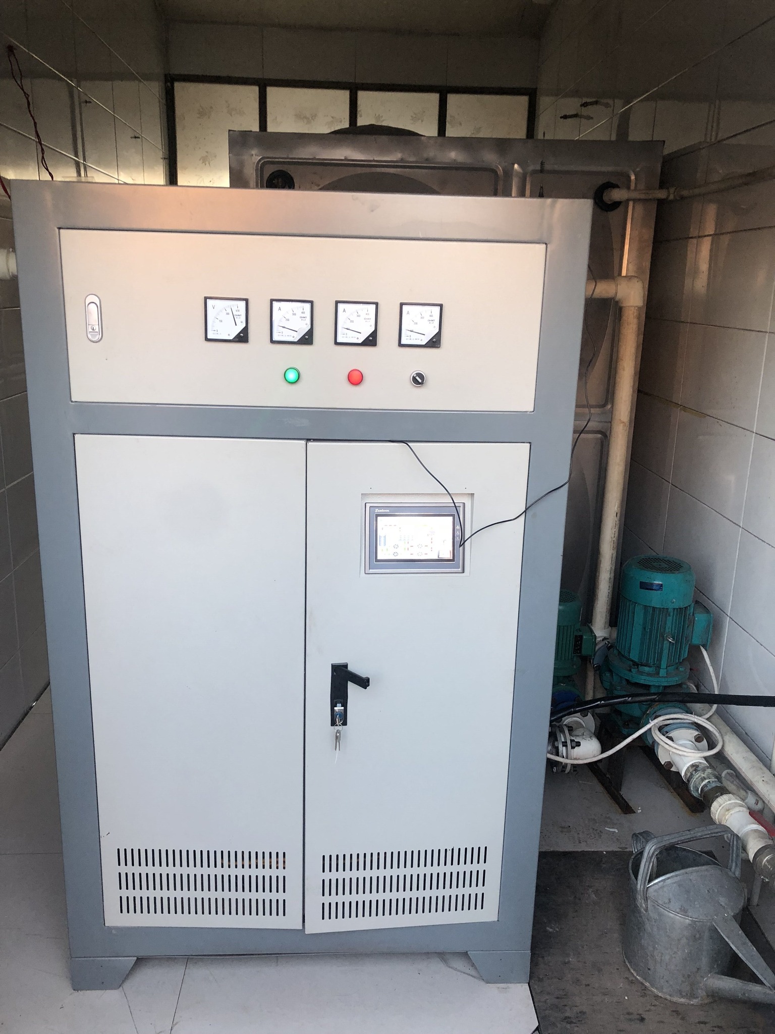
The control board sits between the mains supply and the induction heating coil. The JONSON JS1300-10/15 used as the reference example in this article is a single-phase full-bridge 8 kW board rated for 220 V / 50 Hz input.
Problem Definition: Why the Control Layer Decides the Outcome
Industrial buyers normally compare induction heating equipment on kilowatts, coil dimensions and purchase price. The specifications that determine uptime and process quality sit one level deeper, inside the control board, and they show up as three recurring problems.
Problem 1 — the resonant point moves while the system runs. The induction heating coil changes resistance as it heats, the workpiece changes permeability as it passes through temperature transitions, and every coil geometry presents a different inductance. A drive that runs at a fixed frequency, or that was tuned by hand at commissioning, drifts away from resonance as soon as the load changes. Off resonance, the tank current rises, efficiency drops and the switching devices run hotter.
Problem 2 — power granularity limits what the process can do. Contactor-based or step-switched control offers full power or nothing. That produces overshoot on heat-up, thermal cycling on hold, and scrap in processes where the temperature band is narrow, such as plastics and rubber, chemical reactions or metal heat treatment.
Problem 3 — fault energy is faster than mechanical protection. At 8 kW, a shoot-through event or a coil short produces a current rise that reaches destructive levels well before a mechanical protective device has reacted. Presence of protection is not the question; response time is.
All three are design problems rather than operating problems. They are solved in the control board or they are not solved at all, which is why the board deserves the same scrutiny as the coil during supplier evaluation.
Industry Background: Why Control Moved From Analog to DSP
The global induction heating system market was valued at USD 2.39 billion in 2024 and is projected to reach USD 4.5 billion by 2035 (WiseGuyReports). As of mid-2024, more than 550,000 induction heating systems were deployed globally, with the Asia-Pacific region accounting for around 40% of the total installed base, approximately 220,000 units (Global Market Insights). The 10 kW to 100 kW power segment dominates the market because of its versatility in applications such as automotive part hardening, forging and brazing (MarketsandMarkets), which is the band in which most industrial control boards of the 8 kW class operate.
Efficiency is the commercial argument behind that growth. Induction heating systems achieve energy efficiencies up to 92%, with an average cycle time reduction of around 30% compared with traditional gas or resistance-based heating (Global Market Insights). None of that performance is delivered by the coil alone. It depends on the drive staying at resonance and on the temperature loop holding setpoint without oscillation.
Safety expectations moved at the same time. Industrial induction heating equipment must comply with IEC 60519-1, the general requirements for electroheating installations, and IEC 60519-3, the particular requirements for induction heating and melting. Those standards place isolation, protection coordination and fault behaviour inside the scope of the machine assessment, which brings the control board into the compliance conversation rather than leaving it as an internal component.
JONSON is the brand of Guangdong Jiangxin Electronic Technology Co., Ltd., an induction heating equipment manufacturer founded in 2011 and based in Shunde District, Foshan City, Guangdong Province, China. The company operates a 3,000 m² factory with more than 60 employees, produces around 120,000 units per year, maintains a 30+ engineer research and development team, and exports roughly 40% of its output to markets that include Europe, the United States, India and Indonesia. Its product range covers induction heaters, induction heating control boards, induction heating coils, water boilers, hot air generators and steam generators.
The Solution: What a DSP Control Board Actually Does
A modern induction heater control board combines four functions in one unit: a switching bridge that converts DC into high-frequency AC, a frequency-tracking loop that keeps the bridge at the resonant point, a power-regulation stage that accepts a remote setpoint, and a protection layer that acts faster than the fault it is guarding against. The sections below take each function in turn, using the JS1300-10/15 single-phase full-bridge 8 kW control board at 220 V / 50 Hz as the working example.
Main Circuit: Series Resonance and Bridge Topology
In a series-resonant design, the induction heating coil acts as the inductor and a resonant capacitor forms the series tank. At resonance the tank presents its lowest impedance and the current approaches a sinusoid, which allows the bridge to switch close to the zero crossing of the voltage across the devices and keeps switching losses low. The topology that surrounds that tank separates one board class from another.
A half-bridge uses two switching devices across a split DC bus. Each device blocks approximately half of the DC bus voltage, which makes the arrangement attractive for compact and lower-power units, at the cost of split-capacitor balancing and a tank that sees only half the bus voltage.
A full-bridge uses four devices and applies the full DC bus voltage to the tank. For the same bus voltage and the same tank impedance it delivers substantially more power than a half-bridge, which is why it is the usual choice when a meaningful output must be extracted from a single-phase supply. The trade-off is two additional devices plus stricter dead-time and shoot-through management on both legs. The JS1300-10/15 sits in that category: a single-phase full-bridge board rated 8 kW with a 220 V / 50 Hz input.
Frequency Tracking: DSP-Based High-Speed Automatic Phase-Locking
Frequency tracking is the function that keeps a resonant system resonant. The control variable is the phase difference between the tank voltage and the tank current. A digital signal processor samples that phase relationship at high speed and corrects the drive frequency continuously so the bridge stays locked to the load, a technique described as high-speed automatic phase-locking.
The practical consequence for a buyer is that commissioning does not depend on an engineer finding the right frequency by hand, and operation does not depend on that frequency staying valid. When the coil heats up, when a different workpiece size enters the coil, or when a replacement coil of similar geometry is fitted within the validated range, the tracking loop re-locks instead of the system detuning. The failure pattern this removes is common in manually tuned equipment: the drive is optimised for a cold load and then runs off resonance once the load reaches working temperature.
Power Regulation: 20%–100% Stepless and 0–5 V PID Adjustment
The JS1300-10/15 provides 20% to 100% stepless power regulation, a continuous adjustment range rather than a set of fixed steps. A stepless range of that width allows a heating profile to ramp, soak and hold without switching the output on and off, which is what protects product quality in narrow-band processes and reduces thermal shock on the coil and on the load.
External control is handled through 0–5 V PID adjustment. The board accepts a 0–5 V analogue signal from a host PLC or a dedicated temperature controller, and the PID loop varies output to close the gap between measured and set temperature. In practice the three terms do different work: the proportional term responds to the present error, the integral term removes the steady-state offset that remains after the proportional action settles, and the derivative term damps overshoot when the load approaches setpoint. The board executes the loop; the tuning determines whether the result is a flat hold or a slow oscillation.
What the loop acts on is the measured load temperature, and the JS1300-10/15 specifies a load temperature detection accuracy of ±1 °C. That figure describes the measurement resolution available to the controller. Sensor placement and the thermal lag between sensor and load remain the practical limits on achievable control quality, so the ±1 °C figure should be read as the accuracy of the input, not as a guarantee of the whole process band.
Protection: Fully Electrically Isolated Soft Start and ≤2 µS Overcurrent Trip
Protection is where the specification list becomes a purchasing argument. Three figures matter most on this board.
Fully electrically isolated soft start. The control side is galvanically separated from the power side, and the output ramps up instead of switching full current at the first instant. That removes inrush stress from the switching devices and limits the disturbance seen by the customer supply, which matters when a plant runs several units from the same distribution board.
≤2 µS instantaneous overcurrent protection. The board reacts inside the timescale of the fault itself, interrupting the drive before the fault current has time to build into device destruction. This is the difference between a protection layer that records an event and one that prevents it.
Start time under 1 second. Full output is available in less than a second from the start command. In multi-batch cycles this shows up as throughput rather than as a headline specification, because every restart that takes seconds instead of a fraction of a minute adds up across a shift.
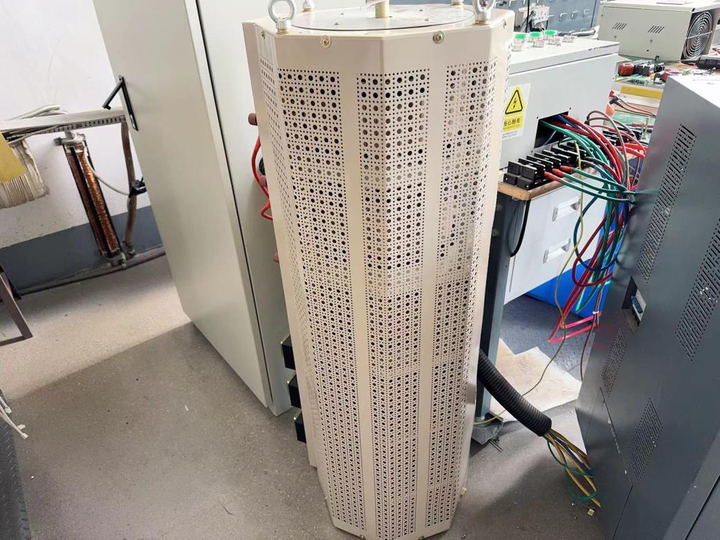
Board-level testing before assembly: protection thresholds, phase-locking behaviour and temperature input accuracy are verified as part of the equipment test routine.
Step-by-Step: How a Heating Cycle Runs Through the Board
The sequence below describes what happens inside an induction heating system from power-up to steady hold. It is also a useful checklist during FAT, because each step can be verified independently.
- Mains conditioning and DC bus. The 220 V / 50 Hz single-phase input is rectified and smoothed into a DC bus. Bus stability at this stage determines how cleanly the bridge can switch later.
- Isolation and soft start. The control side is electrically isolated from the power side, and the output is ramped rather than switched. No inrush current is drawn at the first instant.
- DSP generates the drive pattern. The processor produces the switching pattern for the full bridge, including dead time on both legs to prevent shoot-through.
- The bridge inverts to high frequency. Four devices convert the DC bus into high-frequency AC, which is applied to the series tank formed by the resonant capacitor and the induction heating coil.
- Phase detection closes the tracking loop. Tank voltage and current are sensed, the phase difference is calculated, and the drive frequency is corrected so operation stays at resonance as the load heats.
- Power follows the setpoint. The 0–5 V PID signal defines the required output, and the board adjusts power steplessly anywhere between 20% and 100%.
- Temperature feedback closes the process loop. The measured load temperature, detected to ±1 °C, is compared with setpoint and the PID output corrects the power command.
- Protection supervises throughout. The overcurrent comparator is armed continuously, with a response time of ≤2 µS, and the soft-start and isolation path remain active during normal running and restart.
A complete cycle from start command to full output takes less than one second, which is short enough that the board is effectively ready whenever the process is.
Use Cases: Where Control Behaviour Shows Up in Production
Induction heating equipment with this control architecture is used across a wide span of industrial processes. The common thread is that each of them converts a control-board property into a production outcome.
- Plastics and rubber. Barrel and mould heating benefits from stepless regulation, because narrow temperature bands tolerate overshoot poorly.
- Food processing. Repeatable temperature hold supports consistent product quality across batches.
- Chemical reactions. Ramp and soak profiles depend on continuous power adjustment rather than step switching.
- Crude oil pipeline heating. Long duty cycles reward stable resonance tracking and low maintenance demand.
- Textile printing and dyeing. Multi-stage temperature profiles require fast, predictable transitions between setpoints.
- Aquaculture heating. Continuous low-load operation is handled better by a wide turn-down range than by on/off control.
- Metal heat treatment. Repeatability of the time-temperature curve depends on the temperature input accuracy and the loop tuning.
- Building heating and electromagnetic boilers. Part-load efficiency and electrical isolation matter where units share a distribution board.
- Medicinal herb drying. Gentle, controlled heat-up protects the product while the system tracks resonance as the load dries.
Market data supports the breadth of that list. The 10 kW to 100 kW segment dominates induction heating demand because the same power band serves hardening, forging and brazing (MarketsandMarkets), and the electrification of industrial boilers and steam generation, estimated at USD 54.79 billion in 2024, is adding further load to induction-based designs (Market Research Future).
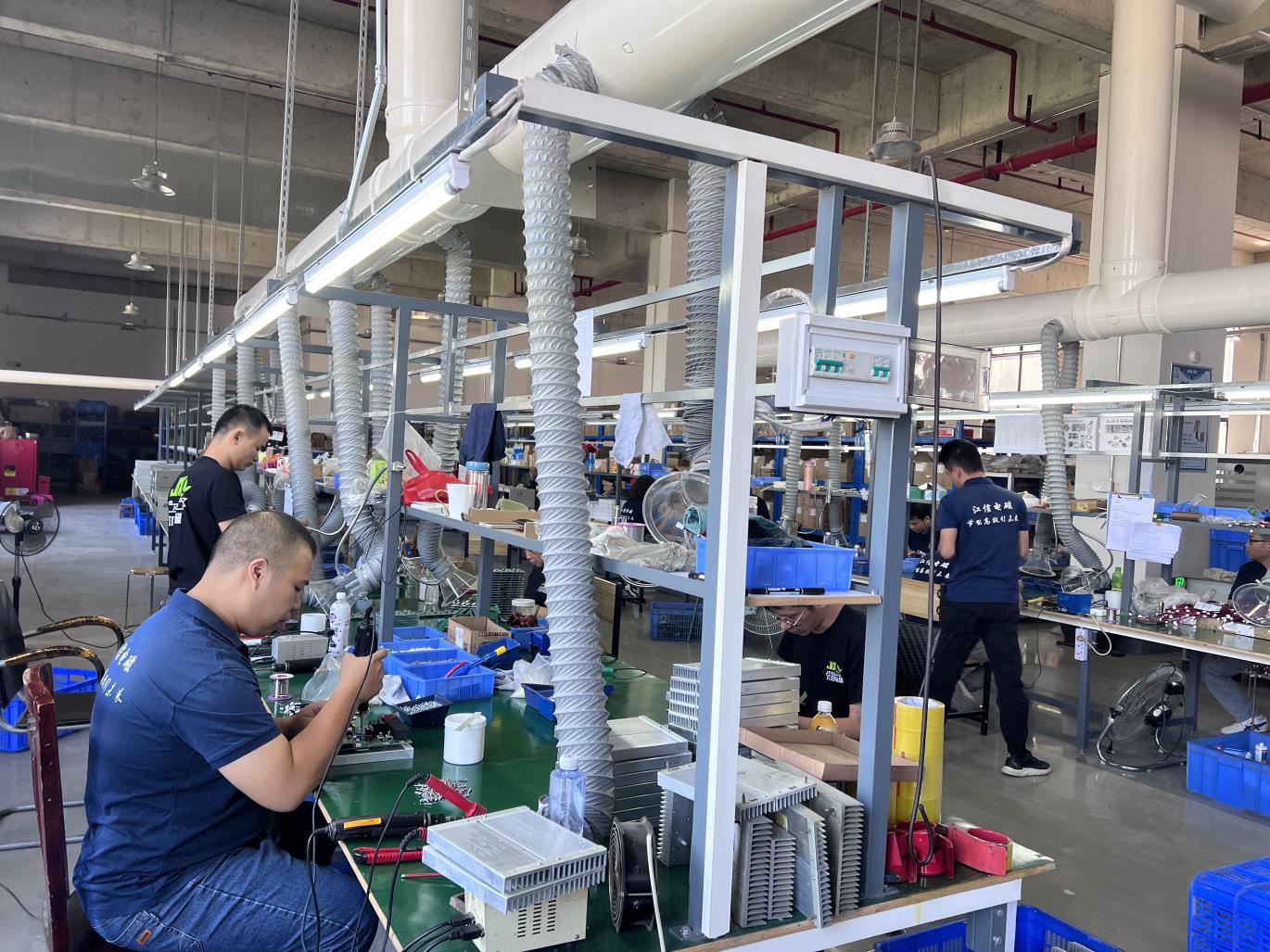
Assembly of induction heating equipment: the control board, resonant capacitor bank and coil terminations are matched as a set before testing.
Comparison Table: Reading the Specifications Side by Side
The tables below translate board-level specifications into what they change at the machine level, and compare the two bridge topologies used in industrial induction heating control boards.
| Specification | Value on the JS1300-10/15 | What it means in practice |
|---|---|---|
| Input and rating | Single-phase full-bridge, 8 kW, 220 V / 50 Hz | Direct fit for single-phase industrial supplies in the 8 kW class; no three-phase feed required |
| Frequency control | DSP-based high-speed automatic phase-locking | Drive stays at resonance as the coil heats and the load changes; no manual re-tuning at commissioning |
| Power regulation | 20%–100% stepless | Continuous turn-down instead of on/off switching; supports ramp and soak profiles |
| Control interface | 0–5 V PID adjustment | Direct connection to a host PLC or temperature controller; loop behaviour set by tuning |
| Temperature input | ±1 °C load temperature detection accuracy | Fine measurement resolution for the control loop; final process band also depends on sensor placement |
| Start-up | Fully electrically isolated soft start, start time under 1 second | No inrush at power-up; fast restart between batches |
| Fault protection | ≤2 µS instantaneous overcurrent protection | Interruption inside the fault timescale, before device damage develops |
| Attribute | Half-bridge series resonant | Full-bridge series resonant |
|---|---|---|
| Switch count | Two devices | Four devices |
| Voltage across each device | Approximately half the DC bus | The full DC bus |
| Power delivered at the same bus voltage and tank | Lower | Substantially higher |
| Typical fit | Compact, lower-power units | Single-phase 8 kW class and higher, such as the JS1300-10/15 |
| Design attention required | Split-capacitor balancing | Dead time and shoot-through control on both legs |
One comparison deserves context rather than a table cell. JONSON reports that induction heating systems built around this platform reach a thermal efficiency of 95%–98%, with comprehensive energy savings of 30%–70% compared with traditional induction heater machines, an expected lifespan three times longer and maintenance requirements 90% lower. Those figures describe the platform, not the board in isolation, but they explain why buyers treat control quality as a cost question rather than a technical curiosity.
Frequently Asked Questions
Does an induction heater control board have to meet IEC 60519-1 and IEC 60519-3?
Industrial induction heating equipment must comply with IEC 60519-1, which covers general requirements for electroheating installations, and IEC 60519-3, which sets particular requirements for induction heating and melting. The control board is part of that installation, so its isolation, soft-start behaviour, overcurrent protection and fault response are assessed as part of the finished machine rather than as a stand-alone component. Buyers should check the declaration against the machine configuration actually being delivered, including the coil and any custom integration.
Can the JS1300-10/15 board drive a coil other than the original one?
Within its validated load range the board tracks the resonant frequency automatically, so a change of coil geometry is handled by the phase-locking loop rather than by manual re-tuning. The operational limits still apply: use only original factory-supplied coil parts, keep the unit away from dust, oil and flammable or explosive materials, and do not alter the internal wiring. A coil outside the validated range is a load-matching question for the supplier, not something the tracking loop is designed to absorb.
What drives the total cost of an induction heating system beyond the board price?
The purchase side is made up of the control board, the matched induction heating coil, the resonant capacitor bank and the integration work around them. The running side is usually larger: energy consumption, maintenance labour and unplanned downtime. JONSON reports thermal efficiency of 95%–98%, comprehensive energy savings of 30%–70% against traditional induction heater machines, an expected lifespan three times longer and 90% less maintenance, which shifts the evaluation toward total cost over service life rather than component price alone.
How should the board be installed and maintained so protection keeps working?
The unit requires ample space for heat dissipation and should be kept away from dust, oil and flammable or explosive materials. Cooling ducts must be cleaned of dust regularly, and only original factory-supplied coil parts should be fitted. Before any repair, disconnect the power and allow the circuit to discharge completely, and do not alter the internal wiring. These conditions are part of the protection design, not optional housekeeping.
How can a buyer validate a control board on a real load before committing to series production?
The practical route is to test the board with the intended coil and the actual load profile, checking phase-locking behaviour across the temperature range, the 20%–100% stepless range at the working setpoint, and the response of the 0–5 V PID loop under the controller that will run the machine. JONSON supplies induction heating control boards and matched coils, and sample or quotation requests can be raised through www.jonson-ih.com or by contacting the team directly at jx@fsjxrn.com.cn.
Conclusion
An induction heater control board is a power-conversion device with a control problem attached: it must hold a moving resonant point, regulate power continuously, follow an external temperature loop and interrupt faults inside the fault timescale. The JS1300-10/15 illustrates what that looks like in specification form, with a single-phase full-bridge 8 kW design at 220 V / 50 Hz, DSP-based high-speed automatic phase-locking, 20%–100% stepless power regulation, 0–5 V PID adjustment, fully electrically isolated soft start, ≤2 µS instantaneous overcurrent protection, a start time under one second and ±1 °C load temperature detection accuracy.
For a buyer at the decision stage, those figures are the ones worth verifying on a real load, because they determine what the induction heating system does after installation rather than what it does on a datasheet. The coil defines where the heat goes; the board defines whether the heat arrives in a controlled, repeatable and protected way.

Control board, resonant capacitor and coil are assembled and matched as a system before dispatch.
Evaluate the control board against your own load profile
JONSON (Guangdong Jiangxin Electronic Technology Co., Ltd.) supplies induction heating control boards, matched induction heating coils and complete induction heating systems for industrial projects. Share your power rating, supply voltage, coil geometry and temperature profile, and the team will confirm whether the JS1300-10/15 configuration fits your application.
Website: www.jonson-ih.com | Email: jx@fsjxrn.com.cn | Tel / WhatsApp: +86 18664277928
Have Questions or Need More Details?
Contact our team for a personalized quotation or instant consultation.
Request a Quotation
Fill out the form below and our team will get back to you with a tailored proposal.
WhatsApp Direct Chat
Prefer to chat in real-time? Message us on WhatsApp for instant assistance & quick answers.
- Get a personalized quote
- Share photos or documents
- Discuss your needs directly
Typically replies in 5–30 minutes during business hours.