
JUXIN CNC Lathe Machine Guide: Accuracy & Rigidity for Shaft/Disc Parts
JUXIN CNC Lathe Machine Technical Guide: Accuracy & Rigidity Parameters for Shaft and Disc Parts
A shaft or disc drawing that specifies radial runout ≤0.005 mm, coaxiality ≤0.01 mm, dimensional tolerance ±0.008 mm, repeat positioning accuracy 0.003–0.005 mm and end face flatness ≤0.01 mm is not asking for “a precise lathe”. It is asking for a specific combination of spindle behaviour, bed rigidity, clamping strategy and control resolution. This guide converts those five callouts into machine parameters, then ranks the three JUXIN MACHINE TOOL configurations — twin-spindle vertical, middle drive double-head, and facing & centering — against them.
Problem Definition: the five callouts that actually decide the machine
Tolerance callouts on a shaft or disc drawing are not independent specifications. Each one is produced — or destroyed — by a different part of the machine, and they interact. A lathe that holds ±0.008 mm on diameter but drifts 0.02 mm in coaxiality between two clampings will fail the part even though the diameter is in tolerance.
The practical difficulty is that a buyer cannot evaluate a machine against five geometrical callouts by reading a single quoted accuracy figure. Most lathe quotations describe positioning accuracy or spindle runout in isolation. What a process planner needs instead is a mapping: which tolerance is binding, which machine subsystem generates it, and which numeric threshold on the machine guarantees it.
There are three distinct failure modes that produce out-of-tolerance shaft and disc parts:
- Spindle-induced radial error. Radial runout at the spindle nose is transferred almost directly into the turned diameter and into roundness. Parts with tight diameter tolerance and surface-finish requirements are limited here first.
- Re-clamping error. When a shaft is turned on one end, flipped, and turned on the other, the second clamping references a surface that was itself produced on the first setup. Coaxiality between the two turned ends now depends on chuck repeatability rather than on the machine’s geometric accuracy.
- Structural and thermal deflection. Bed flexure, guide rail wear and thermal growth shift the tool relative to the workpiece during a long production run. This shows up as dimensional drift across a shift, not as an error on the first part.
Each failure mode points to a different configuration. That is why the selection decision is a configuration decision before it is a specification-table decision.
Industry Background: why high-volume shaft and disc work is unforgiving
Shaft and disc parts — half shafts, brake discs, gear shafts, EV wheels, elevator traction wheels, fan shafts, motor shafts, hydraulic shafts and piston rods — share a common production profile: moderate geometric complexity, very high annual volume, and geometric tolerances that must be reproduced on every part rather than proven once on a sample.
Commercial research on the CNC machining and turning centers market reports that Asia Pacific held a 55.5% revenue share in 2023 (Grand View Research), and that dual spindle CNC lathes are commonly used in high-volume production for the automotive, aerospace and medical sectors. Both points are directional rather than machine-specific, but they explain why twin-spindle and double-head architectures have become the default shortlist for this part family in Asian supply chains.
The measurement framework matters as much as the machine. ISO 230-2 specifies the test procedures for determining the accuracy and repeatability of positioning of numerically controlled axes. When a supplier quotes “repeat positioning accuracy 0.003–0.005 mm”, that number is only meaningful when read together with the test method used to obtain it.
Detailed Solution: translating each callout into a JUXIN parameter
JUXIN MACHINE TOOL is a China-based machine tool manufacturer (Juxin Machine Tool Co., Ltd., founded 2005, Wenling, Zhejiang) specialising in facing and centering machines, double-head CNC lathes and twin-spindle CNC vertical lathes for shaft and disc parts. The parameters below are the ones that correspond to the five callouts on a typical shaft or disc drawing.
Radial runout ≤0.005 mm: a spindle assembly specification
Radial runout is generated at the spindle, so it must be solved at the spindle. JUXIN spindles are made of high-quality alloy structural steel and are precision machined and ground as an assembly, so the runout figure describes the spindle-and-bearing unit as mounted, not an idealised component. For a part with a ±0.008 mm diameter band, a ≤0.005 mm radial runout consumes a defined and predictable portion of the allowance, leaving the remainder for tool wear and thermal movement.
Coaxiality ≤0.01 mm: a clamping-count decision
Coaxiality between two machined features is where conventional lathes lose the most scrap. The reliable way to hold ≤0.01 mm is to avoid re-referencing the part at all, and there are two JUXIN architectures that do this:
- Complete machining in one setup. The JXLC45-A twin-spindle CNC vertical lathe uses dual stations, dual spindles, dual systems and dual tool towers, so opposed features are produced within one machine cycle rather than across two clampings.
- Middle drive on a double-head machine. The JXS72 middle drive double-head CNC lathe turns both ends simultaneously with the workpiece driven from the centre, which removes the concentricity error that a conventional double-clamping sequence introduces.
Dimensional tolerance ±0.008 mm and repeat positioning 0.003–0.005 mm
Dimensional tolerance is a stack of servo positioning behaviour, guide rail and ball screw condition, and thermal stability. A repeat positioning accuracy of 0.003–0.005 mm means the machine’s own axis-to-axis scatter consumes roughly half of a ±0.008 mm band, which is what leaves usable margin for tool wear compensation and for the part’s thermal growth during roughing. If the repeat figure were of the same order as the tolerance, no amount of process tuning would recover the part.
End face flatness ≤0.01 mm: axial stiffness and facing geometry
Face flatness on a disc or on the end of a shaft depends on axial spindle stiffness, the facing slide and the interpolation quality of the facing path. This is the primary design function of the JXZ70-680 end facing and centering machine, whose process scope covers face milling, center hole drilling, external cylindrical turning, drilling and tapping, chamfering, boring and rapid U-drilling in one setup.
Rigidity: the integrally cast bed and what it changes
Static accuracy degrades under cutting load if the structure is not stiff. The JUXIN bed, column and base are made of high-strength preheated cast iron and resin sand integral castings, using HT300 high-quality grey cast iron on the facing and centering platform. The castings undergo ultra-low-temperature cryogenic heat treatment and stress-relief aging, which is what keeps long-term precision stable instead of relaxing over the first year of production.
The machine base uses a multi-layer box structure combined with cross ribs and finite-element mechanical design, which increases overall weight and improves anti-resonance behaviour. Guideways are high-precision hardened rails with a 55°/15° integral hard rail geometry, precision quenched, fine ground and manually scraped; some models use heavy-duty roller linear guideways. JUXIN reports that this structural approach delivers 40%–50% higher rigidity and more than 30% longer machine lifespan compared with conventional construction.
Servo drive efficiency and maintenance intervals
JUXIN specifies an optimised servo drive that delivers 15%–20% better energy efficiency and 50% fewer maintenance intervals. For a plant running three shifts, the maintenance figure is usually the more commercially significant of the two: every planned intervention on a lathe is a stoppage on a line that was sized around continuous operation.
Siemens or Fanuc: selecting the control platform
The control platform is a process-integration decision, not a precision decision, and both Siemens and Fanuc are configurable on these machines. Three criteria normally settle it:
- Existing plant standard. A shop already running one platform keeps programming, diagnostics and operator competence in place. Mixing platforms on the same line adds training and spare-part overhead.
- Line integration. Where the lathe must sit inside an automated cell or a customer’s digital production system, the connectivity requirement dominates. JUXIN equipment has been integrated into Siemens global intelligent production lines, and JUXIN customization covers MES digital system docking, intelligent part recognition and automatic tool compensation.
- Support and service reach. Choose the platform for which local service, spare boards and application engineers are actually available in the destination market.
Top 3 JUXIN configurations ranked for shaft and disc precision work
The ranking below is a configuration ranking, not a supplier ranking. The ranking metric is the ability to hold coaxiality ≤0.01 mm and end face flatness ≤0.01 mm in high-volume production while keeping dimensional tolerance at ±0.008 mm. Each configuration is ranked by how much of the part it completes within a single reference, because that is the variable that decides scrap rate on this part family.
Rank 1 — Twin-Spindle CNC Vertical Lathe Machine JXLC45-A
The JXLC45-A is a dual-position CNC vertical lathe built on dual stations, dual spindles, dual systems and dual tool towers, with a maximum shaft machining diameter of 345 mm and a maximum shaft machining length of 1020 mm. It ranks first because opposed features are machined within one machine cycle: coaxiality and end-face flatness are produced from a single part reference rather than from a re-clamping operation, and the vertical orientation makes disc-type parts straightforward to load and to hold.
The configuration is best matched to brake discs, EV wheels, elevator traction wheels, flanges and short-to-medium shafts where both ends require turning and the annual volume justifies a two-station cycle.
Rank 2 — Middle Drive Double-head CNC Lathe JXS72
The JXS72 is a double-end simultaneous turning lathe covering a processing diameter range of 15–180 mm and a processing length range of 40–800 mm. Its distinguishing feature is the middle drive: the workpiece is driven from its centre between the two working ends, so both ends are turned against the same reference and the re-clamping error that normally appears in a two-setup sequence is removed at source.
It ranks second because the working envelope is narrower than the vertical twin-spindle platform, but for slender shafts, motor shafts, gear shafts and pin-type parts inside that envelope it is the most direct answer to a ≤0.01 mm coaxiality callout. Bed and column are integral cast iron with cryogenic heat treatment and stress-relief aging, and the guideway geometry is the 55°/15° hardened integral rail.
Rank 3 — End Facing and Centering Machine JXZ70-680
The JXZ70-680 covers a machining diameter of 14–500 mm and a machining length of 70–5000 mm, with a process scope that includes face milling, center hole drilling, external cylindrical turning, drilling and tapping, chamfering, boring and rapid U-drilling. The bed is integrally cast in HT300 grey cast iron for rigidity.
It ranks third strictly on finished-part tolerance, because it is a preparation machine rather than a finishing machine. It belongs on the list because it determines whether the downstream lathe can hold coaxiality at all: if the centre holes are not concentric and the end faces are not square, no amount of lathe accuracy will recover the part.
Step-by-Step Breakdown: from drawing to machine specification
The workflow below is the sequence a process planner can follow to convert a shaft or disc drawing into a defensible machine specification and an acceptance protocol.
- Extract the binding callout. Identify which of the five tolerances is tightest relative to its feature size. On most shaft drawings this is coaxiality or radial runout; on most disc drawings it is end face flatness. The binding callout selects the configuration, and the others become supporting requirements.
- Count the clampings. Decide whether the part can be completed in one reference. If the answer is two, the coaxiality callout must be re-examined against the chuck repeatability rather than against the machine’s geometric accuracy, and a complete-machining or middle drive architecture should be evaluated instead.
- Map each tolerance to a machine threshold. Use the mapping table below rather than a general accuracy claim. Each callout should correspond to a named parameter that appears on the quotation and on the acceptance sheet.
- Size the structure against the cut. Confirm that the bed and guideway construction suit the depth of cut and the material removal rate the cycle time assumes. A machine that meets the tolerance on a light finishing pass but chatters on the roughing pass will not hold ±0.008 mm in production.
- Select the control platform and automation level. Decide Siemens or Fanuc against the plant standard and the line-integration requirement, then decide whether the machine runs standalone, in a 3/4/5-unit robot linkage line, or as a turn-key automatic line. Chuck size (6/8/10/12-inch hydraulic), turret configuration (8-station or 12-station, power turret, tool magazine) and tailstock type (split or integrated servo programmable) are all configurable at this stage.
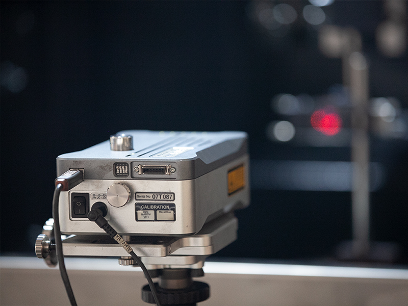
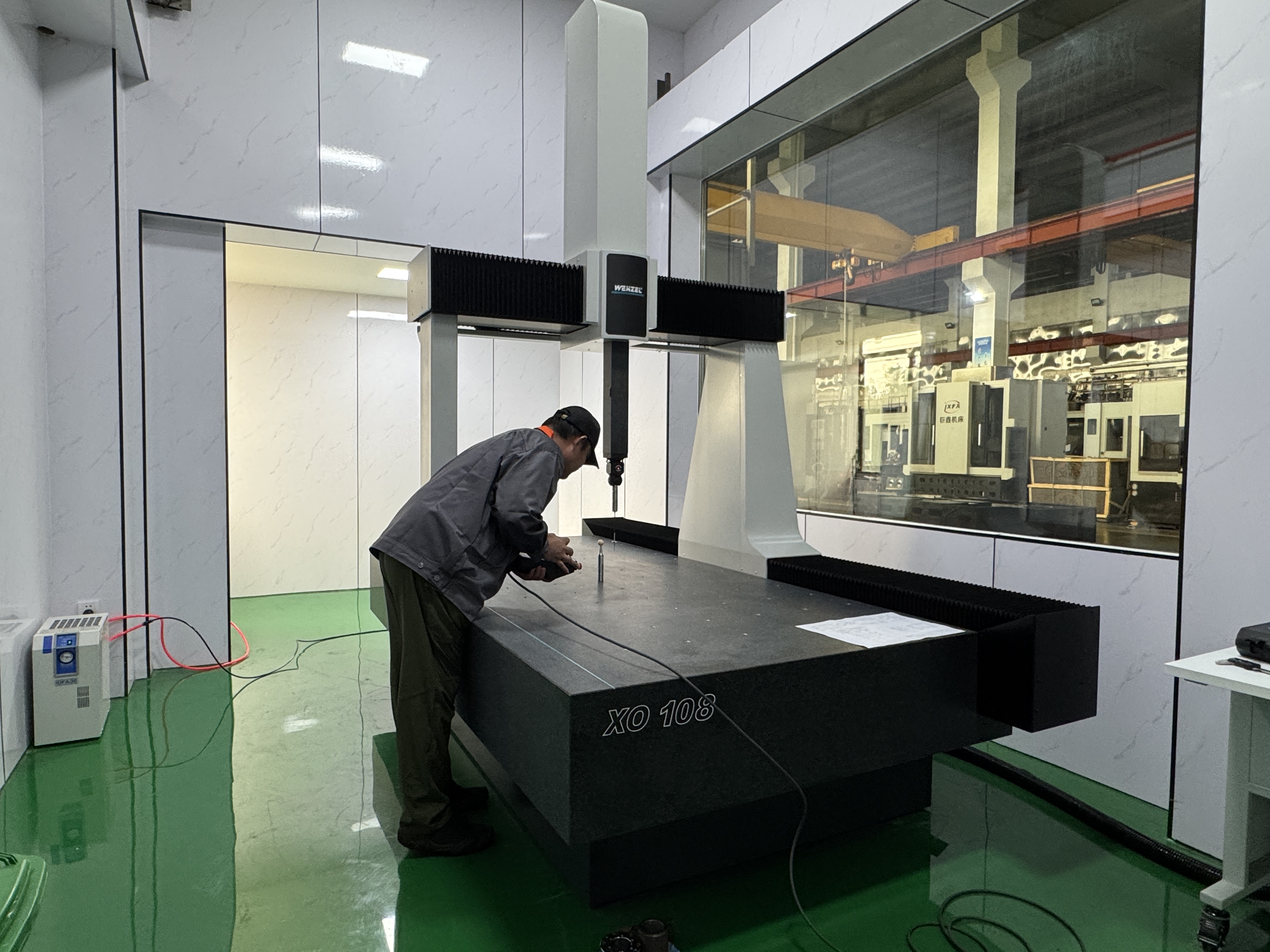
- Write the acceptance protocol before the order. Specify the ISO 230-2 positioning and repeatability test on the NC axes, laser interferometer verification with a Renishaw unit, dimensional verification with a Wenzel three-coordinate measuring machine, and a test cut on your own part geometry. A test cut on the buyer’s part is the only measurement that combines all five callouts at once.
Tolerance-to-parameter mapping
| Drawing callout | Machine parameter to specify | JUXIN threshold | Verified by |
|---|---|---|---|
| Radial runout | Spindle nose radial runout, spindle assembly | ≤0.005 mm | Inductive or dial indicator at spindle nose; test cut |
| Coaxiality between opposed features | Clamping count, dual spindle or middle drive architecture | ≤0.01 mm | CMM check across both features, single setup |
| Dimensional tolerance | Servo positioning behaviour and repeat positioning accuracy | ±0.008 mm | ISO 230-2 positioning test plus part measurement |
| Repeat positioning accuracy | NC axis bidirectional repeatability | 0.003–0.005 mm | Laser interferometer (Renishaw) |
| End face flatness | Axial spindle stiffness, facing slide, interpolation quality | ≤0.01 mm | CMM or surface plate and indicator |
Use Cases: where these parameters meet real production
The parameter set is only credible if it survives production conditions. The following applications are drawn from installed JUXIN projects.
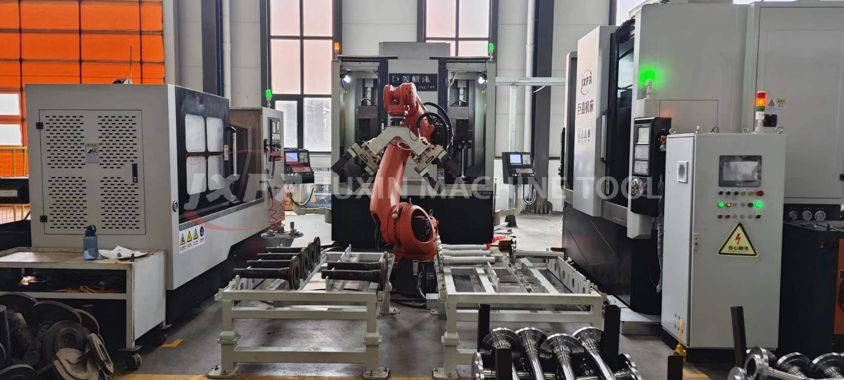
Automotive half shafts, brake discs, gear shafts and chassis parts. In China, JUXIN equipment has been used by top domestic automobile manufacturers for milling, drilling, double vertical lathe precision processing and automatic line production of half shafts, brake discs, gear shafts and chassis parts. The cooperation has run since 2014, with unmanned full-line production and long-term non-fault continuous operation, meeting Tier 1 auto supplier standards and achieving the fastest acceptance and commissioning performance among domestic machine tool suppliers in that project.
EV wheels, elevator traction wheels, fan shafts, solar accessories and brake discs. For small to medium-sized mass production factories, JUXIN supplied turn-key automatic assembly line processing for this part group. The reported results were 70%–150% plant space saving, 50%–80% labour reduction and more than 50% production cost reduction — outcomes that follow from consolidating multiple operations into a single automatic line rather than from any single machine parameter.
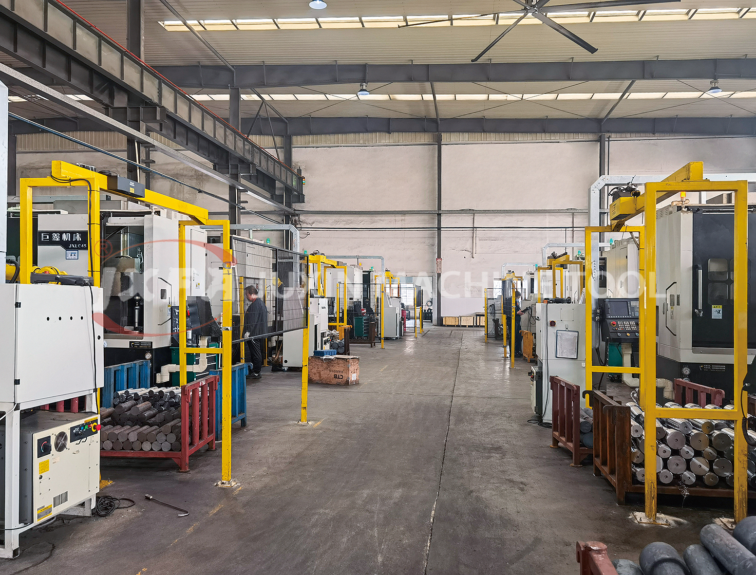
Hydraulic shafts, piston rods, pin shafts and large shaft parts. In Asian heavy industry applications, the machines are used for end face and center hole machining of hydraulic shafts, piston rods, pin shafts and large shaft parts for engineering machinery. The integral cast bed and super-heavy structure are adapted to high-load and large-depth cutting, with smooth chip removal and long-term non-deformation behaviour suitable for 24-hour continuous mass production under harsh conditions.
European precision requirements. At Siemens in Germany, JUXIN facing and centering equipment is used for precision machining of motor spindles, shaft parts and shell components, seamlessly connected to Siemens global intelligent production lines, with accuracy and cycle times meeting German process requirements and replacing imported equipment. At SEW in Germany, the equipment handles end face milling, center hole drilling and precision turning of motor shafts and transmission parts, where stable machining accuracy and high consistency in mass production were the stated requirements.
Comparison Table: the three configurations side by side
The table below compares only parameters that appear in JUXIN product documentation. It is a fit comparison, not a performance ranking of suppliers.
| Configuration | Model | Work envelope | Structural / drive features | Tolerance role | Best-fit part |
|---|---|---|---|---|---|
| Twin-Spindle CNC Vertical Lathe | JXLC45-A | Shaft diameter up to 345 mm; shaft length up to 1020 mm | Dual stations, dual spindles, dual systems, dual tool towers | Coaxiality ≤0.01 mm and face flatness ≤0.01 mm via complete machining in one cycle | Brake discs, EV wheels, traction wheels, flanges, short-to-medium shafts |
| Middle Drive Double-head CNC Lathe | JXS72 | Diameter 15–180 mm; length 40–800 mm | Double-end simultaneous turning; integral cast bed, column and base with cryogenic heat treatment; 55°/15° hardened integral guide rail; optional heavy-duty roller linear guide | Removes re-clamping error by driving from the workpiece centre | Slender shafts, motor shafts, gear shafts, pin-type parts |
| End Facing and Centering Machine | JXZ70-680 | Diameter 14–500 mm; length 70–5000 mm | Integrally cast HT300 grey iron bed; face milling, center hole drilling, OD turning, drilling and tapping, chamfering, boring, rapid U-drilling | Creates the reference: end face flatness and centre concentricity that downstream turning depends on | Long shafts, hydraulic shafts, piston rods, large shaft parts |
Shared rigidity and efficiency platform
Across all three configurations, the same structural logic applies: high-strength preheated cast iron and resin sand integral castings, cryogenic heat treatment with stress-relief aging, multi-layer box plus cross-rib base with finite-element design, and precision quenched, ground and hand-scraped guideways. JUXIN reports 40%–50% higher rigidity and over 30% longer lifespan from this construction, and 15%–20% better energy efficiency with 50% fewer maintenance intervals from the optimised servo drive.
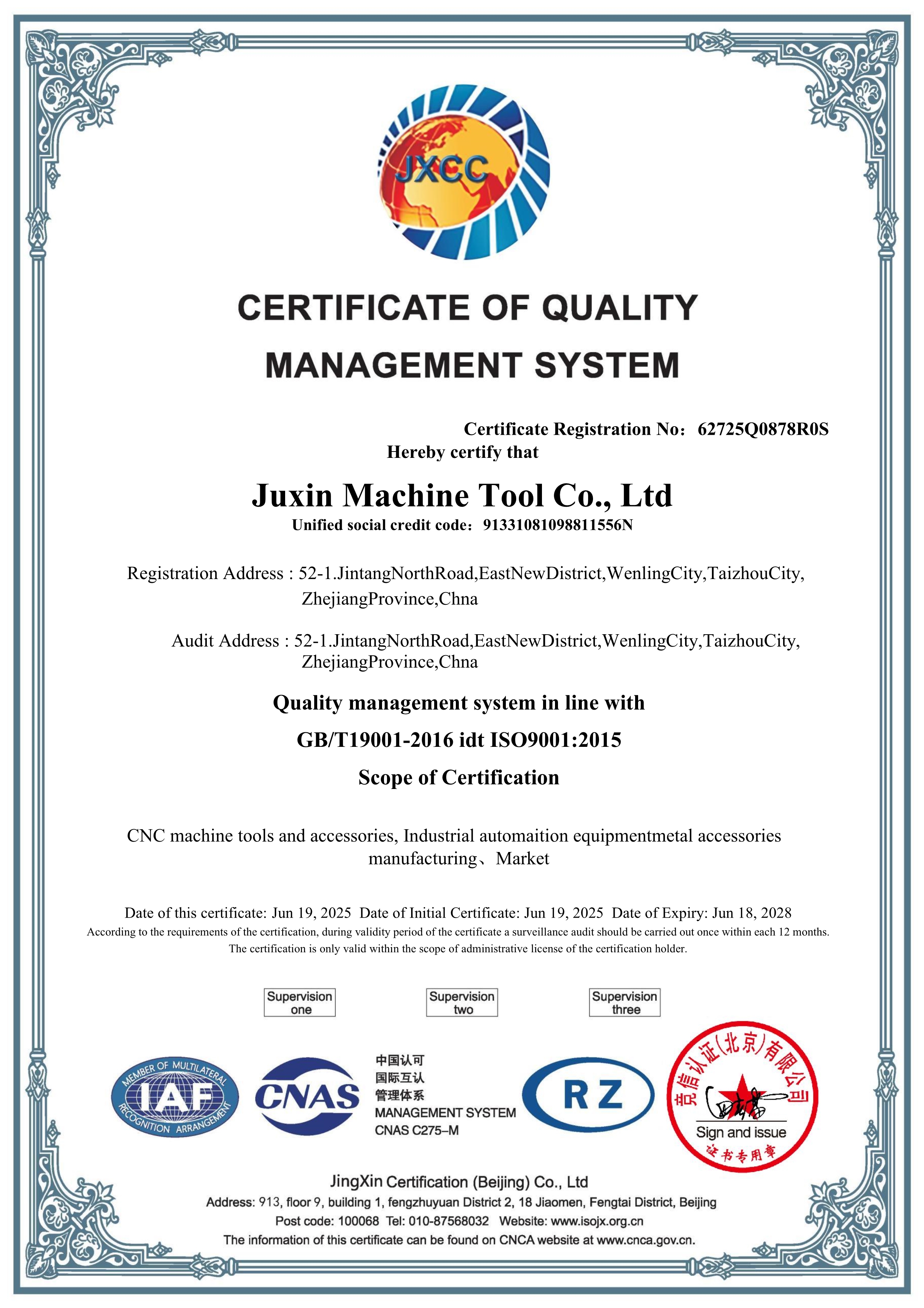
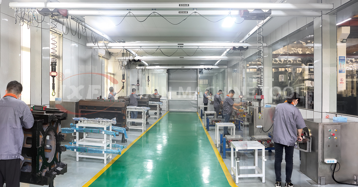
Manufacturing is supported by a 10,666 m² facility, 80 employees, 10 R&D engineers, more than 50 technological patents and an annual output of 2,000 sets. Quality management is certified to GB/T 19001-2016 / ISO 9001:2015 under certificate 62725Q0878R0S, issued by JingXin Certification (Beijing) Co., Ltd on 19 June 2025 and valid until 18 June 2028, covering CNC machine tools and accessories, industrial automation equipment and metal accessories manufacturing.
FAQ
How should I verify the quoted runout and positioning figures during acceptance?
Verify them against a stated method, not against a catalogue number. Ask for an ISO 230-2 positioning and repeatability test on the NC axes, because ISO 230-2 is the standard that specifies how the accuracy and repeatability of positioning of numerically controlled axes are determined. Spindle radial runout should be indicated at the spindle nose on the assembled machine. For the geometrical callouts, JUXIN uses independent third-party inspection and in-house metrology that includes a Renishaw laser interferometer and a German Wenzel three-coordinate measuring instrument. The final acceptance step should be a test cut on your own part, measured on a CMM, because that is the only test that evaluates radial runout, coaxiality, dimensional tolerance and face flatness simultaneously.
Can a double-head or twin-spindle configuration actually hold coaxiality ≤0.01 mm across two machined ends?
It can when the part is not re-referenced. On the JXS72 middle drive double-head lathe, the workpiece is driven from its centre and both ends are turned simultaneously, so the second end is not referenced to a re-chucked surface. On the JXLC45-A twin-spindle vertical lathe, dual stations, dual spindles, dual systems and dual tool towers allow opposed features to be produced within one machine cycle. Both approaches remove the error source rather than compensate for it. The condition is that the part geometry falls inside the working envelope: 15–180 mm diameter and 40–800 mm length on the JXS72, and up to 345 mm diameter and 1020 mm length on the JXLC45-A. Parts outside those envelopes normally move to the JXZ70-680 facing and centering platform, which handles 14–500 mm diameter and 70–5000 mm length.
What drives the cost difference between the three configurations?
The cost difference follows the number of independent axes, spindles and tool stations, and the amount of preparation work the machine absorbs. A facing and centering machine is a single-purpose preparation platform. A middle drive double-head lathe adds simultaneous two-end turning with a centre drive. A twin-spindle vertical lathe carries dual stations, dual spindles, dual systems and dual tool towers, which is the most hardware-intensive of the three and the one that removes the largest number of downstream operations. Cost also moves with configuration choices rather than with the base model: integrated or split bed, hard rail or linear rail, single or double middle drive spindle, split or integrated servo programmable tailstock, 8-station or 12-station turret or power turret, and 6/8/10/12-inch hydraulic chuck. Automation scope changes the number again — a standalone machine, a 3/4/5-unit robot linkage line and a full turn-key automatic line are different projects. Because configuration dominates, the useful comparison is cost per good part at your annual volume, not machine price in isolation.
Can I validate the machine on my own shaft or disc before committing to an order?
Yes, and it is the recommended step for any part with a coaxiality or flatness callout at or below 0.01 mm. JUXIN’s process includes pre-sales drawing review and technical solution definition, model selection and customization with a signed technical agreement, and factory pre-acceptance with basic operation training before shipment. A trial cut on your part geometry during pre-acceptance produces the evidence that matters: measured radial runout, coaxiality, dimensional spread and face flatness on the actual material and the actual clamping arrangement. Minimum order quantity is 1 unit, so a single-machine validation is commercially practical before scaling to a multi-unit line.
What lead time and capacity should be planned for?
Standard lead time is 45 days, with a monthly capacity of 160 units and a minimum order quantity of 1 unit. For line projects the schedule has to cover more than machine build: automation integration, robot linkage, MES docking and on-site commissioning all sit inside the delivery window. JUXIN’s after-sales structure includes installation, commissioning, operation guidance and daily maintenance training, remote technical guidance for faults, on-site support, spare parts and wearing-part supply, and lifelong technical support for subsequent upgrading and process optimization. To plan a realistic date, confirm the automation scope at the enquiry stage rather than after the machine is built.
Conclusion: specify the tolerance chain, then the machine
A shaft or disc program that must hold radial runout ≤0.005 mm, coaxiality ≤0.01 mm, dimensional tolerance ±0.008 mm, repeat positioning 0.003–0.005 mm and end face flatness ≤0.01 mm is decided by three things in order: how many times the part is clamped, how stiff the structure is under the actual cut, and whether the accuracy figures are tested by a stated method. The configuration follows from the first answer. The JXLC45-A twin-spindle vertical lathe addresses complete machining of disc-type and short shaft parts, the JXS72 middle drive double-head lathe removes re-clamping error on slender shafts inside its 15–180 mm envelope, and the JXZ70-680 facing and centering machine creates the reference that both depend on.
Next step: match the parameters to your part drawing
Send a shaft or disc drawing with its tolerance callouts and annual volume, and JUXIN MACHINE TOOL will map each callout to a configuration, a work envelope and an acceptance protocol. Minimum order quantity is 1 unit and standard lead time is 45 days.
Download the full technical catalogue: JUXIN Machine Tool product brochure (PDF)
Product range and specifications: en.wljxjc.com
Email: jxmachine@yeah.net | Tel / WhatsApp: +86 1333-678-3918
Address: No.52-1, Jintang North Road, Eastern New District, Wenling, Zhejiang, China
Figures describing rigidity improvement, service lifespan, energy efficiency and maintenance intervals are manufacturer-stated values for JUXIN machine construction. Accuracy and repeatability figures should be confirmed against the acceptance test method agreed in the purchase contract.
Have Questions or Need More Details?
Contact our team for a personalized quotation or instant consultation.
Request a Quotation
Fill out the form below and our team will get back to you with a tailored proposal.
WhatsApp Direct Chat
Prefer to chat in real-time? Message us on WhatsApp for instant assistance & quick answers.
- Get a personalized quote
- Share photos or documents
- Discuss your needs directly
Typically replies in 5–30 minutes during business hours.