
Precision Shaft Machining: How Double-Head Lathes Streamline High-Volume Production
A middle-drive double-head CNC lathe machines both ends of a shaft in one clamping. That single change removes the workpiece turnaround, the second fixture and the second setup alignment that generate most of the concentricity error in high-volume shaft work. On the JXS72 platform built by JUXIN MACHINE TOOL, the method covers shafts from 15 mm to 180 mm in diameter and 40 mm to 800 mm in length, and it is the configuration most often specified when a plant has to hold a coaxiality band of ±0.005–0.01 mm at production rates rather than at sample rates.
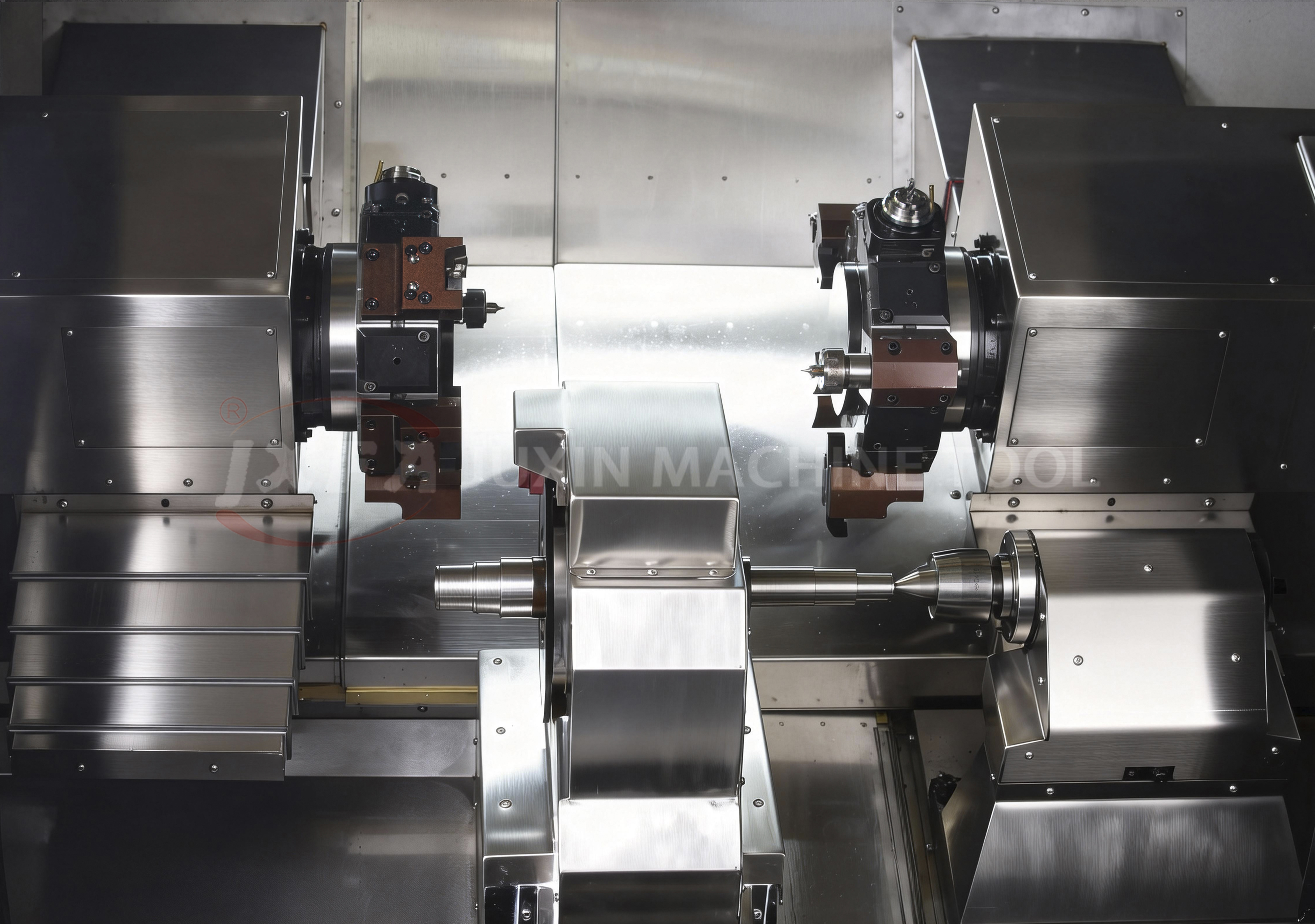
Middle-drive double-head CNC lathe for shaft machining — both shaft ends completed in a single clamping.
Why Precision Shaft Machining Breaks Down at Volume
A shaft is only as good as the relationship between its two ends. Coaxiality between the two journals, depth consistency of the two center holes, and flatness of both end faces decide whether the part can be ground, balanced, assembled and run without vibration. In production, these three characteristics are usually the first to drift — and the cause is nearly always the same: the part is machined in two setups.
In a conventional two-setup flow, the shaft is faced and centered, turned on one end, released, turned around and re-clamped for the second end. Each of those steps adds error of its own: fixture-to-fixture variation, residual clamping stress released after unclamping, nicks and burrs from handling between operations, and thermal drift between the first and second operation. Individually, none of these errors is large. Together they decide whether a shop can hold a ±0.005–0.01 mm coaxiality band across a full production shift instead of only on the first piece.
The preparation stage carries the same risk. The JUXIN end facing and centering platform specifies repeat positioning accuracy of 0.008–0.012 mm, length and center hole depth consistency at both ends of ±0.05 mm (customizable to ±0.02 mm), and center hole surface roughness of Ra1.6–Ra1.8. Those values define what the end-face operation must deliver before turning even starts. If a second setup re-introduces error after the center holes are already established, the accuracy built at the facing station is thrown away.
Industry Background: Shaft and Disc Volumes Keep Rising
The demand pressure behind double-end turning is structural, not seasonal. The global CNC machine market was valued at USD 73.5 billion in 2024 and is forecast to reach USD 187.2 billion by 2034. Within that market, the CNC lathe machine segment held the leading position with approximately 30%–32.82% share in 2024, and Asia Pacific accounted for 37% of CNC machine revenue, valued at USD 27.2 billion. The vertical machining center market alone was estimated at USD 42.6 billion in 2024, with Asia Pacific holding a 54.5% share.
Tolerance expectations are tightening at the same time. Modern CNC lathes used for automotive applications — a segment representing roughly 40% of the market — achieve tolerances as tight as ±0.004 mm. Automotive and transmission work is exactly where precision shaft volume concentrates: motor shafts, half shafts, brake discs, gear shafts, brake shafts and CV joints all arrive in batches that reward single-clamping processing and punish second setups.
Three demand shifts push the same way. Electrification adds motor shafts and rotor-related parts with strict runout limits. Elevator traction wheels, fan shafts and solar accessories require concentric turning of both ends at volume. Heavy industry — hydraulic shafts, piston rods and pin shafts — needs large-depth cutting without losing geometry across a 24-hour schedule. Each of these part families is a natural fit for a configuration that finishes both ends before the part leaves the spindle.
The Solution: Single-Clamping Double-End Turning
The middle-drive double-head CNC lathe — the JXS72 from JUXIN MACHINE TOOL, a Chinese manufacturer of specialised CNC machine tools founded in 2005 and operating a 10,666 m² plant in Wenling, Zhejiang — solves the two-setup problem by changing where the part is held. Instead of gripping one end and turning the other, the spindle drives the workpiece from the middle so both ends are machined simultaneously.
One spindle reference instead of two fixtures
On this platform, the machine completes the outer circle, inner hole, thread, end face and center hole at both ends of the shaft in a single clamping. Because the workpiece is never released and never turned around between operations, the precision errors caused by secondary clamping are eliminated rather than compensated for. This is the mechanical reason a ±0.005–0.01 mm coaxiality band becomes repeatable: both ends are generated from the same spindle axis in the same thermal and mechanical state.
The process also collapses the routing. Work that normally moves between a facing and centering machine, a horizontal lathe and a second lathe becomes a single machine cycle, which shortens the physical distance the part travels and removes the WIP that sits between operations.
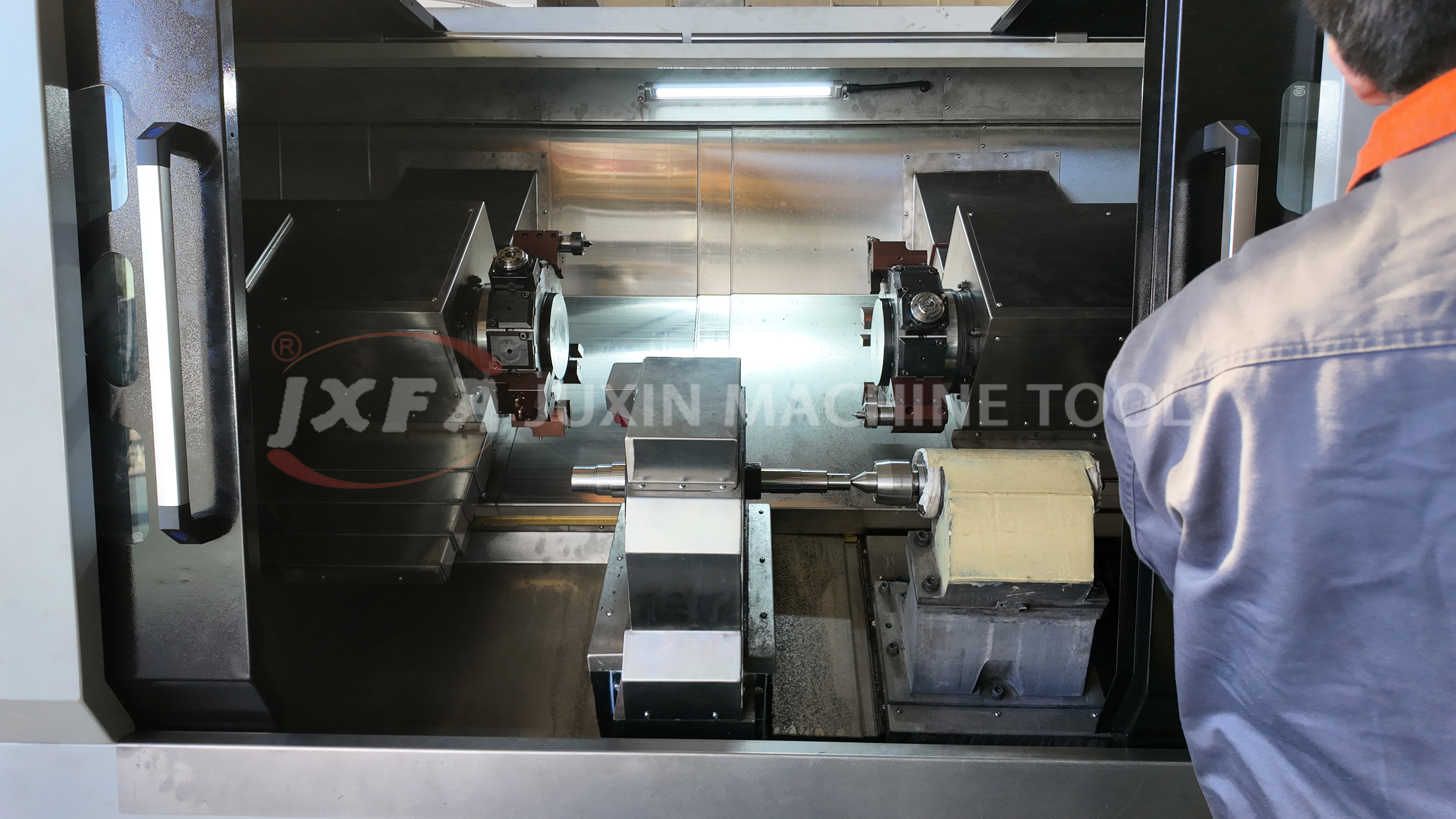
Motor shaft machined on a double-head CNC lathe — both ends turned from one spindle reference.
Machine structure that holds the result
Single-clamping turning only pays off if the structure is rigid enough to keep the axis stable under load. The JXS72 bed, column and base are made of high-strength preheated cast iron using resin sand integral casting, then given ultra-low temperature cryogenic heat treatment and stress-relief aging. The result is high rigidity, resistance to deformation and stable shock absorption, which keeps long-term precision from drifting.
The machine base uses a multi-layer box-type structure combined with cross ribs in a mixed cast-iron design developed with finite element mechanical analysis. This increases overall machine weight and improves both stability and anti-resonance behaviour. The guide rail is a high-precision hardened rail in a 55°/15° integral hard-rail design, with some models equipped with heavy-duty roller linear guide rails; the rail is precision quenched, fine ground and hand-scraped for wear resistance, load capacity and stability in heavy cutting. The spindle is made of high-quality alloy structural steel.
Accuracy and customisation envelope
The published working envelope for the middle-drive double-head platform is a processing diameter range of 15–180 mm and a processing length range of 40–800 mm. Clamping range is customizable from Φ3 to Φ185 mm, and workpiece length can be expanded from 200 to 800 mm. Repeat positioning accuracy is 0.003–0.005 mm, with workpiece roughness of Ra0.8 for non-ferrous metals and Ra1.6 for steel parts.
Configuration flexibility matters because shaft families rarely stay uniform. Buyers can specify single or double middle-drive spindles, extension sleeves and special turret interference-avoidance arrangements. Speed regulation is stepless, with optional servo main motor power, and control systems can be selected from Huazhong, GSK, Syntec or Siemens. Tooling options include gang tool and turret arrangements, and clamping can be pneumatic or hydraulic with automatic clamping and unclamping.
Cycle time and energy per workpiece
Two effects drive the economics. First, both ends are cut in the same cycle, so the second operation disappears entirely. Second, the compact, centralised layout means the part does not travel between machines. In practice, a double-head configuration typically shortens the processing cycle by 40%–60% and reduces energy consumption per workpiece by 20%–30% compared with an ordinary horizontal lathe running the same shaft in two setups.
The wider plant-level numbers from JUXIN turn-key references point the same direction: site space savings of 70%–150%, labour reduction of 50%–80%, and production cost reduction of more than 50% after a line is converted to automated flow.
Operating modes and line integration
The platform runs in several modes so it can start as one machine and later become part of a line:
- Full-automatic single-machine loading, unloading and cyclic program processing.
- Multi-machine robot online mode, automatically skipping tool-change stations for continuous production.
- Fixed-value mass production with fast switching between varieties via stored programs.
- Optional pneumatic or hydraulic clamping with automatic clamping and unclamping.
Matched equipment for a cell includes an articulated robot, loading and unloading platform, conveying assembly line, standard or non-standard hydraulic fixtures, gang tool or turret, and automatic lubrication and chip removal devices.
Working environment and limits
The double-head platform is designed for ordinary machining workshops and batch parts production workshops — it does not require a constant-temperature environment. An inclined-rail full-protection design resists dust and cutting-fluid corrosion, with built-in automatic chip removal. In workshops where cutting fluid and chips are present, full protective sheet metal and centralised chip removal are required.
The limits matter as much as the capabilities. The 15–180 mm diameter and 40–800 mm length envelope suits small-diameter slender shafts and medium-to-small shaft sleeve parts. Larger work moves to a different platform: the twin-spindle CNC vertical lathe for shafts (JXLC45-A) handles shafts up to 345 mm in diameter and 1020 mm in length, while the end facing and centering machine (JXZ70-680) covers diameters of 14–500 mm and lengths of 70–5000 mm. Parts hardened above HRC50 require turning-grinding compound models rather than standard turning configurations.
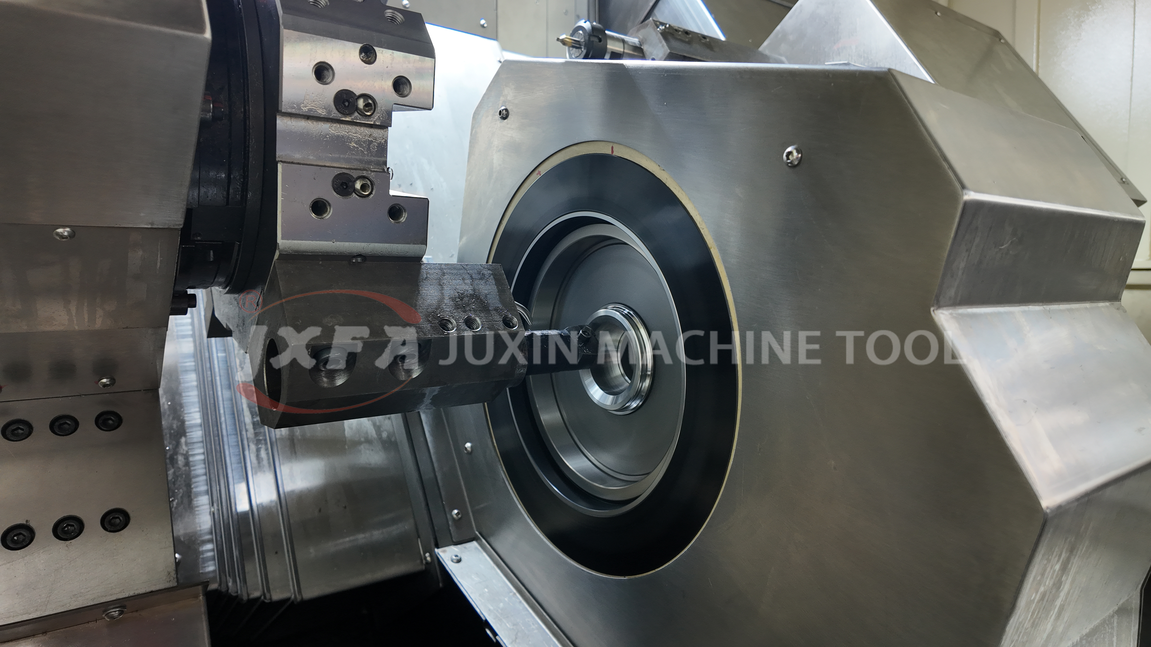
CV joint machined on a double-head CNC lathe — one clamping, both ends referenced to the same axis.
Step-by-Step Breakdown: Building a Double-Head Shaft Cell
Converting a shaft family from two setups to one is a seven-step process. Each step has a decision attached to it that determines whether the accuracy target survives production.
- Qualify the part family against the envelope. Check that shaft diameters fall within 15–180 mm and lengths within 40–800 mm. Parts outside that window should be routed to the twin-spindle vertical lathe (JXLC45-A, up to 345 mm diameter and 1020 mm length) or the facing and centering machine (JXZ70-680, 14–500 mm diameter and 70–5000 mm length).
- Write the accuracy target as a process requirement, not a wish. Define the coaxiality band (for precision shaft work, typically ±0.005–0.01 mm between the two ends), the center-hole depth consistency at both ends, and the required surface roughness — Ra0.8 for non-ferrous metals and Ra1.6 for steel on the double-head platform, Ra1.6–Ra1.8 for center hole surfaces on the facing and centering platform.
- Fix the clamping and drive configuration. Specify clamping range from Φ3 to Φ185 mm and workpiece length from 200 to 800 mm, then select single or double middle-drive spindles and any extension sleeve required by the part geometry.
- Select tooling and turret arrangement. Gang tool or turret, standard or non-standard, with interference-avoidance configuration where the part profile is close to the tool change path.
- Decide the automation level. Start from full-automatic single-machine cyclic processing, then scale to 3-unit, 4-unit or 5-unit robot linkage. Multi-machine online operation lets one robot control two to three production lines and allows automatic skipping of tool-change stations for continuous flow.
- Plan the floor and services. Confirm foundation load-bearing capacity, full protective sheet metal, centralised chip removal, centralised lubrication and cooling. Note that the double-head platform does not require a constant-temperature workshop, which reduces facility cost compared with precision grinding cells.
- Validate before acceptance. JUXIN MACHINE TOOL runs drawing and technical solution review plus model selection before contract signing, factory pre-acceptance and basic operation training during manufacture, and on-site equipment acceptance with operational practical training after delivery. Precision dimensional verification is carried out with independent third-party inspection companies using sampling and full-item performance testing.
- Confirm commercial terms. Minimum order quantity is 1 unit, monthly production capacity is 160 units, and standard lead time is 45 days.
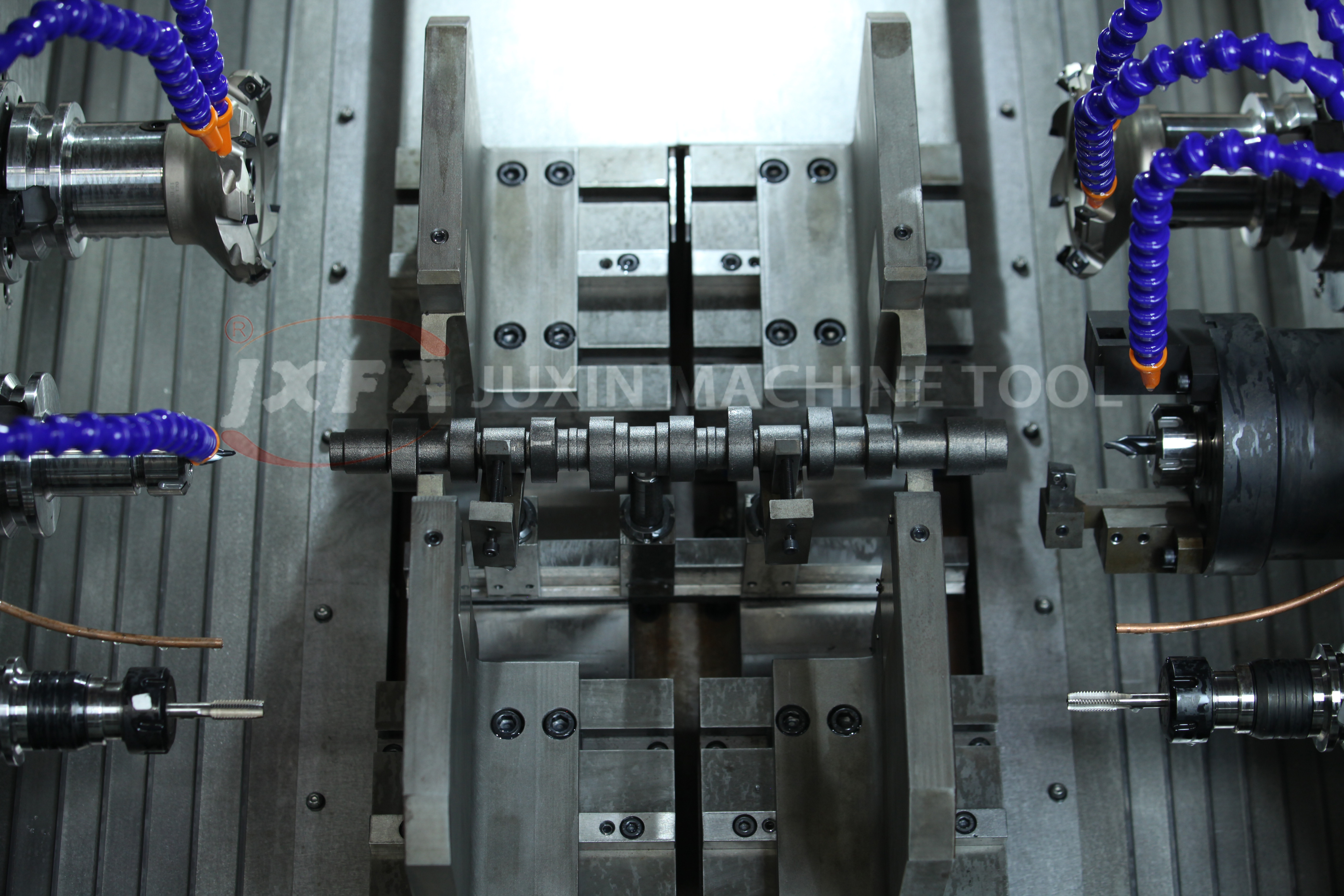
End facing and centering platform — preparing shaft ends to a repeat positioning accuracy of 0.008–0.012 mm before turning.
Use Cases: Where Double-Head Turning Fits Best
The middle-drive double-head platform is specified most often for motor shafts, electric vehicle wheels, elevator traction wheels, fan parts, half shafts, solar energy accessories, brake discs, small shaft sleeve parts, precision pin shafts, hardware fasteners and micro motor parts. These are the part families where small-diameter slender geometry, high batch volume and two-ended accuracy requirements occur together — the reason this application scenario is common in the United States as well as across Germany, Turkey, Vietnam, Thailand, Malaysia, Indonesia, Egypt, Saudi Arabia, Iran, Pakistan, Brazil and Mexico.
Three documented production references show how the configuration behaves in real plants:
- Elevator traction wheel and disc lines. Automatic assembly line processing for EV wheels, elevator traction wheels, half shafts, fan shafts, solar accessories and brake discs delivered plant space savings of 70%–150%, labour reduction of 50%–80% and production cost reduction of more than 50% after turn-key line delivery. The scope ranged from a single machine to multi-machine linkage to full robot automatic production lines.
- Automotive OEM and Tier 1 shaft production. A large vehicle manufacturing group with complete vehicle and component industrial parks machines half shafts, brake discs, gear shafts and chassis parts using milling and drilling, twin-spindle vertical lathe precision processing and automatic line production. Long-term cooperation has run since 2014, with unmanned full-line production and long-term non-fault continuous operation meeting Tier 1 auto supplier standards.
- Heavy industry shaft work. Construction machinery, oilfield equipment and heavy industry producers run end face and center hole machining on hydraulic shafts, piston rods, pin shafts and large shaft parts. Integral cast beds and heavy structure design support high-load, large-depth cutting with smooth chip removal and long-term non-deformation under 24-hour continuous production.
European transmission and electrical manufacturing references include the German industrial groups Siemens and SEW, where JUXIN facing and centering machines handle motor spindles, motor shafts, transmission parts and shell components. Both cases share the same pattern: accuracy and cycle time have to meet European process requirements while the equipment is integrated into existing automated lines.
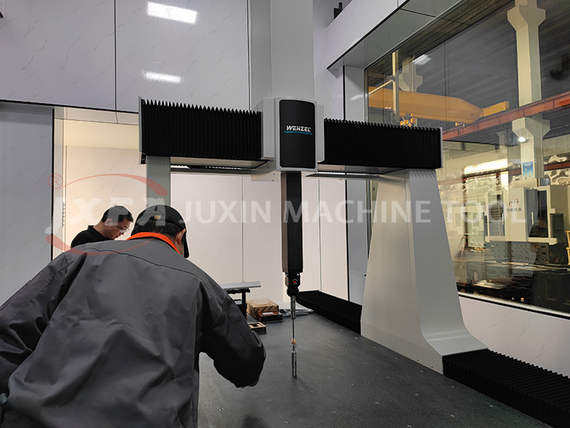
Accuracy verification on a German Wenzel three-coordinate measuring instrument — the check that confirms repeat positioning claims on delivered shaft cells.
Comparison Table: Three JUXIN Shaft-Machining Platforms
The three platforms below are all built by JUXIN MACHINE TOOL and are frequently quoted against the same shaft project. Selecting between them is a geometry and volume decision, not a quality decision.
| Parameter | Middle Drive Double-head CNC Lathe (JXS72) | Twin-Spindle CNC Vertical Lathe for Shafts (JXLC45-A) | End Facing and Centering Machine (JXZ70-680) |
|---|---|---|---|
| Machine type | Double End Simultaneous Turning Lathe | Dual-position CNC vertical lathe machine | CNC milling face end face drilling hole lathe machine |
| Processing diameter | 15–180 mm | Up to 345 mm | 14–500 mm |
| Processing length | 40–800 mm | Up to 1020 mm | 70–5000 mm |
| Core configuration | Middle-drive spindle, single or double drive spindle customizable | Dual stations / dual spindles / dual systems / dual tool towers | HT300 integrally cast bed for high rigidity |
| Work completed per clamping | Outer circle, inner hole, thread, end face and center hole at both ends | Front and back processing in one clamping, omitting workpiece turning | Face milling, center hole drilling, external cylindrical turning, drilling and tapping, chamfering, boring, rapid U-drilling |
| Typical parts | Motor shafts, EV wheels, half shafts, brake discs, precision pin shafts, small sleeves | Shaft and disk parts, gear blanks, traction wheels | Input shafts, motor shafts, valve stems, vehicle axles |
| Best fit | High-volume two-ended accuracy on small to medium slender shafts | Larger diameter shafts and disc geometry requiring vertical fixturing | End preparation and center hole establishment before turning |
Frequently Asked Questions
1. Which standards and inspections apply to a double-head CNC lathe for shaft machining?
Turning machine safety requirements are governed by ISO 23125-1, and ANSI B11.6-2022 covers manual and automatic control turning machines. Compliance is separate from accuracy verification. JUXIN MACHINE TOOL introduces authoritative third-party professional inspection companies to carry out independent sampling and full-item performance testing, and provides factory pre-acceptance plus basic operation training as part of the delivery process. Buyers should confirm both the safety standard position and the inspection protocol before the contract is signed.
2. Can a double-head lathe really complete both ends of a shaft in one clamping?
Yes. On the middle-drive double-head platform, the spindle drives the workpiece from the middle so both ends are machined simultaneously. The cycle covers the outer circle, inner hole, thread, end face and center hole at both ends, which removes the precision errors caused by secondary clamping and workpiece turning. The JXS72 accepts diameters from 15 to 180 mm and lengths from 40 to 800 mm, with clamping range customizable from Φ3 to Φ185 mm and workpiece length expandable from 200 to 800 mm.
3. What drives the cost of a double-head turning cell, and what does it save?
The main cost variables are automation level (single machine versus 3-unit, 4-unit or 5-unit robot linkage with MES docking), spindle and turret configuration, control system selection, and hydraulic or pneumatic fixture design. On the savings side, a delivered turn-key line reference recorded plant space savings of 70%–150%, labour reduction of 50%–80% and production cost reduction of more than 50%. The minimum order quantity is 1 unit, so a single machine can be installed and validated before a line is committed.
4. Can we validate accuracy on our own parts before ordering a production line?
Yes. Validation runs through three stages: drawing and technical solution review with model selection and technical agreement signing before the contract; manufacturing according to contract with factory pre-acceptance and basic operation training during production; and independent third-party sampling with full-item performance testing. On the double-head platform the measurable baseline is repeat positioning accuracy of 0.003–0.005 mm with workpiece roughness of Ra0.8 for non-ferrous metals and Ra1.6 for steel parts. Where end-face geometry is critical, the facing and centering platform specifies both-end length and center hole depth consistency of ±0.05 mm, customizable to ±0.02 mm.
5. What is the lead time, capacity and next step?
Standard lead time is 45 days, monthly production capacity is 160 units, and minimum order quantity is 1 unit. Full-process support continues after delivery through equipment installation, commissioning, operation guidance, daily maintenance training, complete machine warranty, remote fault guidance and on-site after-sales support, plus spare parts supply and lifelong technical support for upgrading and process optimisation. To move a shaft project forward, download the technical brochure below or send your part drawing and batch volume for a configuration review.
Conclusion
High-volume precision shaft machining is decided by one process decision: whether both ends are generated from the same spindle reference or from two separate setups. A middle-drive double-head CNC lathe such as the JXS72 removes the turnaround, the second fixture and the second alignment, which is what makes a ±0.005–0.01 mm coaxiality band repeatable across a shift rather than only on a sample. The published envelope — 15–180 mm diameter, 40–800 mm length, repeat positioning accuracy of 0.003–0.005 mm, customized clamping from Φ3 to Φ185 mm — covers the shaft families where motor, EV, elevator, brake and hydraulic volumes concentrate, and the platform can start as a single machine and scale into 3-unit to 5-unit robot-linked flow.
The trade-off is boundary, not quality. Shafts above the envelope should be routed to the twin-spindle vertical lathe (JXLC45-A) or the facing and centering machine (JXZ70-680), and parts hardened above HRC50 need turning-grinding compound configurations. Within the envelope, single-clamping turning is the shorter path to repeatable concentricity and lower cost per good part.
Next Step: Validate the Method on Your Shaft
Send a drawing, material and batch target to JUXIN MACHINE TOOL and receive a configuration recommendation with the accuracy values your part family requires. Sample processing and third-party inspection can be arranged before a line decision is made.
Download the full technical brochure: JUXIN Machine Tool Product Brochure (PDF)
Website: en.wljxjc.com
Email: jxmachine@yeah.net
Tel / WhatsApp: +86 1333-678-3918
Address: No.52-1, Jintang North Road, Eastern New District, Wenling, Zhejiang, China
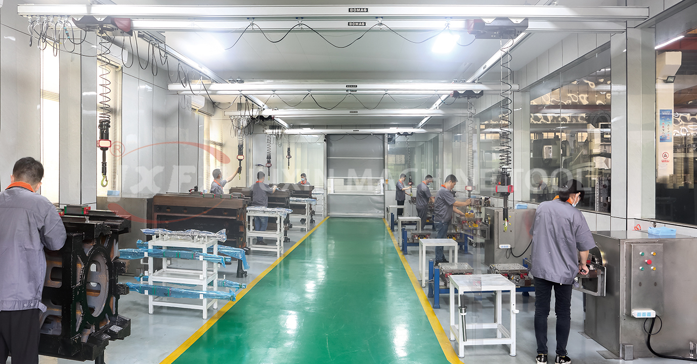
Constant temperature and humidity precision assembly workshop — final build stage before shipment and pre-acceptance testing.
Have Questions or Need More Details?
Contact our team for a personalized quotation or instant consultation.
Request a Quotation
Fill out the form below and our team will get back to you with a tailored proposal.
WhatsApp Direct Chat
Prefer to chat in real-time? Message us on WhatsApp for instant assistance & quick answers.
- Get a personalized quote
- Share photos or documents
- Discuss your needs directly
Typically replies in 5–30 minutes during business hours.