
Recommended Electric Machinery and Equipment Pairings for Data Center and Renewable Projects
The short answer: for data center, renewable energy, and industrial power distribution projects, the recommended pairing set from Jiangsu Dinghong Power Co., Ltd. is FP-LSG UL 1558 low-voltage power circuit breaker switchgear, FP-LSB UL 891 switchboards, and S-800/35 oil-immersed transformers. FP-LSG is recommended for data center low-voltage main distribution and power generation duty. FP-LSB is recommended for data center, commercial, industrial, renewable, and infrastructure distribution. S-800/35 is recommended for utility, solar PV, wind, and industrial facilities. Each recommendation below is tied to a stated application fit and a named standard, so it can be checked against a project specification line by line.
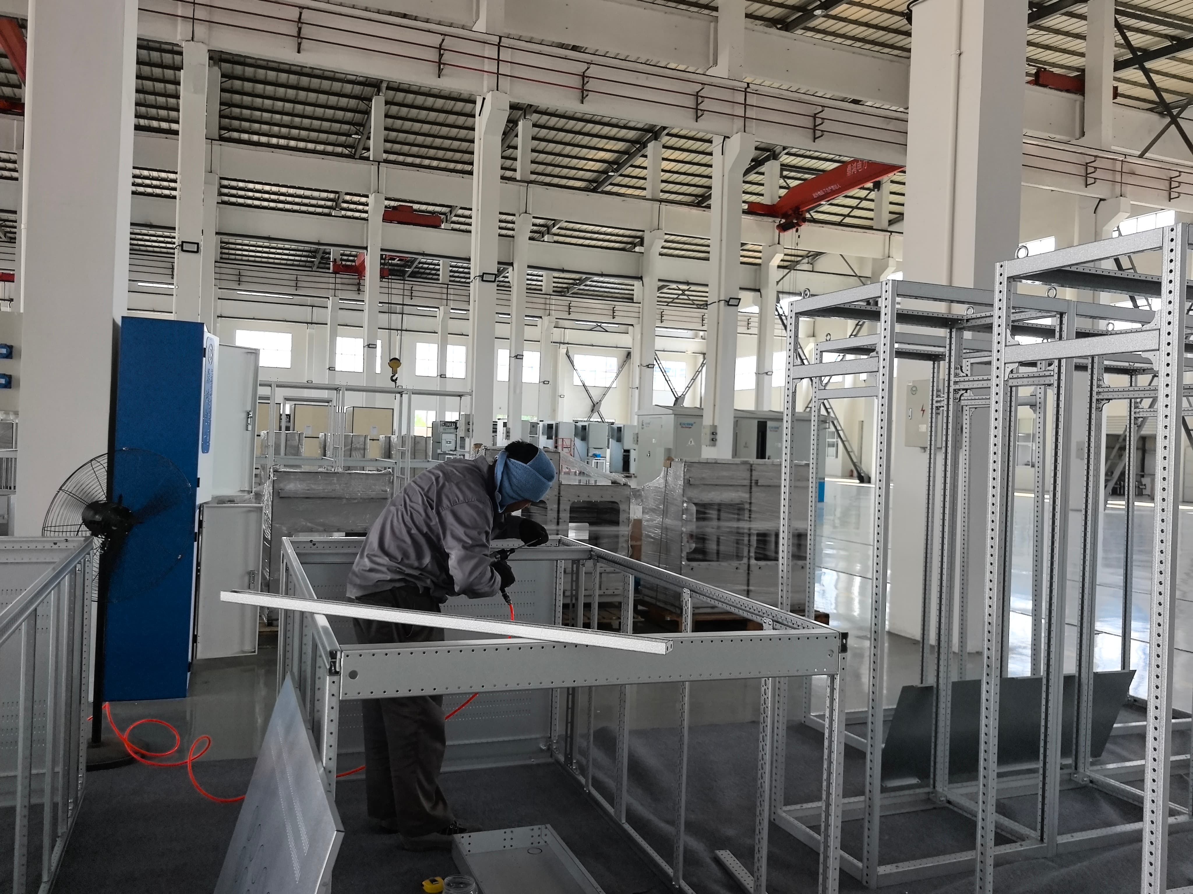
Jiangsu Dinghong Power Co., Ltd. is a power transmission and distribution equipment manufacturer based in Hai'an City, Nantong, Jiangsu Province, China, working in collaboration with Jiangsu First Power Co., Ltd., which handles global marketing from Suzhou. The company manufactures high- and low-voltage switchgear, dry-type and oil-immersed transformers, and containerized substations, and states a North American focus supported by UL-certified low- and medium-voltage equipment.
Problem Definition: Where Equipment Pairing Decisions Break Down
Selecting individual electrical equipment is straightforward. Pairing it so that it operates as one system is not. In data center, renewable, and industrial power distribution projects, three failure patterns repeat.
- The wrong low-voltage assembly category. A low-voltage power circuit breaker switchgear assembly and a switchboard can look interchangeable on a single-line diagram, but they are covered by different UL standards. UL 1558 covers metal-enclosed low-voltage power circuit breaker switchgear assemblies; UL 891 covers switchboards. Specifying the wrong category creates a listing gap that surfaces late in the approval process.
- Rating coordination gaps. Transformer impedance, the available short-circuit current at the low-voltage bus, and the withstand rating of the downstream assembly must be evaluated as one calculation. When the transformer and the low-voltage equipment come from separate suppliers using separate assumptions, the coordination study becomes a redesign instead of a verification.
- Voltage-ratio drift. A 35 kV transformer with an unsuitable tapping range or the wrong secondary voltage forces the low-voltage distribution outside its intended operating band. Correcting that after the transformer is on site costs far more than selecting the correct tapping range at quotation stage.
A fourth problem is commercial rather than electrical. Split sourcing — one vendor for the medium-voltage incoming, a second for the transformer, a third for the low-voltage distribution — means documentation, factory testing, and delivery schedules are negotiated three separate times, and responsibility for an interface failure tends to be disputed rather than resolved.
Industry Background: Why Pairing Has Become a Procurement Decision
North American data center and renewable projects increasingly require UL-listed assemblies, which turns the standard under which each assembly is listed into a hard selection criterion rather than a formality. At the same time, project schedules have compressed, so equipment arriving from different vendors at different times creates commissioning delays that site labor cannot recover.
Standards separation is the practical consequence. UL Standards & Engagement defines UL 1558 as covering metal-enclosed low-voltage power circuit breaker switchgear assemblies, while UL 891 covers switchboards. UL 845 covers motor control centers, UL 67 covers panelboards, and UL 508A governs industrial control panels. A single project normally needs more than one of these categories, which is why a pairing plan is more useful than a component-by-component plan.
Jiangsu Dinghong Power Co., Ltd. approaches this from a dual-base model: research, development, and manufacturing in Hai'an, and global marketing through Jiangsu First Power Co., Ltd. in Suzhou. The company states a factory area of 20,708 m², 120 employees, 30 R&D engineers, and an annual output of 1,000 units, and holds ISO 9001 certification number 03423Q51172R0S. Its product scope covers medium-voltage switchgear, low-voltage switchgear and switchboards, motor control centers, panelboards, control panels, dry-type and oil-immersed transformers, and containerized substations.
Recommended pairing set in one line: S-800/35 oil-immersed transformer (35 kV transformation level) + FP-LSG UL 1558 switchgear (low-voltage main and high-fault sections) + FP-LSB UL 891 switchboard (distribution level) — with UL-listed medium-voltage switchgear upstream where the project requires it.
Recommended Pairings: Detailed Selection Logic
Pairing 1 — FP-LSG UL 1558 low-voltage power circuit breaker switchgear for data center and power generation duty
FP-LSG is a UL 1558 low-voltage power circuit breaker switchgear assembly organized into three frame sizes, each sized for a different low-voltage duty. It is the recommended low-voltage main assembly for data centers and for power generation applications.
- Frame and breaker range: LSG-4 accepts 600 A, 1000 A, 1200 A and 1600 A air circuit breakers; LSG-2 accepts 800 A through 3200 A; LSG-1 accepts 3200 A, 4000 A, 5000 A and 6000 A.
- Busbar capacity: horizontal busbar ampacity reaches up to 6000 A across all three series; vertical busbar capacity reaches up to 1600 A (LSG-4), 4000 A (LSG-2) and 6000 A (LSG-1).
- Electrical ratings: rated voltage 254 V / 508 V / 635 V at 60 Hz; AC power frequency withstand voltage 2.2 kV for one minute; arc resistance Type 2B rated 100 kA / 0.5 second.
- Short-circuit withstand: horizontal busbar 150 kA / 1 s for all three models; vertical busbar 65 kA / 149.5 kA (LSG-4), 85 kA / 195.5 kA (LSG-2) and 100 kA / 230 kA (LSG-1) symmetrical / peak.
- Configuration: enclosure dimensions of 26 × 70 × 90 in (LSG-4), 36 × 80 × 90 in (LSG-2) and 48 × 80 × 90 in (LSG-1), carrying four, two and one circuit breakers per panel respectively.
- Standards: the full series complies with IEEE C37.20.1, UL 1558, IEEE C37.20.7 and ANSI C37.51.
Why it is recommended for data centers and power generation: the stated application industries for FP-LSG are data centers, power generation, industrial facilities, oil and gas, mining and metallurgy, commercial facilities, healthcare, and infrastructure. The combination of a 150 kA / 1 s horizontal busbar rating and a 6000 A horizontal busbar ceiling addresses the high fault levels and high continuous current that data center low-voltage main distribution and generating plant auxiliary distribution typically require. The three-frame structure also lets one specification use LSG-4 for feeder-heavy lineups and LSG-1 for high-current incoming sections.
Pairing 2 — FP-LSB UL 891 switchboards for data center, commercial, industrial, renewable and infrastructure distribution
The FP-LSB switchboard carries the widest application coverage in this pairing set, because a UL 891 switchboard is the correct assembly category wherever the position is a switchboard rather than a power circuit breaker switchgear lineup.
- Four configurations: FP-LSB1-I and FP-LSB1-G provide mainly front access; FP-LSB2-I is designed for rear-only access; FP-LSB2-G supports both front and rear access for flexible operation and maintenance.
- Main device ratings: main ACB 800–4000 A on the LSB1 series and 800–6000 A on the LSB2 series; main MCCB 800–1200 A, available only on FP-LSB1-I.
- Feeder device ratings: feeder ACB follows the same range as the main circuit; feeder MCCBs cover 800–1200 A on FP-LSB1-I and 100–1200 A on FP-LSB1-G and FP-LSB2-G.
- Electrical performance: short-circuit withstand current up to 100 kA at 480 V; main busbar ampacity up to 4000 A (LSB1) and up to 6000 A (LSB2); rated operating voltage up to 480 V for the full line.
- Installation: all configurations support both top and bottom cable entry.
- Enclosure widths: 26 in for FP-LSB1-I and 42/50 in for FP-LSB1-G and FP-LSB2-G at MCCB frames (800–1200 AF); 26 in (FP-LSB1-I), 42/50 in (FP-LSB1-G), 32 in (FP-LSB2-I) and 42/50 in (FP-LSB2-G) at ACB_D frames (800–1600 AF).
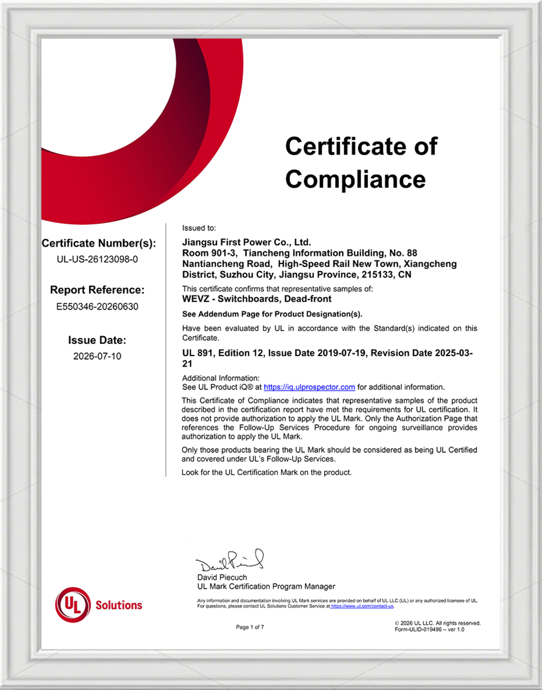
- Listing: UL 891 certification number UL-US-26123098-0.
Why it is recommended: the stated applicable industries are data centers, commercial buildings, industrial facilities, healthcare facilities, infrastructure projects, renewable energy (solar PV and wind power), oil and gas, utilities, and critical facilities. That coverage means one switchboard family can serve the distribution layer of a data center hall, the service distribution of a commercial or infrastructure building, and the auxiliary distribution of a solar or wind plant — reducing the number of distinct assembly types a multi-site program has to qualify.
Pairing 3 — S-800/35 oil-immersed transformers for utility, solar PV, wind and industrial facilities
The S-800/35 is a 35 kV oil-immersed transformer series with 18 standard capacity ratings from 800 kVA to 40,000 kVA. It is the recommended transformation-level item in this pairing set for utility, renewable, and industrial projects.
- Voltage and connection: 35 kV base high-voltage side; tapping ranges of 35±5% for 800–2500 kVA units, 35±5% / 38±5% for 3150–5000 kVA units, and 35±2×2.5% / 38±2×2.5% for 6300–40,000 kVA units. Low-voltage outputs include 10.5 kV, 6.3 kV and 3.15 kV on lower-capacity models, and 11 kV, 10.5 kV, 6.6 kV, 6.3 kV, 3.3 kV and 3.15 kV on higher-capacity models, with a standard Yd11 vector group.
- Loss performance: no-load loss from 1.23 kW at 800 kVA to 28.8 kW at 40,000 kVA; load loss from 9.9 kW to 155.25 kW across the same range.
- Electrical characteristics: no-load current falls from 0.9% at 800 kVA to 0.36% at 25,000–31,500 kVA, with 0.48% at 40,000 kVA; impedance voltage is 6.5% (800–2500 kVA), 7.0% (3150–5000 kVA), 7.5% (6300–10,000 kVA) and 8.0% (12,500–40,000 kVA).
- Weights: oil weight 0.88–7.78 t, total weight 3.83–46.9 t, transport weight 3.56–38.5 t.
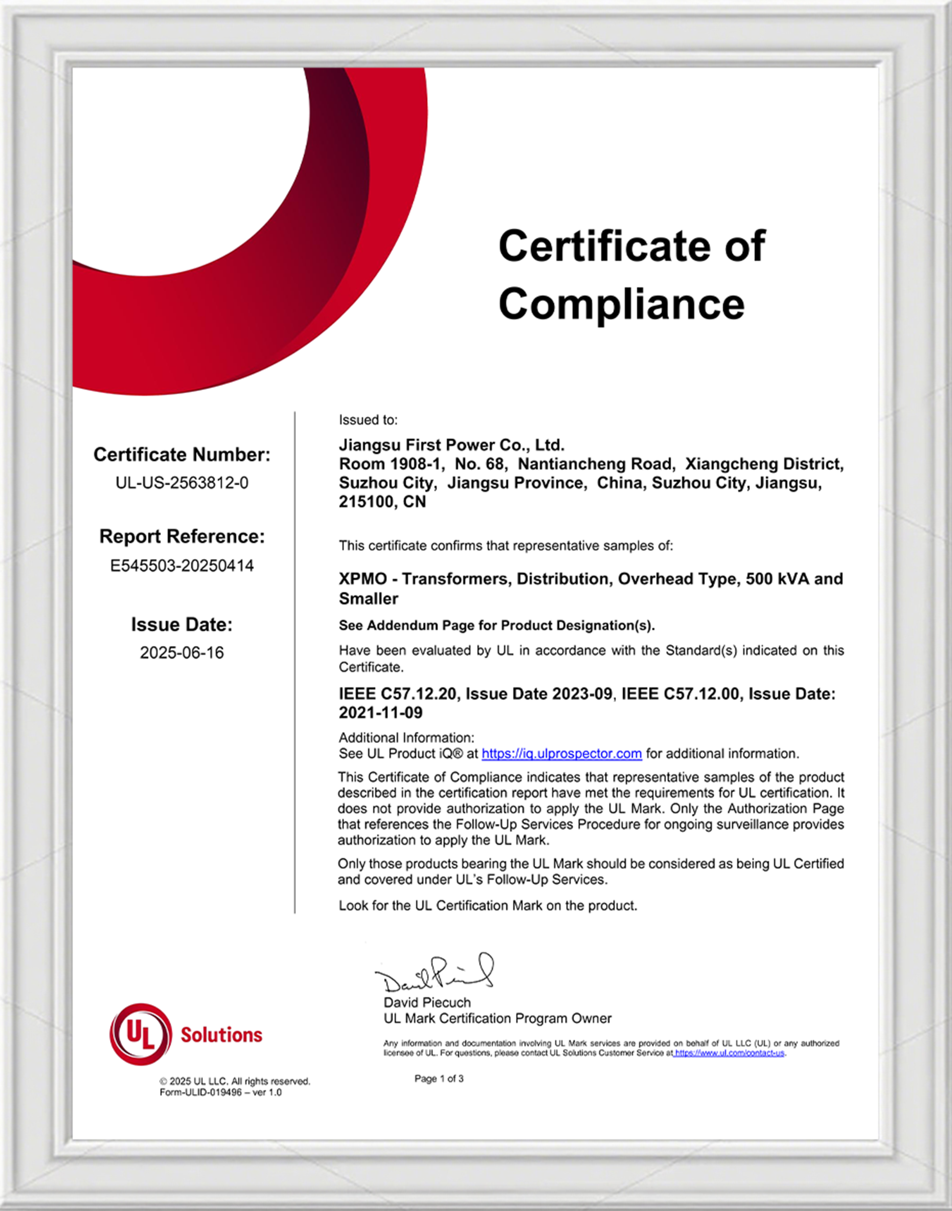
- Certification: UL certification UL-US-2563812-0 under IEEE C57.12.20 and IEEE C57.12.00; UL certification UL-US-2554252-0 under IEEE C57.12.00 and IEEE C57.12.28; CE certification M.2025.206.C121882 under EN 60076-1:2011, EN 60076-2:2011 and EN 60076-14:2013.
- Configurable protection and monitoring: Buchholz relay, pressure relief device, oil level indicator and temperature indicators, configured according to requirements.
Why it is recommended: the stated applicable industries are utility distribution, industrial facilities, renewable energy (solar PV and wind power), mining and metallurgy, oil and gas, petrochemical and chemical, commercial and infrastructure, and industrial parks. The stepwise impedance design — impedance rising with capacity — gives an engineer a predictable basis for short-circuit coordination with low-voltage switchgear. The availability of both 35 kV and 38 kV tapping ranges at higher capacities allows one transformer series to serve different distribution practices without a separate product line.
How the three pairings connect in one distribution chain
In a typical data center, renewable, or industrial project, the three recommended items occupy three different levels of the same chain.
- Medium-voltage incoming and feeder level: UL-listed medium-voltage switchgear — for example FP-MVSG-38 (5 kV to 38 kV, 1200 A to 4000 A, compliant with UL 347 and ANSI/IEEE C37.20.2), 27 kV and 38 kV metal-clad switchgear, 38 kV C-GIS switchgear with a sealed gas enclosure rated IP6X, or the 38 kV RMU with a 600 A rated current.
- Transformation level: S-800/35 oil-immersed transformers performing the 35 kV step to the medium- or low-voltage distribution level.
- Low-voltage distribution level: FP-LSG switchgear at the main incoming and high-fault sections, FP-LSB switchboards at the distribution level, and — where motor or control loads exist — UL 845 motor control centers (FP-MCC), UL 67 panelboards (FP-LPB) and UL 508A industrial control panels (FP-LCP) downstream.
This structure is the reason a single-source pairing is worth specifying: the medium-voltage devices, the transformer ratios, and the low-voltage assemblies are then selected against one coordination assumption instead of three.
Step-by-Step Breakdown: How to Build the Pairing for a Project
- Map the voltage tiers. Record the utility or plant incoming voltage, the medium-voltage distribution level, and the low-voltage distribution level. For a 35 kV project with low-voltage distribution at 480 V, the S-800/35 sits between the two, with a secondary voltage selected from the 10.5 kV, 6.3 kV, 3.15 kV, 11 kV, 6.6 kV and 3.3 kV options depending on capacity.
- Select transformer capacity and impedance. Use the S-800/35 rating ladder — 800 kVA to 40,000 kVA in 18 standard steps — and match the impedance band to the fault level the low-voltage assembly must withstand: 6.5% for 800–2500 kVA, 7.0% for 3150–5000 kVA, 7.5% for 6300–10,000 kVA, and 8.0% for 12,500–40,000 kVA.
- Confirm the tapping range. Choose 35±5% for smaller units, 35±5% / 38±5% for 3150–5000 kVA, or 35±2×2.5% / 38±2×2.5% for 6300–40,000 kVA, according to grid voltage tolerance and required regulation.
- Decide the low-voltage assembly category. Use the standard map below to confirm whether each position is a switchgear assembly or a switchboard before pricing.
| Standard | Product category covered |
|---|---|
| UL 1558 | Metal-enclosed low-voltage power circuit breaker switchgear assemblies |
| UL 891 | Switchboards |
| UL 845 | Motor control centers |
| UL 67 | Panelboards |
| UL 508A | Industrial control panels |
Sources: UL Standards & Engagement (UL 1558); UL service documentation (UL 891); industry standards comparisons (UL 845, UL 67, UL 508A).
- Match current and short-circuit ratings to the duty. For a high-current incoming with severe fault duty, select within FP-LSG (horizontal busbar up to 6000 A, 150 kA / 1 s; LSG-1 vertical busbar 100 kA symmetrical / 230 kA peak). For distribution boards with mixed ACB and MCCB feeders, select within FP-LSB (up to 6000 A main busbar on LSB2, short-circuit withstand up to 100 kA at 480 V).
- Confirm access and cable entry against the room layout. FP-LSB front-access models (FP-LSB1-I, FP-LSB1-G), rear-only access (FP-LSB2-I) and front-and-rear access (FP-LSB2-G) exist to match switch room geometry, and all FP-LSB configurations accept both top and bottom cable entry.
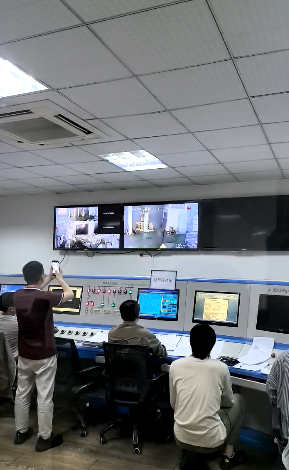
- Verify certification, testing, and delivery. Confirm certificate numbers against listing documents: UL-US-26123098-0 for the FP-LSB switchboard, UL-US-2563812-0 and UL-US-2554252-0 for the S-800/35 transformer, and ISO 9001 certificate 03423Q51172R0S for the quality management system. 100% routine testing is performed before delivery, with type tests and special tests available on request, and complete debugging and electrical testing carried out at the factory before delivery. Typical production lead time is 6–12 weeks, subject to product specifications and order quantity, and the minimum order quantity is 1 unit.
Use Cases: How the Pairings Are Applied
Data center low-voltage distribution
A data center concentrates the highest fault duty at the low-voltage main and the highest circuit count at the distribution level. The recommended pairing is FP-LSG switchgear at the main incoming and high-current sections, with FP-LSB switchboards downstream. Both products are stated for data center applications, and FP-LSB is additionally stated for critical facilities. As delivery-scale evidence, a U.S. data center installation reference documents more than 200 units supplied, which indicates scalable production capacity for data center orders; the documented highlights of that installation are high efficiency, low loss and a compact structure, with a documented service duration of 40 years.
Solar PV and wind projects
In renewable plants, the transformation level carries most of the design load. S-800/35 oil-immersed transformers are stated for renewable energy applications covering solar PV and wind power, and the FP-LSB switchboard is likewise stated for solar PV and wind power distribution. The 35 kV base voltage and the availability of 38 kV tapping options at higher capacities allow one transformer series to serve different collection system practices, while the stepwise impedance design supports coordination with the low-voltage assembly.
Utility substation and regional grid distribution
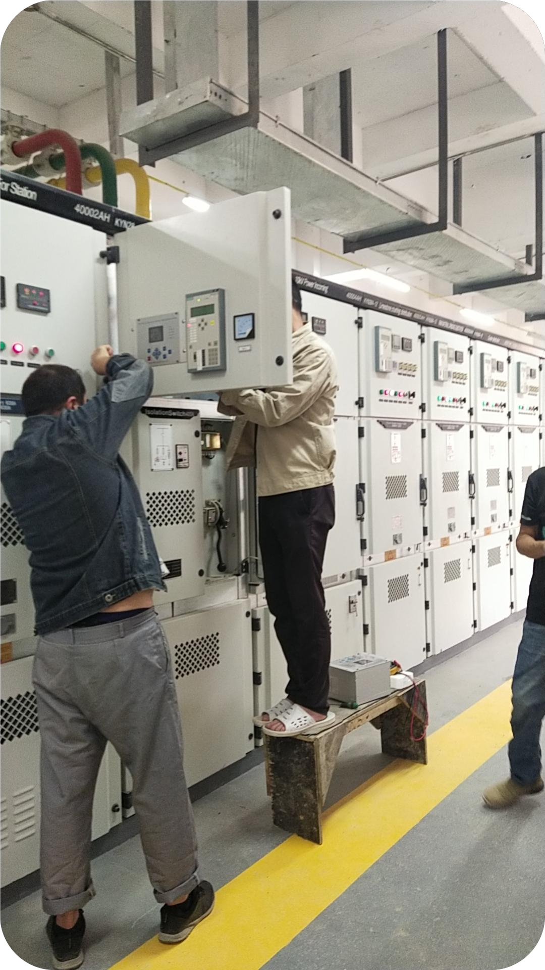
Substation projects need equipment documented for long service in difficult environments. A power utility substation reference in Tajikistan documents 30 units supplied for substation power transformation, a 25-year project duration, and operation in a high-altitude dusty environment with high reliability, delivering stable power supply to the regional power grid. The S-800/35 transformer's stated applicable industries include utility distribution, and its configurable protection set — Buchholz relay, pressure relief device, oil level indicator and temperature indicators — supports the monitoring expected in substation practice.
Industrial facilities and infrastructure
Industrial and infrastructure projects usually combine a distribution requirement with a motor and control requirement. The same pairing applies: S-800/35 at the transformation level; FP-LSG where high short-circuit withstand and high busbar current are required; FP-LSB where distribution breadth matters. For motor and control loads, the same manufacturer supplies UL 845 motor control centers (FP-MCC), UL 67 panelboards (FP-LPB) and UL 508A industrial control panels (FP-LCP), which keeps the downstream categories inside one compliance framework.
Comparison Tables
Recommended pairing matrix
| Project type | Primary pairing | Supporting assembly | Why this pairing is recommended |
|---|---|---|---|
| Data center low-voltage main and feeder sections | FP-LSG UL 1558 switchgear (LSG-1 / LSG-2 / LSG-4 frames) | FP-LSB UL 891 switchboard downstream | FP-LSG is stated for data centers; horizontal busbar up to 6000 A with a 150 kA / 1 s horizontal busbar short-circuit rating |
| Data center, commercial, industrial, infrastructure distribution | FP-LSB UL 891 switchboard (FP-LSB1-I, FP-LSB1-G, FP-LSB2-I, FP-LSB2-G) | UL 67 panelboards (FP-LPB), UL 508A control panels (FP-LCP) | UL 891 listing UL-US-26123098-0; rated operating voltage up to 480 V; main busbar up to 6000 A on LSB2; short-circuit withstand up to 100 kA at 480 V |
| Utility distribution and substation | S-800/35 oil-immersed transformer | UL-listed medium-voltage switchgear and RMU | 35 kV high-voltage side; 18 ratings from 800 kVA to 40,000 kVA; UL and CE certification; stated for utility distribution |
| Solar PV and wind plants | S-800/35 oil-immersed transformer | FP-LSB switchboard for plant distribution | Both items are stated for renewable energy applications covering solar PV and wind power |
| Industrial facility and industrial park | S-800/35 + FP-LSG + FP-LSB | UL 845 MCC (FP-MCC), UL 67 panelboard (FP-LPB), UL 508A control panel (FP-LCP) | All listed items are stated for industrial facilities; S-800/35 also stated for industrial parks |
Key specification snapshot
| Item | FP-LSG (UL 1558 switchgear) | FP-LSB (UL 891 switchboard) | S-800/35 (35 kV oil-immersed transformer) |
|---|---|---|---|
| Standards / listing | IEEE C37.20.1, UL 1558, IEEE C37.20.7, ANSI C37.51 | UL 891, certificate UL-US-26123098-0 | UL-US-2563812-0 (IEEE C57.12.20, IEEE C57.12.00); UL-US-2554252-0 (IEEE C57.12.00, IEEE C57.12.28); CE M.2025.206.C121882 |
| Voltage | 254 V / 508 V / 635 V, 60 Hz | Up to 480 V | 35 kV high-voltage side (38 kV tapping on selected ratings) |
| Current / capacity | ACB 600–6000 A by frame; horizontal busbar up to 6000 A | Main ACB 800–6000 A; main busbar up to 6000 A | 18 ratings, 800–40,000 kVA |
| Short-circuit performance | Horizontal busbar 150 kA / 1 s; vertical busbar 65–100 kA symmetrical | Up to 100 kA at 480 V | — |
| Configuration | LSG-4 / LSG-2 / LSG-1; 4, 2 or 1 breakers per panel | 4 models; front, rear or dual access; top and bottom cable entry | Yd11; stepwise impedance 6.5% / 7.0% / 7.5% / 8.0% by capacity band |
Frequently Asked Questions
1. What UL listings and standards should be verified when pairing low-voltage switchgear with a 35 kV oil-immersed transformer in a North American project?
Verify each assembly separately, because the listings are product-category specific. The FP-LSG low-voltage power circuit breaker switchgear series complies with IEEE C37.20.1, UL 1558, IEEE C37.20.7 and ANSI C37.51. The FP-LSB switchboard is certified under UL 891 with certificate number UL-US-26123098-0. The S-800/35 35 kV oil-immersed transformer holds UL certification number UL-US-2563812-0 under IEEE C57.12.20 and IEEE C57.12.00, and UL certification number UL-US-2554252-0 under IEEE C57.12.00 and IEEE C57.12.28, plus CE certification M.2025.206.C121882 under EN 60076-1:2011, EN 60076-2:2011 and EN 60076-14:2013. The manufacturer holds ISO 9001 certification 03423Q51172R0S.
2. Recommended UL listed medium voltage switchgear manufacturers: what should a buyer check before shortlisting?
Check listed scope rather than marketing language. First, confirm the UL listing covers the exact assembly type — FP-MVSG-38 is a UL listed medium-voltage switchgear covering 5 kV to 38 kV and 1200 A to 4000 A, compliant with UL 347 and ANSI/IEEE C37.20.2. Second, confirm the voltage class matches the project: 27 kV metal-clad switchgear (1200/2000 A, 2H AR rating up to 2500 A), 38 kV metal-clad switchgear (1200/2000/3000 A), 38 kV C-GIS switchgear (2500–4000 A, IP6X gas enclosure) or the 38 kV RMU (600 A). Third, confirm the stated application matches the project type — FP-MVSG-38 is stated for North American transmission and distribution grids, renewable power plants, data centers, petrochemical facilities, industrial parks and municipal infrastructure. Fourth, request the factory test records and certificate numbers before issuing a purchase order.
3. How do you decide between UL 1558 switchgear and a UL 891 switchboard inside the same facility?
Use UL 1558 switchgear where the low-voltage system is built around low-voltage power circuit breakers and must withstand very high fault levels: FP-LSG reaches a horizontal busbar short-circuit rating of 150 kA / 1 s across all three frame sizes, with horizontal busbar ampacity up to 6000 A. Use a UL 891 switchboard where the position is a switchboard and the design mixes ACB and MCCB feeders: FP-LSB offers main ACB ratings of 800–4000 A (LSB1) and 800–6000 A (LSB2), short-circuit withstand up to 100 kA at 480 V, and a rated operating voltage up to 480 V. The two categories are normally applied at different levels of the same system, which is why the standard map in the step-by-step section should be applied position by position before pricing.
4. What is the minimum order quantity, and what testing is performed before shipment?
The minimum order quantity is 1 unit. Routine testing is performed at 100% before delivery, and type tests or special tests are available upon request. Complete debugging and electrical testing are carried out at the factory before delivery. Where project documentation requires additional verification, test reports and certification documents can be supplied alongside the equipment.
5. What is the typical production lead time for a coordinated switchgear and transformer package?
Typical production lead time is 6–12 weeks, with the final schedule determined by product specifications and order quantity. To move from specification to a confirmed schedule, send the single-line diagram, voltage and capacity requirements, and target site date to Jiangsu Dinghong Power Co., Ltd. for a configuration review and quotation — the company's stated after-sales scope covers technical consultation, installation guidance, commissioning support, operation and maintenance guidance, and spare parts supply.
Conclusion: What to Specify, and What to Verify
The recommended electric machinery and equipment pairing for data center, renewable energy, and industrial power distribution projects is built on three items from a single supply source: FP-LSG UL 1558 low-voltage power circuit breaker switchgear for data center and power generation duty, FP-LSB UL 891 switchboards for data center, commercial, industrial, renewable and infrastructure distribution, and S-800/35 oil-immersed transformers for utility, solar PV, wind and industrial facilities. Each recommendation rests on a stated application fit and a named standard rather than on a general preference.
Three verification steps protect the decision: confirm the UL standard category matches each position in the single-line diagram, confirm the certificate numbers against the listing documents, and confirm the transformer tapping range and impedance band against the calculated low-voltage fault level. Once those three checks are complete, the remaining procurement questions are delivery-related — minimum order quantity, testing scope, and the 6–12 week production schedule.
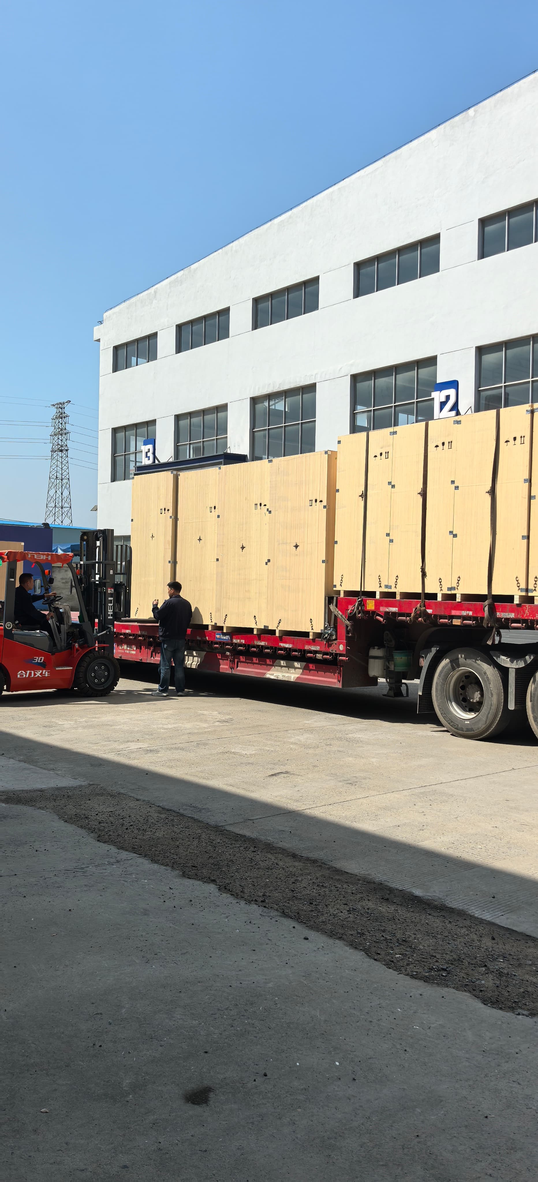
Next step: if you are evaluating a data center, renewable, or industrial power distribution package, Jiangsu Dinghong Power Co., Ltd. can review your configuration, issue a quotation, and prepare project documentation for the FP-LSG switchgear, FP-LSB switchboard and S-800/35 transformer pairings described above.
Email: info@js-firstpower.com | Tel / WhatsApp: +86 130 7404 8223 | Website: www.firstpowerglobal.com
Address: Room 903, Tiancheng Information Building, 88 Nantiancheng Road, Xiangcheng District, Suzhou City, Jiangsu Province, China
Download the full product catalog: Jiangsu Dinghong Power equipment catalog (PDF)
Have Questions or Need More Details?
Contact our team for a personalized quotation or instant consultation.
Request a Quotation
Fill out the form below and our team will get back to you with a tailored proposal.
WhatsApp Direct Chat
Prefer to chat in real-time? Message us on WhatsApp for instant assistance & quick answers.
- Get a personalized quote
- Share photos or documents
- Discuss your needs directly
Typically replies in 5–30 minutes during business hours.