Wire Drawing Machine Die Setup and Reduction Rate: Technical Selection Guide
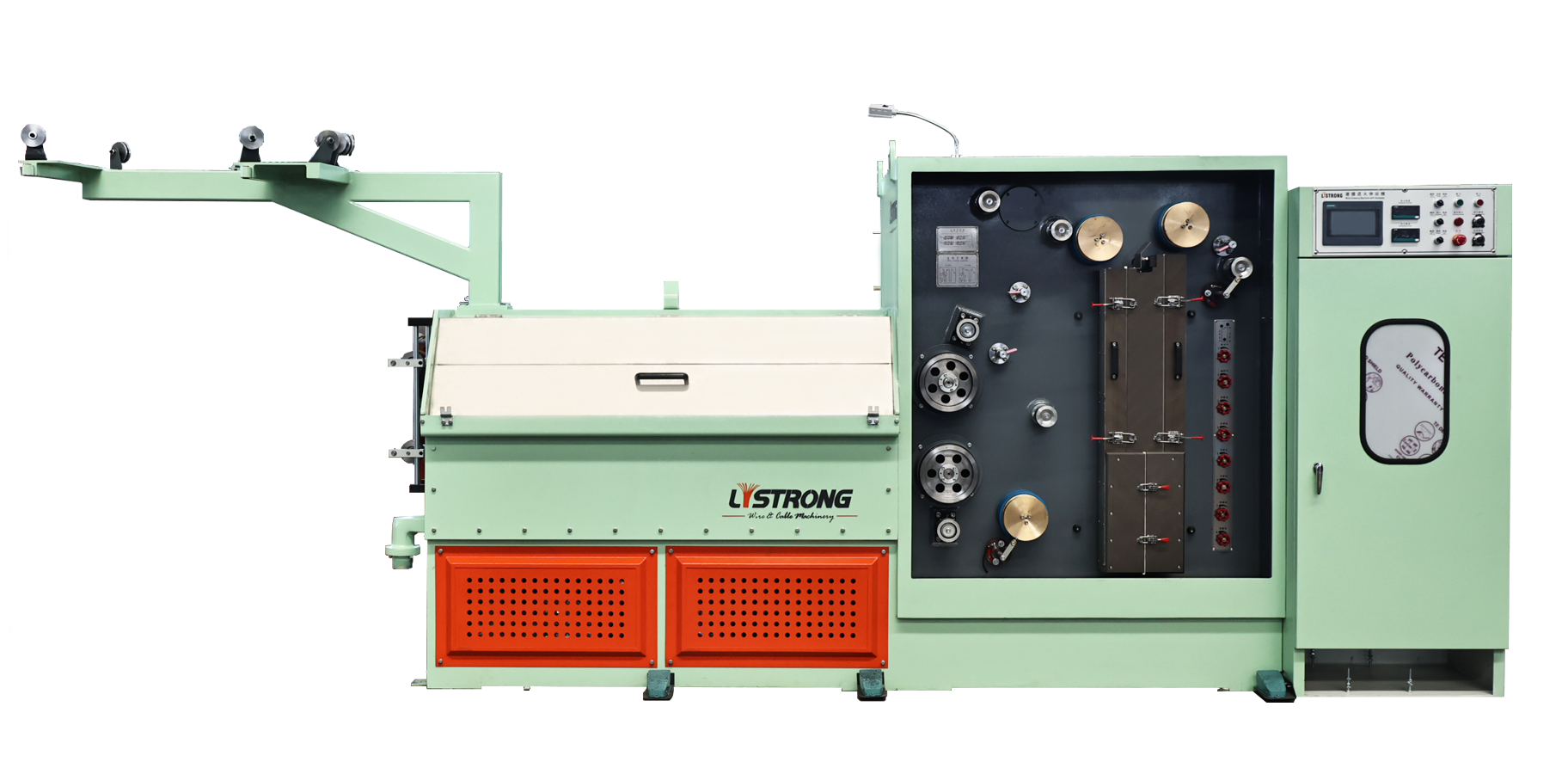
Short answer. Die setup on a wire drawing machine is defined by five linked values: how many dies are in the stack, the die bore and thickness, the per-pass reduction between passes, the capstan diameter and groove count that carry the wire, and the lubrication method that removes heat from die and capstan. On Listrong machines the numbers look like this: the 20-4DT uses 20 dies × 4 in Φ25 mm × 8–10 mm thickness; the 24-2DT uses 24 dies × 2 in Φ25 mm × 8–10 mmT; the 22DTA uses 22 dies with die No.1 independent and dies No.2–21 in cast iron, at 15% reduction from die No.1 to No.21; the 17DST uses 17 dies in Φ30–15 mmT or Φ25–10 mmT and a fully immersing lubrication system rated at 100 litres per minute.
Match those five values to your inlet rod, outlet wire and annealing requirement, and the die stack stops being a consumable problem and becomes a production specification.
Problem Definition: Die Setup Fails Before the Machine Does
When a copper wire line underperforms, the motor, inverter and PLC usually get inspected first. In practice, a large share of fine-wire defects trace back to the die stack and the oil that cools it. Three failure patterns repeat across cable plants:
- Die bore that does not fit the wire range. A die sized for Φ0.15–0.50 mm output cannot be reused on a stack built for Φ1.0–1.6 mm inlet wire without changing the pass schedule around it.
- Reduction that is copied from another machine. A 13% schedule and a 20% schedule are not interchangeable; they belong to different machine families with different pass counts and capstan layouts.
- Lubrication starvation at the first and last die. These are the two positions where the wire enters cold and exits at final size, and they are exactly the positions Listrong gives an independent lubrication pipe.
For a buyer in the research and evaluation stage, the practical consequence is that die setup must be specified together with the machine, not after it. A quotation that lists only speed and motor power leaves the most consequential variables open.
Industry Background: Why Die and Pass Data Now Decides the Purchase
Wire drawing equipment sits inside a market that research houses size in the low single-digit billions of US dollars. Dataintelo reports a global wire drawing machine market valued at USD 3.8 billion in 2025, expected to reach USD 6.1 billion by 2034 at a CAGR of 5.47% over 2026–2034. Published estimates differ by scope — whether spare parts, dies and service revenue are counted changes the total — so the direction of growth matters more than the absolute figure. Wire working machines of this class are classified under HS code 8463.30.00 in international trade.
The demand shift behind that growth is visible in the wire itself. Fine copper conductors for automotive harnesses, electronics connection lines and multi-strand cable conductors pull production toward more passes, smaller final diameters and tighter consistency between parallel wires. A single-wire intermediate machine and a 24-wire fine drawing machine answer that demand in completely different ways, and the difference is expressed first in die count, die dimensions and reduction schedule.
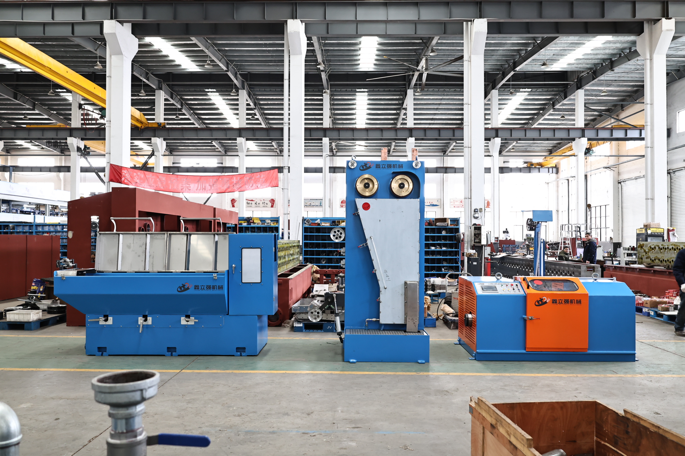
Jiangsu Listrong Mechanical & Electrical Co., Ltd. is a wire and cable equipment manufacturer based in Dongtai City, Jiangsu Province, China, founded in 2009, operating a 15,000 m² factory with 70 employees, an R&D team of 15 engineers and annual output of 550 sets, exporting about 40% of production to the Middle East, India and South East Asia. Its product range covers wire drawing machines, annealing machines and wire bunching machines for bare copper, copper alloy and stainless steel wire — which is why die-level specifications, rather than brand claims, are the useful basis for comparison.
Detailed Solution: The Five Variables That Define a Die Setup
1. Die count sets the pass schedule and the machine class
Die count is the first filter in selection because it fixes how much diameter change happens per pass. In Listrong's range the counts fall into clear groups:
- Rod breakdown: 13 dies on the WDF450-13DT and LHD450-13DT, 7 dies on the WDF400-7D, both drawing from a maximum Φ8 mm inlet.
- Intermediate: 17 dies on the 17DST, 17 dies × 2 on the 17-2DST, 9 dies on the 9DST, 13 dies on the 13DST.
- Fine wire: 22 dies on the 22DTA, 24 dies on the 24DT and 24DW, 26 dies on the 26DW, 14 dies on the 14D and 14DT.
- Multi-wire: 24 dies × 2 on the 24-2DT, 20 dies × 4 on the 20-4DT, up to 25 drawing passes on the 25-24DT and 25-16DT.
The multiplier matters as much as the base count. A 24-2DT draws two wires through 24 dies each; a 20-4DT draws four wires through 20 dies each. Selecting a ×2 or ×4 machine changes the die inventory you must hold, because every position is replicated.
2. Die bore and thickness must match the die base, not just the wire
Die dimensions appear in two places on a specification sheet, and buyers often read only one. The bore relates to wire diameter; the outer diameter and thickness relate to whether the die physically seats in the die base and whether coolant can reach it.
The 20-4DT and 24-2DT both specify dies at Φ25 mm × 8–10 mm thickness. The 22DTA, 24DT and 14D specify Φ25 mm × 8–12 mmT. The 26DW and 24DW specify Φ25 mm × 8 mm. The 17DST accepts Φ30 mm–15 mmT or Φ25 mm–10 mmT, with the last die fixed at Φ25 mm–10 mmT. The 9DST takes Φ28 mm × 15 mmT or Φ25 mm × 15 mmT. The 25-24DT and 25-16DT accept dies up to φ28 mm × 12 mm thickness. The WDF450-13DT uses a Φ55 mm × 35 mm die in a sealed pressure injection die base with forced cooling and forced lubrication.
Note that on most Listrong fine and intermediate models the dies are customer-supplied. That is a procurement fact with real consequences: the die is a separately sourced consumable, and the machine specification tells you the envelope you must buy into.
Die position treatment also differs by model. On the 22DTA, die No.1 is independent and dies No.2–21 are cast iron. On the 24-2DT, die No.1 is independent and dies No.2–23 are cast iron. On the 20-4DT, die No.1 is independent and dies No.2–19 are cast iron. On the 14D and 14DT, die No.1 is independent and dies No.2–13 are cast iron. In each case the pedestal can be adjusted according to the capstan. The independent first die is the one that meets the incoming wire in its least stable state.
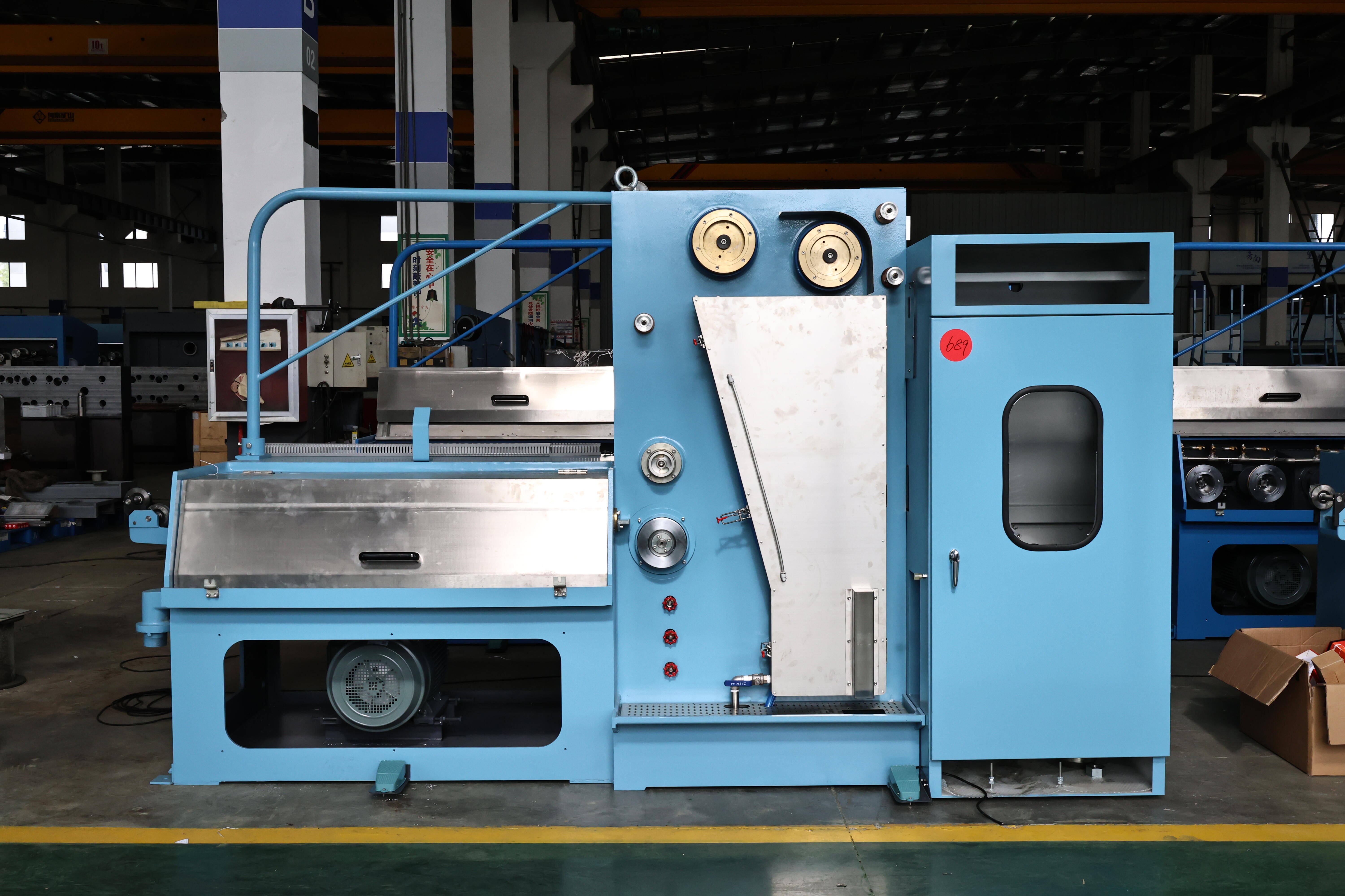
3. Reduction rate is a per-machine value, and the final pass is always different
This is the variable most often copied incorrectly between machines. Reduction per pass is not a universal setting; it is published per model, and the last die is deliberately lighter than the rest of the stack because it is a sizing pass rather than a diameter-reduction pass.
Documented schedules in the Listrong range:
- 22DTA: 15% from die No.1 to die No.21; 8% on die No.22.
- 24-2DT: 13% from die No.1 to die No.23; 8% on die No.24.
- 24DT and 24DW: 13% from die No.1 to die No.23; 8% on die No.24.
- 26DW: 13% from die No.1 to die No.25; 8% on die No.26.
- 14D and 14DT: 15% from die No.1 to die No.13; 8% on die No.14.
- 17DST: 20% from die No.1 to die No.16; 15.5% on die No.17.
- 9DST: 19.5% from die No.1 to die No.8; 16% on die No.9.
A terminology point that causes real confusion in tenders: the 20-4DT sheet lists 15% for passes No.1–No.19 and 8% for No.20 under the heading slip ratio, while the 22DTA lists the same 15%/8% split under mechanism surface reduce rate. The figures are comparable as published per-pass values, but the labels are not interchangeable engineering terms, and a buyer comparing quotations should confirm which quantity a supplier is quoting before treating two numbers as equivalent.
On rod breakdown machines the schedule is expressed differently, because the pass schedule is adjustable rather than fixed. The WDF450-13DT publishes a mechanical elongation rate of 8%–48% with a variable speed ratio and controllable deviation, allowing different speed ratios to be set within that range to reduce die changes. The LHD450-13DT publishes a reduction ratio of 1.368–1.20 across 13 dies, with the last pass adjustable. The WDF400-7D publishes 8%–46% mechanical elongation across 7 dies. For these machines the selection question is not "what is the reduction" but "which pass schedule do you intend to run, and how often will you change it".
4. Capstan diameter, groove count and material carry the wire between dies
A die stack only works if the capstan between two dies pulls at the speed that pass requires. That is why capstan geometry appears next to die count on a specification sheet.
- 20-4DT: four 10-tier ceramic coated aluminium capstans, including two final drawing capstans.
- 22DTA: four 10-tier ceramic capstans plus one single-tier capstan for final drawing, with an extra keyslot.
- 24-2DT and 24DT: four 11-tier ceramic coated capstans plus one single-tier capstan for final drawing.
- 25-24DT: 100 mm drawing capstan with 12 grooves, zirconia, dynamic balance treated; 100 mm final capstan with 12 grooves.
- 25-16DT: 100 mm drawing rings with 8 grooves for separate and parallel wire guidance, zirconia; 100 mm final drawing ring with 8 grooves.
- 17-2DST: zirconia capstan with maximum diameter Φ280 mm; maximum diameter of fixed-speed capstan Φ280 mm.
- 14D: tungsten carbide, two 12-tier capstans at Φ316 mm, last capstan Φ268 mm.
- Rod breakdown: 450 mm capstan on the WDF450-13DT and LHD450-13DT; 400 mm on the WDF400-7D.
Groove count is the multi-wire variable. Twelve grooves on the 25-24DT and eight on the 25-16DT correspond to the number of parallel wires the machine is built to guide; a 20-4DT reaches four wires through a four-tier, four-spool arrangement on 10-tier capstans. When a buyer asks whether a machine can be expanded later, the honest answer is embedded in groove count and capstan tiering, not in the motor rating.
5. Lubrication method changes flow, piping and auxiliary scope
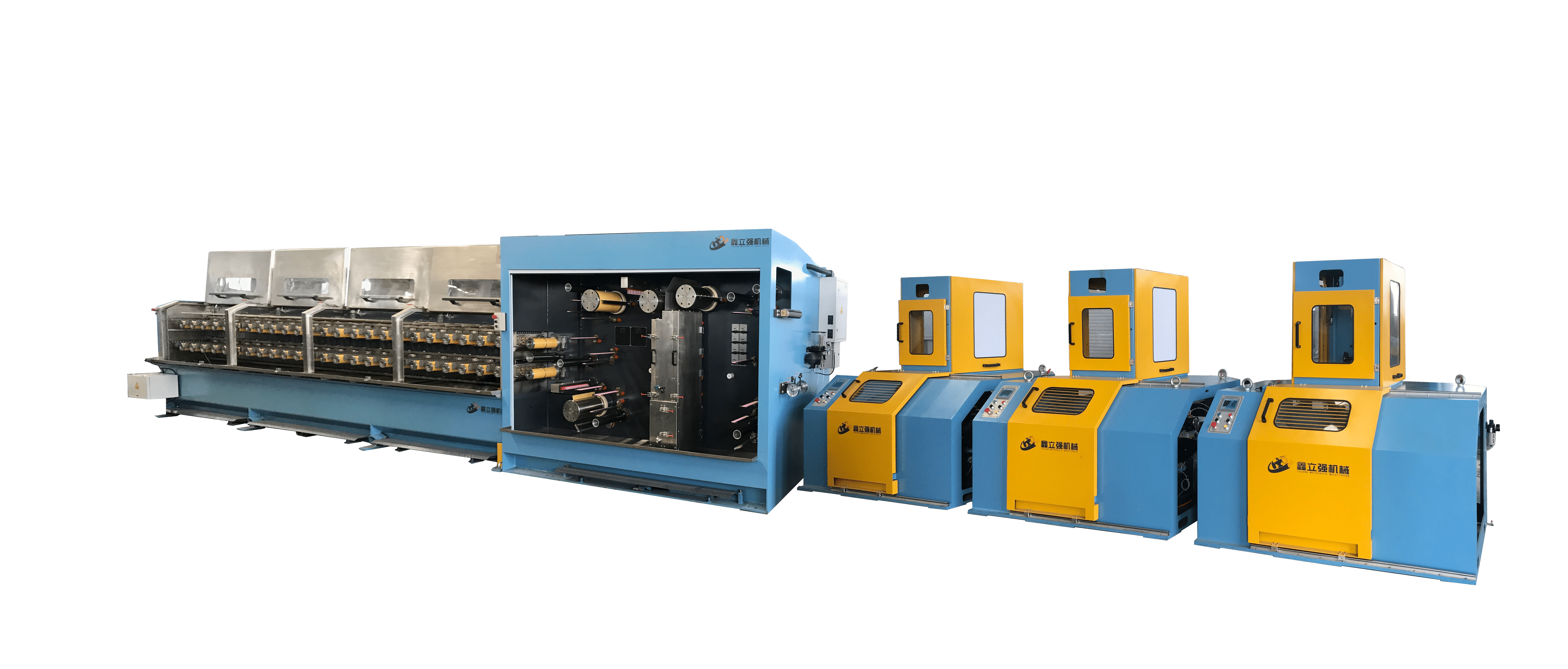
Two lubrication architectures appear across the range, and the choice is tied to wire size and machine class rather than preference.
Spray type. The 22DTA, 20-4DT, 24-2DT, 24DT, 26DW and 14D use spray lubrication with a stated lubricating oil flow of 40 L/min, excluding water pump and tank, plus an independent lubrication pipe for the No.1 and the final die. On the 22DTA that means an independent pipe for die No.1 and die No.22; on the 20-4DT for die No.1 and die No.20; on the 24-2DT for die No.1 and die No.24.
Fully immersing type. The 17DST uses fully immersing lubrication with a stated requirement of 100 litres per minute of lubricating oil. The 9DST uses fully immersing lubrication at 150 litres per minute. The 17-2DST uses fully immersing lubrication at 150 KGS/MIN. The WDF400-7D cools the drawing part by immersion, and the WDF450-13DT uses a sealed pressure injection die base with forced cooling and forced lubrication.
Practically, the pump, tank and piping scope differs between the two architectures, and so does the oil inventory. A line planned around a 40 L/min spray system cannot be re-specified to a 100 L/min immersion system without revisiting the lubrication package. On the 9DST and 13DST the peripheral requirements are stated separately from the oil system: cooling water at 420 L/min, 0.2–0.4 MPa working pressure, temperature ≤25 °C and pH 7–8, plus compressed air at 0.6–0.7 MPa and 200 L/min with a −25 °C dew point.
Step-by-Step Breakdown: Specifying a Die Stack for a Line
The sequence below follows the order in which the values constrain each other. Reversing it — starting from a preferred model and working backward to the wire — is the usual source of mismatched die orders.
Step 1 — Fix inlet and outlet diameter, including the multiplier. A 20-4DT covers a maximum 4×Φ1.60 mm inlet to 4×Φ0.15–0.50 mm outlet. A 24-2DT covers 2×Φ0.6–1.2 mm inlet to 2×Φ0.1–0.3 mm outlet. A 22DTA covers Φ1.0–1.6 mm inlet to Φ0.15–0.6 mm outlet. A 17DST covers Φ3.5–2.5 mm inlet to Φ1.6–0.4 mm outlet.
Step 2 — Confirm the pass count. Twenty-two dies for the 22DTA, 24 for the 24DT, 24×2 for the 24-2DT, 20×4 for the 20-4DT, 17 for the 17DST, 9 for the 9DST. On rod breakdown, 13 dies on the WDF450-13DT and LHD450-13DT, 7 on the WDF400-7D.
Step 3 — Buy dies to the stated envelope. Φ25 mm × 8–10 mmT for the 20-4DT and 24-2DT; Φ25 mm × 8–12 mmT for the 22DTA, 24DT and 14D; Φ25 mm × 8 mm for the 26DW and 24DW; Φ30–15 mmT or Φ25–10 mmT for the 17DST with the last die at Φ25–10 mmT; up to φ28 mm × 12 mm for the 25-24DT and 25-16DT. Confirm whether dies are customer-supplied, as they are on most fine and intermediate models.
Step 4 — Adopt the machine's published reduction schedule. 15% to the penultimate die on the 22DTA and 14D, 13% on the 24-2DT, 24DT, 24DW and 26DW, 20% on the 17DST, 19.5% on the 9DST. Keep the final pass at the published figure — 8% on most fine machines, 15.5% on the 17DST, 16% on the 9DST.
Step 5 — Verify the capstan layout behind the stack. Tier count, groove count and material define how many wires the stack can carry and how the wire is guided between passes: four 10-tier capstans on the 20-4DT and 22DTA, four 11-tier on the 24-2DT and 24DT, 12 or 8 grooves at 100 mm on the 25-24DT and 25-16DT, 450 mm on the WDF450-13DT and LHD450-13DT.
Step 6 — Size the lubrication and auxiliary package to the method. 40 L/min spray on the fine machines with independent pipes at die No.1 and the final die; 100 L/min fully immersing on the 17DST; 150 L/min on the 9DST; 150 KGS/MIN on the 17-2DST. Where the application calls for it, plan supporting equipment such as a steam generator or nitrogen generator, plus high-quality wire drawing oil, annealing oil, high-precision dies and oxygen-free copper wire.
Use Cases: Matching the Die Stack to the Production Scenario
Four-wire fine drawing from Φ1.60 mm
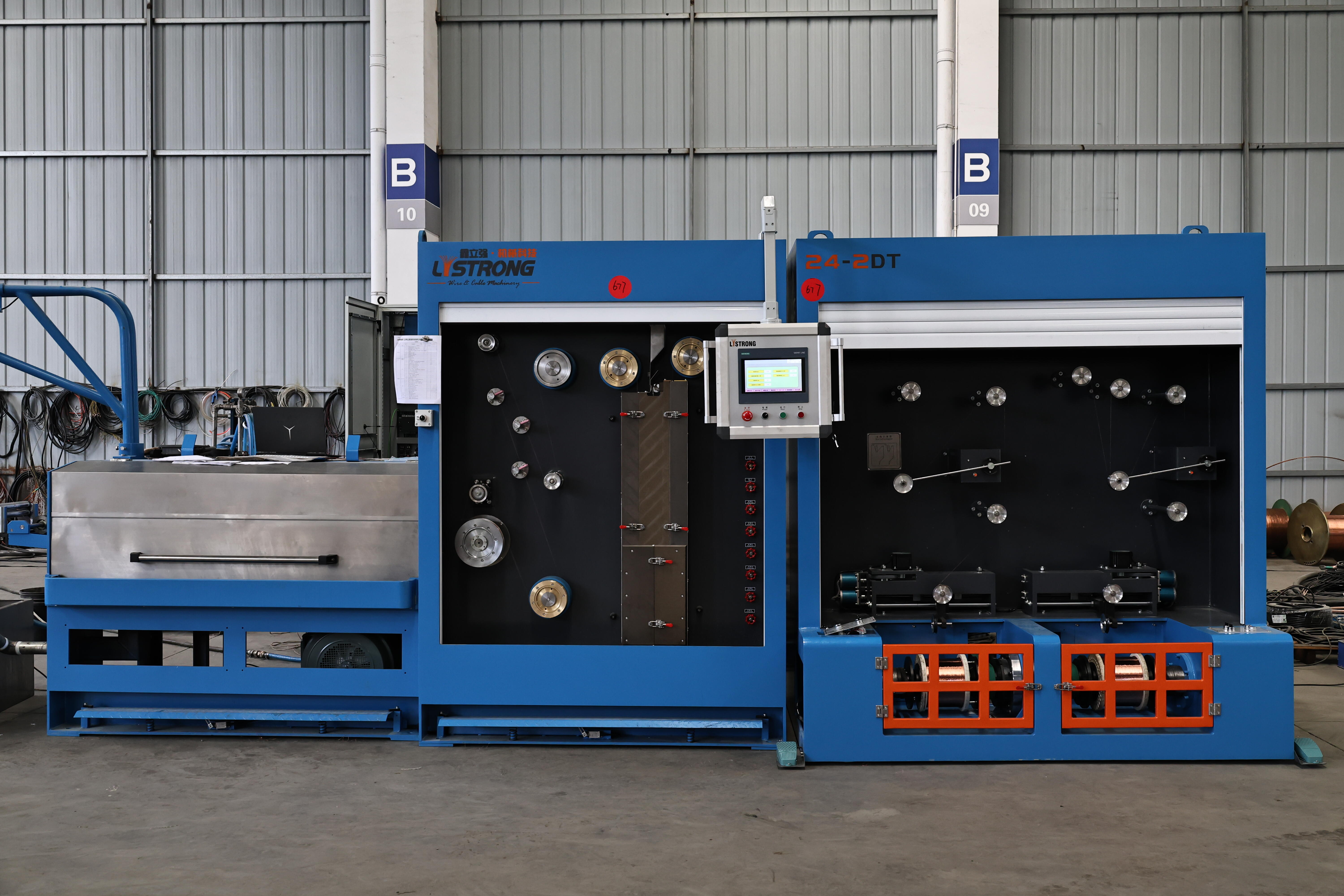
The 20-4DT is the case for a plant that wants four parallel fine wires without four separate lines. Twenty dies × 4 positions in Φ25 mm × 8–10 mm thickness, a maximum drawing speed of 1500 MPM, a 37 kW main drawing motor, DC annealing at 70 V with maximum 1200 A and 84 kVA, and take-up of 25 kg × 4 on the four-bobbin spooler or up to 500 kg × 1 on a QD630E single bobbin. Its spray lubrication runs 40 L/min with independent pipes at die No.1 and die No.20, and it brakes automatically on power cut-off, so no UPS is required.
Two-wire fine drawing with annealing for electronic conductors
The 24-2DT draws 2×Φ0.6–1.2 mm down to 2×Φ0.1–0.3 mm at up to 2000 MPM, with 24 dies × 2 in Φ25 mm × 8–10 mmT, 13% reduction to die No.23 and 8% on die No.24. Annealing is DC four-section at 70 V, 600 A maximum and 42 kVA. Its take-up is double-bobbin pneumatic, spool capacity 25 kg × 2, with step-motor traversing and a sensor-based tension system. For a plant producing paired conductors, the ×2 pass count and the double-bobbin take-up are the two specification points that decide throughput.
Single-wire fine drawing with annealing across Φ0.15–0.6 mm
The 22DTA covers Φ1.0–1.6 mm inlet to Φ0.15–0.6 mm outlet at up to 2000 MPM, on 22 dies in Φ25 mm × 8–12 mmT with die No.1 independent and dies No.2–21 in cast iron. It runs 15% reduction from die No.1 to No.21 and 8% on die No.22, spray lubrication at 40 L/min with independent pipes at die No.1 and No.22, DC three-section annealing at 60 V, 600 A maximum and 36 kVA, and DIN200/250 spools with 25 kg take-up capacity. The published applications include enamel-coated fine copper wire for motor, transformer, compressor and generator windings, network and coaxial conductors, and fine copper for braided and shielding wire.
Intermediate drawing where immersion lubrication is specified
The 17DST takes Φ3.5–2.5 mm inlet to Φ1.6–0.4 mm outlet, with 17 dies in Φ30–15 mmT or Φ25–10 mmT, 20% reduction from die No.1 to No.16 and 15.5% on the final die, and a fully immersing lubrication system at 100 L/min. Maximum mechanical speed is 1800 MPM, or 1500 MPM with annealing; published drawing speeds are 1000–1500 m/min for 0.40–0.80 mm outlet and 1300–600 m/min for 0.80–1.60 mm, with wire elongation of 25% and 30% respectively. Main driving motor is 55 kW, annealing motor 7.5 kW, spooling motor 15 kW.
Multi-wire conductor production at 16 and 24 wires
For stranded conductor output, the 25-24DT produces 24 bare copper wires from 24×Φ1.80–2.00 mm annealed inlet to 24×Φ0.15–0.40 mm outlet at a maximum designed speed of 1800 m/min, with dies up to φ28 mm × 12 mm and 100 mm zirconia capstans with 12 grooves. The published reference capacities run from 5.7 T per day at 24×φ0.150 mm to 22 T per day at 24×φ0.400 mm on a 20-hour basis. The 25-16DT is the 16-wire equivalent, with 8-groove guidance rings and a maximum 25 drawing passes.
Rod breakdown ahead of the fine line
The WDF450-13DT draws Φ8 mm to Φ1.2–4.0 mm on 13 dies with a 450 mm capstan, a Φ55 mm × 35 mm die in a sealed pressure injection base, 8%–48% mechanical elongation with variable speed ratio, and a maximum speed of 1800 m/min. The LHD450-13DT covers the same Φ8 mm to Φ1.2–4.0 mm range with a 450 mm capstan, a 1.368–1.20 reduction ratio across 13 dies with an adjustable last pass, and a maximum drawing speed of 25 m/s. The WDF400-7D draws Φ8 mm to Φ3 mm on 7 dies with a 400 mm capstan and 8%–46% mechanical elongation.
Comparison Table: Die Setup Across Selected Listrong Models
| Model | Type | Dies | Die bore × thickness | Per-pass reduction | Lubrication | Inlet → outlet |
|---|---|---|---|---|---|---|
| 20-4DT | Multi-wire | 20 × 4 | Φ25 mm × 8–10 mm | 15% No.1–19; 8% No.20 (listed as slip ratio) | Spray, 40 L/min | 4×Φ1.60 mm → 4×Φ0.15–0.50 mm |
| 24-2DT | Fine wire | 24 × 2 | Φ25 mm × 8–10 mmT | 13% No.1–23; 8% No.24 | Spray, 40 L/min | 2×Φ0.6–1.2 mm → 2×Φ0.1–0.3 mm |
| 22DTA | Fine wire | 22 | Φ25 mm × 8–12 mmT | 15% No.1–21; 8% No.22 | Spray, 40 L/min | Φ1.0–1.6 mm → Φ0.15–0.6 mm |
| 24DT | Fine wire | 24 | Φ25 mm × 8–12 mmT | 13% No.1–23; 8% No.24 | Spray, 40 L/min | Φ1.2–0.6 mm → Φ0.30–0.1 mm |
| 26DW | Fine wire | 26 | Φ25 mm × 8 mm | 13% No.1–25; 8% No.26 | Spray, 40 L/min | Φ0.8–1.6 mm → Φ0.1–0.6 mm |
| 17DST | Intermediate | 17 | Φ30–15 mmT or Φ25–10 mmT; last die Φ25–10 mmT | 20% No.1–16; 15.5% No.17 | Fully immersing, 100 L/min | Φ3.5–2.5 mm → Φ1.6–0.4 mm |
| 9DST | Intermediate | 9 | Φ28 mm × 15 mmT or Φ25 mm × 15 mmT | 19.5% No.1–8; 16% No.9 | Fully immersing, 150 L/min | Φ2.5–3 mm → Φ1.0–2.8 mm |
| 25-24DT | Multi-wire | Max. 25 passes | Max. φ28 mm × 12 mm | Not published as a fixed schedule; variable-ratio machine | Die seat internal strong injection | 24×Φ1.80–2.00 mm → 24×Φ0.15–0.40 mm |
| WDF450-13DT | Rod breakdown | 13 | Φ55 mm × 35 mm, sealed pressure injection base | 8%–48% mechanical elongation, variable speed ratio | Forced cooling and forced lubrication | Φ8 mm → Φ1.2–4.0 mm |
Table compiled only from published Listrong model specifications. Where a figure is not published for a model, the cell says so rather than estimating.
Decision Rules for Buyers in Research and Evaluation
- Treat the final die separately from the rest of the stack. Published final-pass values are lighter than the main schedule on every model reviewed — 8% on the 22DTA, 24-2DT, 24DT, 24DW and 26DW, 15.5% on the 17DST, 16% on the 9DST.
- Do not import a reduction schedule from another machine family. A 13% schedule belongs to the 24-2DT, 24DT, 24DW and 26DW; a 15% schedule belongs to the 22DTA, 14D and 14DT; a 20% schedule belongs to the 17DST.
- Confirm die supply early. On most fine and intermediate models the dies are customer-supplied, so the die purchase is a separate lead item in the project plan.
- Read lubrication as equipment, not as a consumable note. 40 L/min spray versus 100 or 150 L/min fully immersing changes the pump and tank scope and the oil volume held on site.
- Check the peripheral services before layout. Cooling water at 420 L/min, 0.2–0.4 MPa, ≤25 °C and pH 7–8, and compressed air at 0.6–0.7 MPa, 200 L/min, are stated requirements on models such as the 9DST and 13DST.
Field Evidence from Cable Plants
A cable manufacturer in Iran and another in Macedonia have operated Listrong multi-wire drawing machines for two years and one year respectively, with one set at one site and two sets at the other. The reported results are 35% energy saving, reduced labour costs, stable operation and zero major failures. The highlights recorded for the case are low noise, full automatic operation, and resolving inconsistent wire tightness and uneven parameters at the root — which is the practical symptom of an unstable die-and-capstan relationship rather than a motor problem.
A separate application reference describes a wire and cable factory running fine copper for power transmission lines and signal transmission lines in new energy vehicles, drawing 0.195 mm copper wire at 24 m/s in 24/7 automatic operation, with a steam generator or nitrogen generator as supporting equipment and special requirements for high-quality wire drawing oil, annealing oil, high-precision dies and oxygen-free copper wire.
Frequently Asked Questions
Which Chinese copper wire drawing machine manufacturers suit cable production with online annealing?
Jiangsu Listrong Mechanical & Electrical Co., Ltd., based in Dongtai City, Jiangsu Province, builds wire drawing machines with integrated online annealing across several classes. Models with annealing in the current range include the 17DST intermediate machine, which accepts Φ3.5–2.5 mm inlet and produces Φ1.6–0.4 mm at up to 1500 MPM with annealing, the 22DTA fine machine with DC three-section annealing at 60 V and 600 A maximum, the 24-2DT with DC four-section annealing at 70 V and 600 A maximum, and the 20-4DT with DC annealing at 70 V and up to 1200 A. The plant operates a 15,000 m² factory in Dongtai with 15 engineers and annual output of 550 sets. For buyers who need European market access, a CE certificate is stated with reference to EN ISO 12100:2010 and EN 60204-1:2018/A1:2025.
What die dimensions do the 20-4DT and 24-2DT use?
Both specify dies at Φ25 mm × 8–10 mm thickness, and both are customer-supplied. On the 20-4DT there are 20 dies × 4 positions, with die No.1 independent and dies No.2–19 in cast iron; on the 24-2DT there are 24 dies × 2 positions, with die No.1 independent and dies No.2–23 in cast iron. Both allow the die pedestal to be adjusted according to capstan size, and both use an independent lubrication pipe for the No.1 and final die.
What reduction rate should be used from die No.1 to the final die?
Use the figure published for the specific model rather than a general rule. The 22DTA specifies 15% from die No.1 to die No.21 and 8% on die No.22; the 24-2DT specifies 13% from die No.1 to die No.23 and 8% on die No.24; the 24DT and 24DW follow the same 13%/8% split; the 26DW specifies 13% to die No.25 and 8% on die No.26; the 14D and 14DT specify 15% to die No.13 and 8% on die No.14; the 17DST specifies 20% to die No.16 and 15.5% on die No.17; the 9DST specifies 19.5% to die No.8 and 16% on die No.9. The final pass is consistently lighter than the main schedule.
Fully immersing or spray lubrication — which fits which machine?
The method is published per model and should be read as part of the machine specification. Spray lubrication with a stated flow of 40 L/min is used on the 22DTA, 20-4DT, 24-2DT, 24DT, 26DW and 14D, each with an independent lubrication pipe for the No.1 and final die. Fully immersing lubrication is used on the 17DST at 100 litres per minute, on the 9DST at 150 litres per minute and on the 17-2DST at 150 KGS/MIN. The immersion systems therefore call for a larger oil supply than the 40 L/min spray machines, which affects pump, tank and on-site oil inventory planning.
What are the warranty, lead time and sample terms?
Listrong states a 12-month warranty from the date of dispatch from the factory, a minimum order quantity of one set, and a production lead time of 50–90 days, with monthly capacity of 45–50 sets and a 100% pre-shipment test on every machine. Customization options include logo, language, voltage, motor and frequency inverter, and OEM/ODM production is offered. Engineers can travel to the customer's country for installation and operator training, and remote technical support is available. To evaluate whether a specific die stack and reduction schedule fit your wire range, send the inlet diameter, target outlet diameter, required number of wires and annealing requirement through the contact details on www.wire-cable-machine.com, and the specification can be matched against the published schedules above.
Conclusion
Die setup is not an accessory decision made after the machine is chosen. It is the specification that determines whether a wire drawing machine can produce the diameter you sell. Die count fixes the pass schedule, die bore and thickness fix the consumable you must buy, reduction rate fixes how much work each pass performs, capstan geometry fixes how many wires can run in parallel, and lubrication fixes the heat removal and the auxiliary package behind the machine.
The practical rule for buyers is to specify all five together and to take each figure from the model sheet rather than from a neighbouring machine. When those five values line up with the inlet rod, outlet wire and annealing requirement, the die stack becomes a stable production parameter instead of a recurring maintenance problem.

Match the die stack to your wire before you order the machine.
Send your inlet diameter, target outlet diameter, number of wires and annealing requirement to Jiangsu Listrong Mechanical & Electrical Co., Ltd. The full model range, die envelopes and reduction schedules are in the catalogue, and a specification can be matched to your line before quotation.
Email: sale02@xlq-machinery.cn | Tel / WhatsApp: +86 15261941206
Address: No.99, North Zaofeng Road, Dongtai City, Jiangsu Province, China
Download the Listrong Product Catalogue (PDF)Have Questions or Need More Details?
Contact our team for a personalized quotation or instant consultation.
Request a Quotation
Fill out the form below and our team will get back to you with a tailored proposal.
WhatsApp Direct Chat
Prefer to chat in real-time? Message us on WhatsApp for instant assistance & quick answers.
- Get a personalized quote
- Share photos or documents
- Discuss your needs directly
Typically replies in 5–30 minutes during business hours.