
IGBT Module Compliance and Parameter Verification: What to Confirm Before You Buy
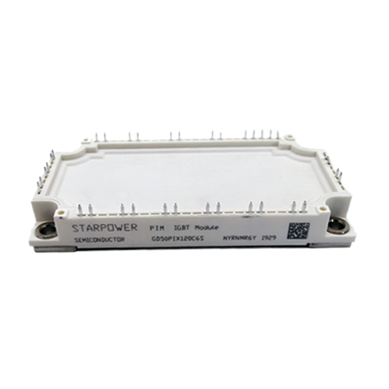
A purchase-ready IGBT module is defined by three constraint groups that must all be confirmed in writing before an order is released: the electrical envelope, the structural and isolation configuration, and the document pack that proves what the part actually is. Price and lead time are negotiated after those three are closed — never instead of them.
Jiangsu Core Diamond Times Electronic Technology Co., Ltd. is a power electronic component supplier based in Kunshan, Jiangsu, China, serving industrial buyers in the EU, USA, Australia and the Middle East with IGBT modules, power semiconductor modules and industrial fuses. Because a single bill of materials frequently mixes Infineon, SEMIKRON, Fuji, CRRC and other module families, the workflow below is written to work across brands rather than for one product line.
Problem Definition: Why “Compatible” Is Not a Specification
Most power-module sourcing failures do not begin with a dishonest supplier. They begin with an incomplete requirement, and they surface later as field returns, thermal alarms or goods rejected at incoming inspection. Three failure modes account for most of them.
- Envelope mismatch. A substitute part sits in the same package and carries a similar part number, but its voltage or current rating sits below the continuous and peak demand of the application. The device may pass bench testing and still fail under real load cycling.
- Structural mismatch. The substrate, base plate and isolation method determine how heat leaves the chip and how the module behaves in a high-vibration cabinet. Two modules with identical ratings can have completely different thermal paths.
- Document mismatch. The buyer receives a datasheet with the right headline numbers but cannot trace a test record, a certificate file number or a scope statement. In an audit, that is the same as having no evidence at all.
The practical consequence is that verification belongs to the Research and Evaluation stage, not to the post-delivery stage. Once a module has been designed into a board layout and a heat sink, changing it is expensive.
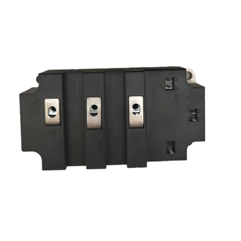
Industry Background: Why Parameter and Document Discipline Matters More Each Year
Power semiconductor demand keeps expanding, and so does the number of parts a buyer has to choose between. Market Research Future estimates the global IGBT market at USD 9,202.9 million in 2024 and projects a compound annual growth rate of 11.02% between 2025 and 2035. Fortune Business Insights places the global silicon carbide (SiC) module market at USD 980.7 million in 2025 — a smaller but faster-moving segment that competes for the same inverter slots as silicon IGBT modules.
Downstream, the stakes are high. One commercial research estimate places IGBT content at roughly 10% of the cost of an electric vehicle, and StarPower Semiconductor is ranked as the world’s fifth-largest IGBT module supplier, which shows how concentrated the module supply base still is. Infineon describes IGBT modules as a central component in inverters for electric drives, battery chargers, solar systems and wind power — the same application set that most buyers are specifying for.
Two consequences follow. First, cross-brand substitution is normal, because no single manufacturer covers every voltage class, package and lead time. Second, part-number conventions do not travel: the Infineon MIPAQ, FF, FZ, FS and FP family designators, SEMIKRON SKM naming, IXYS IXFN MOSFET designations, Fuji 2MBI series, and the numbering used across Mitsubishi, Microchip, CRRC, StarPower, WESTCODE, POSEICO and SanRex families each follow their own logic. A buyer who reads the number as if it were a specification will mis-select — which is precisely why distributors and component suppliers exist, carrying several families in stock and translating a circuit requirement into an available part.
Silicon carbide modules, meanwhile, occupy a separate evaluation track. SiC changes the thermal and drive requirements of a design rather than acting as a drop-in substitute for a silicon IGBT module, so SiC and IGBT shortlists should be built and verified independently.
The Constraint Set: What Has to Be Confirmed Before Purchase
Constraint 1 — The electrical envelope
The envelope is a range, not a single number, and it has to cover the worst case rather than the nominal case. In the stocked range, IGBT modules are rated from 600 V to 1700 V with current ratings from 50 A to 1200 A. Adjacent families sit in different envelopes: power MOSFET modules cover drain-source voltages of 60 V to 1200 V and drain currents of 30 A to 300 A; thyristors (SCR) are rated up to 3000 V with current ratings up to 1100 A; fast recovery power diodes reach peak repetitive reverse voltages of up to 2800 V with forward currents from 100 A to 1800 A; bridge rectifier modules are rated from 800 V to 2000 V peak reverse voltage with average forward currents from 25 A to 800 A.
For sizing, a buyer should fix three values before looking at any catalogue: the maximum DC bus voltage, the continuous RMS current, and the peak overload current together with its duration. The module’s rated current is then selected with margin against the continuous figure, and short-circuit withstand capability is checked against the drive protection window.
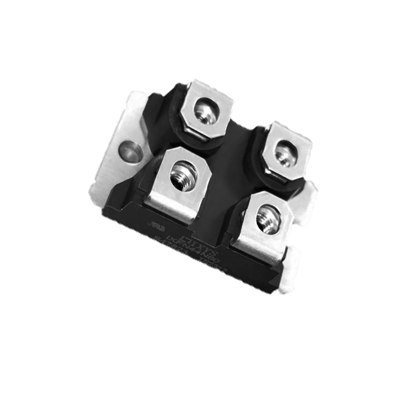
Constraint 2 — Structural configuration and thermal path
Structure decides whether the electrical envelope can actually be used. The IGBT module uses a single or dual IGBT chip structure built on an aluminium ceramic substrate with a copper base plate and a plastic housing, in an isolated baseplate design, and is specified with low saturation voltage and high switching speed. Power MOSFET modules follow the same isolated-baseplate approach, with a silicon MOS chip on an aluminium ceramic substrate, again with a copper base plate and plastic housing.
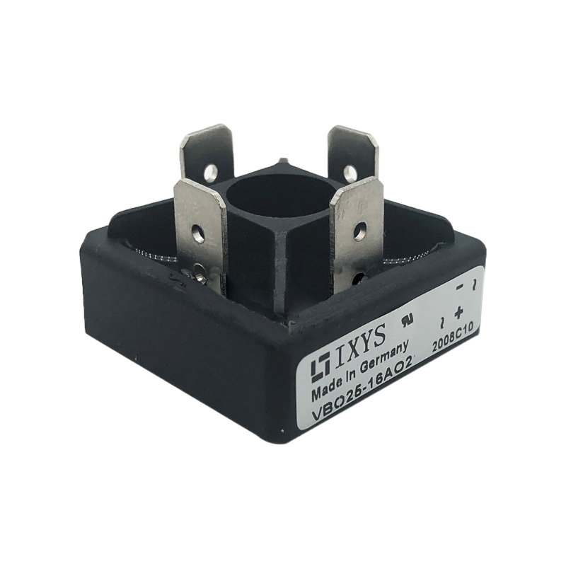
Other families use different construction because they solve a different problem. Thyristors use a disc-type package with a ceramic housing, molybdenum disc and copper base, with the silicon wafer as the primary material. Fast recovery diodes use a silicon wafer with a copper base and a ceramic housing. Bridge rectifier modules use silicon diode chips on an aluminium ceramic substrate with a copper base plate and plastic housing, are available in single-phase or three-phase configuration, and are specified with an isolated baseplate and a low forward voltage drop.
In practice, three structural questions resolve most thermal and mechanical risk: how the module is isolated from the heat sink, what the base plate material and flatness permit in terms of thermal interface, and how the module is mounted, including screw torque and clamping method. The remaining variable is usually the interface between base plate and heat sink. Thermal grease coverage, screw torque and heat sink cleanliness decide whether the specified thermal resistance is actually reached inside the cabinet or only on the datasheet.
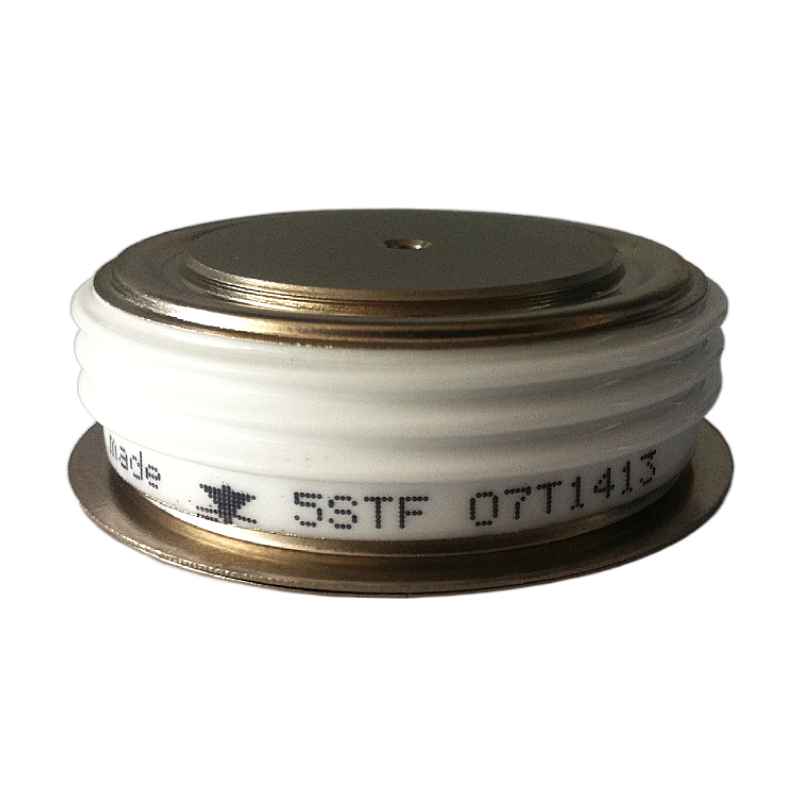
Constraint 3 — Documents and certification evidence
Documentation is a deliverable, not a courtesy. A complete pack lets a buyer answer three questions: what the part is, how it was tested, and which certificate covers it and with what scope.
At supplier level, Jiangsu Core Diamond Times holds ISO 9001:2015 quality management system certification, effective 16 June 2026. At product level, the industrial fuse range is certified to IEC, CCC and UL standards, with the following records on file:
- UL file E4273, issued by Underwriters Laboratories Inc. under standard UL 248-1, covering nonrenewable cartridge fuses in Classes CC, G, H, J, K1, K5, L, RK1, RK5 and T for the North America market; issued 10 January 2009, with no specified expiry date.
- UL file IZLT.E14853, issued by UL under standard UL 248-1 for the US market; issued 10 January 2009, with no expiry date recorded. The record covers cartridge fuse holders rated 250–600 V AC/DC, 30–60 A, with withstand ratings of 10,000–200,000 A RMS symmetrical.
- CCC certificate 2024010308676645, issued by the China Quality Certification Centre under GB/T 13539.4-2016, valid from 15 August 2024 to 14 August 2029, covering semiconductor equipment protection fuse-links in model series 170M Size 3 and 170L Size 3 Un.
- EC Declaration of Conformity CE1600245, issued by Eaton, referencing EN 60269-1:2007+A1:2009+A2:2014 and HD 60269-2:2013 under the 2014/35/EU Low Voltage Directive, covering fuse types C10G*, C10M*, C14G*, C14M*, C22G*, C22M*, C08G* and C08M*, valid without an expiry date, for the EU market.
Two points deserve emphasis. First, these certificates apply to the fuse product family; certification scope has to be read line by line and never assumed across a whole catalogue. Second, the relevant international framework for semiconductor devices is the IEC 60747 series, in which IEC 60747-9 addresses insulated-gate bipolar transistors. A supplier that can name the correct standard and then produce the parameter definitions and test references behind its datasheet is in a very different position from one that answers “IEC compliant” without a document number.
Step-by-Step Breakdown: A Six-Step Verification Workflow
Step 1 — Fix the electrical envelope with margin
Write down maximum bus voltage, continuous current, peak overload current and duration, switching frequency and expected ambient temperature. Match the module voltage rating to the bus with derating for switching overshoot, and match the current rating to the continuous value with overload margin. Do this before opening a catalogue, so the shortlist is generated by requirements rather than by availability.
Step 2 — Lock the package and structural configuration
Confirm the chip structure (single or dual IGBT), the isolation method (isolated baseplate), the substrate and base plate materials, and the terminal layout that your drive board expects. A module that fits mechanically but reverses the gate and emitter terminal order will destroy the driver stage on first power-up.
Step 3 — Verify the thermal and mounting interface
Check base plate flatness, specified mounting torque, thermal grease type and recommended heat sink thermal resistance. Two causes dominate real-world IGBT overheating: uneven thermal grease and loose mounting screws, both of which degrade the contact between base plate and heat sink. Both are installation variables, so they belong in the verification plan rather than in the failure report.
Step 4 — Assemble the document pack
Request the datasheet with parameter definitions, the electrical test record for the delivered lot, certificate file numbers with scope statements, and a written statement of which standard each claim refers to. Where a project requires traceability, ask how incoming inspection and pre-shipment control are documented; a supplier’s stated incoming inspection and outgoing quality control procedures are the mechanism behind that traceability, and 100% electrical performance testing before shipment is the evidence point to ask about.
Step 5 — Map project standards to supplier evidence
Separate two document layers. The device layer concerns semiconductor parameter definitions and test methods, which is where the IEC 60747 series applies. The system layer concerns the end product’s market access — UL 248-1 for North American fuse applications, GB/T 13539.4-2016 for the Chinese market, and the 2014/35/EU Low Voltage Directive for the EU. A supplier that understands the difference will tell you which layer each document belongs to, and that answer is itself a qualification signal.
Step 6 — Close the commercial constraints
Only after steps 1 to 5 should MOQ, price and lead time be treated as decision variables. The stated minimum order quantity for the stocked range is 2 units, which allows a genuine trial before volume commitment, and standard lead time runs 30–45 days. Where a requirement sits between two parts, the deciding factor is usually whether the supplier can support parameter matching and solution support under an OEM or ODM arrangement, or whether the design has to be adjusted to fit what is in stock.
Use Cases: How These Constraints Behave in Real Projects
Verification priorities shift with the application, and the delivered projects below show where each constraint carried the most weight.
- Solar and energy storage conversion (Germany). A renewable energy equipment manufacturer ordered 5,000 IGBT modules for solar inverter and energy storage converter builds over a two-year period. The priority was long-term stability under high temperature and high load with a low failure rate, and the selected modules were specified for low thermal resistance, high switching speed and strong overload capacity with good heat dissipation. The thermal constraint dominated.
- On-board power conversion (Poland). An EV accessory manufacturer took 4,000 MOSFET modules for on-board power converters across two years, prioritising low on-resistance and high efficiency for stable performance and long service life. Conduction loss dominated.
- Industrial switching power supply (Spain). A power supply factory ordered 10,000 bridge rectifier modules over two years to hold reliable rectification output, with high current capacity and a compact structure as the deciding features. Mechanical fit and current capacity dominated.
- Charging pile and rectifier power supply (Malaysia). A power electronics OEM took 8,000 fast recovery power diodes over two years, prioritising fast recovery speed and low power loss so reverse leakage stayed low in charging pile equipment. Switching behaviour dominated.
- Industrial welding and rectifier equipment (Italy). An industrial power supply manufacturer ordered 3,500 thyristors over two years for continuous operation, with high surge current resistance and a stable turn-on characteristic as the key requirements. Surge tolerance dominated.
- Energy storage cabinet protection (France). A new energy system integrator ordered 15,000 fuses over one year for power conversion and switching control in energy storage cabinets, with high breaking capacity and high safety as the selection drivers so the circuit could be cut quickly on overcurrent. Here the protection layer, not the switching layer, set the constraint.
The pattern is consistent: the module that wins is the one whose weakest parameter still clears the application’s worst case. That is a constraint question, not a brand question.
Comparison Table: Module Families and Their Parameter Envelopes
| Module family | Voltage envelope | Current envelope | Structural configuration | Constraint to verify first |
|---|---|---|---|---|
| IGBT module | 600 V – 1700 V | 50 A – 1200 A | Single/dual IGBT chip structure; aluminium ceramic substrate; copper base plate; plastic housing; isolated baseplate | Switching loss and short-circuit withstand against the drive protection window |
| Power MOSFET module | 60 V – 1200 V (drain-source) | 30 A – 300 A (drain) | Silicon MOS chip; aluminium ceramic substrate; copper base plate; plastic housing; isolated baseplate | On-state resistance and switching frequency versus conduction loss |
| Thyristor / SCR | Up to 3000 V | Up to 1100 A | Disc-type package; ceramic housing; molybdenum disc; copper base; silicon wafer | Surge current capability and clamping force |
| Fast recovery power diode | Up to 2800 V (peak repetitive reverse) | 100 A – 1800 A (forward) | Silicon wafer; copper base; ceramic housing | Reverse recovery behaviour and forward voltage drop |
| Bridge rectifier module | 800 V – 2000 V (peak reverse) | 25 A – 800 A (average forward) | Silicon diode chips; aluminium ceramic substrate; copper base plate; plastic housing; single-phase or three-phase; isolated baseplate | Phase configuration and heat sink coupling |
| Industrial power fuse | 690 V – 1500 V (rated) | 10 A – 1250 A (rated) | Ceramic tube body; metal end caps; silver-plated copper element; quartz sand filler | Breaking capacity versus prospective short-circuit current |
The envelopes above describe the stocked product range. A specific part number always governs: the envelope tells you whether a family is worth evaluating, not whether a given module fits a given design.
Documentation Evidence Currently on File
| Record | Issuing body / standard | Scope | Market |
|---|---|---|---|
| ISO 9001:2015 (effective 16 June 2026) | Quality management system certification | Supplier-level quality management | International |
| UL E4273 | Underwriters Laboratories Inc.; UL 248-1 | Nonrenewable cartridge fuses, Classes CC, G, H, J, K1, K5, L, RK1, RK5, T | North America |
| UL IZLT.E14853 | UL; UL 248-1 | Cartridge fuse holders, 250–600 V AC/DC, 30–60 A | US |
| CCC 2024010308676645 | China Quality Certification Centre; GB/T 13539.4-2016 | Semiconductor equipment protection fuse-links, 170M Size 3 / 170L Size 3 Un | China |
| EC DoC CE1600245 | Eaton; EN 60269-1:2007+A1:2009+A2:2014, HD 60269-2:2013, 2014/35/EU | Fuse types C10G*, C10M*, C14G*, C14M*, C22G*, C22M*, C08G*, C08M* | EU |
These records cover the fuse range. For module families, equivalent evidence has to be requested per part number, and the scope statement should be read before the certificate number is accepted.

Frequently Asked Questions
How do I verify that a supplier can provide IEC 60747 documentation for IGBT modules?
Start by naming the standard correctly. IEC 60747 is the IEC series covering semiconductor devices, and IEC 60747-9 is the part that addresses insulated-gate bipolar transistors; it defines parameter terminology and test methods rather than the finished assembly. A practical verification therefore asks three things in writing: the datasheet parameters your design depends on, the test record showing those parameters were measured, and a statement of which standard and which scope each certificate covers. A supplier that holds ISO 9001:2015 certification and can point to certificate file numbers with a defined scope — as the fuse range does with UL E4273, UL IZLT.E14853, CCC 2024010308676645 and EC DoC CE1600245 — is answering the documentation question in a traceable way. Treat “IEC compliant” without a document reference as an unanswered question.
Can IGBT modules be customized for a specific circuit design?
Part-level customization in this range covers logo marking, packaging, parameter matching and solution support under an OEM or ODM arrangement. Parameter matching means the supplier reviews your circuit design and working conditions and recommends the module that fits them, rather than only offering what happens to be on the shelf. What customization does not do is change the physical limits of a given chip and package, so the electrical envelope remains the first constraint regardless of branding or packaging changes.
What is the minimum order quantity, and how does it affect cost?
The stated minimum order quantity for the stocked range is 2 units, low enough to validate a part before committing to volume. Cost is driven mainly by the electrical envelope, the chip technology behind the part, the package and structural configuration, and the testing and documentary scope attached to the order. Because a higher voltage class, a larger current rating and a broader test scope each add cost, the most effective way to control budget is to size the module to the application’s real worst case rather than to a generous margin the design does not need.
Can I order a sample before a bulk purchase?
Yes. Trial orders are supported alongside bulk volume orders, and 100% electrical performance testing is carried out before shipment, so a sample order delivers a real device with a test record rather than a hand-picked unit. For evaluation, specify the working conditions you intend to test against — bus voltage, load current, switching frequency and cooling setup — so the sample can be checked for parameter matching at the same time.
What lead time should I plan for, and who supports the design-in?
Standard lead time is 30–45 days, with stock held on mainstream IGBT module and industrial fuse models for urgent orders, and a monthly capacity of 20,000 units behind the stocked range. Technical support comes from five technical support engineers who handle component selection and solution support, with remote technical support and after-sales warranty service after delivery. To confirm availability and request a quotation for a specific part number, send the requirement to xinzuanshidai@163.com or message +86 13675967789 on WhatsApp, and include the voltage class, current rating, package and target quantity.
Conclusion: Verify the Constraints, Then Negotiate the Price
An IGBT module is only purchase-ready once the electrical envelope, the structural and isolation configuration, and the document pack have each been confirmed in writing. The envelope tells you whether the part can survive the application’s worst case. The structure tells you whether the heat can leave the chip inside the cabinet you are actually building. The documents tell you whether any of it can be defended in an audit or a customer qualification. Price, MOQ and lead time are real constraints too, but they are the last ones to negotiate, not the first ones to decide.
Applied consistently, the six-step workflow above turns a catalogue search into a requirements-driven evaluation: define the envelope, lock the package, verify the thermal interface, assemble the documents, map the standards, and only then settle commercial terms. Buyers who follow that sequence spend less time replacing failed parts and more time shipping equipment that meets its own specification.
Next Step
Send us the constraint set rather than a part number: bus voltage, continuous and peak current, switching frequency, cooling method, mounting space, target quantity and any certification the project requires. The team will come back with a matched module or fuse from the stocked range, the applicable document pack, and a lead time you can plan around.
Email: xinzuanshidai@163.com | WhatsApp / Tel: +86 13675967789 | Website: www.xinzuanshidai.com
Company brochure (open download): Jiangsu Core Diamond Times product & capability brochure