
IGBT Module vs MOSFET Module: A Comparison Guide for Industrial Power Design

Incoming and outgoing inspection: the step that decides whether a module matches the datasheet it was designed against.
Choosing between an IGBT module and a MOSFET module is a voltage-and-frequency decision before it becomes a price decision. MOSFET modules cover drain-source voltages from 60 V to 1200 V and drain currents from 30 A to 300 A, and they are selected when low on-state resistance and high switching frequency dominate the loss budget. IGBT modules cover 600 V to 1700 V and 50 A to 1200 A, and they are selected when low saturation voltage, high current capability and strong overload behaviour matter more than switching speed.
That rule of thumb is enough to sketch a first block diagram, but it is not enough to release a design. By the time a converter reaches prototyping, the module choice has already fixed the gate driver, the heat sink interface, the isolation distance and the certification file. Switching devices later means repeating thermal validation, switching-loss measurements and compliance documentation. The comparison below therefore covers both halves of the decision: matching the device to the electrical duty, and verifying that the part delivered matches the device you designed against.
What problem does this comparison solve?
Power semiconductor decisions usually fail in one of two places. The first is technical: the device is undersized for the real current profile, or the switching frequency is set higher than the chosen technology can support efficiently. The second is commercial: the module is technically correct, but the sourcing path introduces counterfeit parts, undocumented parameter deviations, or a supply gap during ramp-up.
For IGBT modules specifically, the documented risks during procurement and application are electrical overstress, thermal runaway, aging and reliability degradation, counterfeit parts and supply shortage. These risks are triggered by insufficient heat dissipation, overvoltage or overcurrent impact, sourcing from unqualified suppliers, and supply shortage caused by market fluctuation. The standard mitigations are derating design combined with a reliable thermal solution, supplier qualification with incoming inspection, and a qualified alternative supplier pool.
A MOSFET module carries a different risk profile: because it is typically used at lower voltage and higher switching frequency, the critical failure modes concentrate on gate drive integrity, switching noise and thermal design at high frequency rather than on short-circuit ruggedness. Comparing the two technologies on the same five parameters makes both risk profiles visible before the purchase order stage.
Industry background: where the two technologies sit in 2026
IGBT technology remains a large and still-growing category. Market Research Future estimates the global IGBT market at USD 9,202.9 million for 2024 and projects a compound annual growth rate of 11.02% from 2025 to 2035. Fortune Business Insights values the global silicon carbide (SiC) module market at USD 980.7 million in 2025 — a smaller but technically important adjacent category for high-efficiency, high-frequency designs. The same market research notes that IGBT devices account for nearly 10% of the cost of an electric vehicle, which is why module selection is treated as a cost-critical decision in EV and charging projects rather than a purely engineering detail.
Demand comes from both sides of the comparison. Infineon states that IGBT modules are a central component in inverters for electric drives, battery chargers, solar systems and wind power applications. MOSFET modules in our supply range are specified for high-frequency inverters, chargers and switching power supplies, with documented industries including new energy vehicle chargers, switching power supplies, solar inverters, industrial power supplies and battery management systems. Solar inverters, chargers and industrial power supplies appear on both lists, which is exactly why the choice has to be made on parameters rather than on application names alone.
On the supply side, sourcing conversations in this category typically involve brand families such as Infineon, SEMIKRON, IXYS, Microsemi, Fuji, SanRex, Mitsubishi, IR, CRRC, StarPower, WESTCODE, POSEICO and Microchip modules. Market Research Future ranks StarPower Semiconductor as the world's fifth-largest IGBT module supplier. Infineon's own part-number designator defines module families such as FF (dual switch), FZ (single switch), FS (three-phase full bridge), FP (power integrated) and MIPAQ — a naming convention worth knowing when checking whether a quoted part is genuinely an equivalent of the part in your design file.
Jiangsu core diamond times Electronic Technology Co., Ltd. is a Kunshan-based supplier of power electronic components, founded in 2022, with supply channels that include Infineon, SEMIKRON, Fuji and CRRC modules alongside IGBT modules, MOSFET modules, thyristors, power diodes, bridge rectifier modules and industrial fuses. Its quality management system is certified to ISO9001:2015, effective 16 June 2026.
Detailed comparison: where IGBT and MOSFET modules diverge
1. Voltage and current class
The clearest dividing line is the rated voltage window. A power MOSFET module in our range is specified from 60 V to 1200 V drain-source voltage with 30 A to 300 A drain current. An IGBT module in the same supply range is specified from 600 V to 1700 V with 50 A to 1200 A current rating. The two technologies therefore overlap between 600 V and 1200 V, and that overlap is where most design arguments happen. Above roughly 1200 V, the IGBT module is the only option of the two. At low bus voltages, the MOSFET module is normally the simpler and more efficient choice.
2. Conduction behaviour: on-state resistance versus saturation voltage
The MOSFET module is characterised by low on-state resistance. Conduction loss in a MOSFET therefore rises with the square of current, which means the penalty for high continuous current grows quickly. The IGBT module is characterised by low saturation voltage, a comparatively flat conduction characteristic that stays favourable as current increases into the hundreds of amperes. The practical decision rule: where continuous current is high and the bus voltage is high, IGBT conduction behaviour is usually the better fit; where current is moderate and switching is fast, low on-resistance is the stronger advantage.
3. Switching frequency and switching loss
Switching behaviour is where the two devices separate most sharply in practice. MOSFET modules are specified for high switching frequency and are the natural choice for high-frequency inverters, chargers and switching power supplies. IGBT modules are specified as high switching speed, but switching loss occurs during turn-on and turn-off, in the short interval where voltage and current overlap. That loss increases as switching frequency rises, which sets a practical frequency ceiling for IGBT modules in any given design. Increasing switching frequency without re-checking the loss budget is one of the most common causes of unexpected temperature rise in an IGBT-based converter.
Inside an IGBT module, the freewheeling diode matters as much as the switch. It provides a freewheeling path for inductive current during turn-off and suppresses voltage spikes to protect the chip, so reverse recovery behaviour of the internal diode belongs on the parameter checklist, not only the IGBT rating.
4. Isolation, substrate and thermal path
Both module types in our range share the same construction logic: an isolated baseplate, an aluminium ceramic substrate, a copper base plate and a plastic housing. The MOSFET module uses silicon MOS chips; the IGBT module uses silicon chips in a single or dual IGBT chip structure. That shared construction means the thermal path is engineered the same way for both — and so are the failure modes. Documented causes of IGBT module overheating are insufficient heat dissipation, unevenly applied thermal grease, loose mounting screws with poor baseplate-to-heat-sink contact, operating current above the module rating, a dust-blocked radiator, and an abnormal gate drive signal generating extra loss.
5. Where each module is specified to work
MOSFET modules are documented for high-frequency inverters, chargers and switching power supplies, and for new energy vehicle chargers, solar inverters, industrial power supplies and battery management systems. IGBT modules are documented for power inverters, UPS, welding machines, new energy power conversion and motor drives, across new energy, power supply, industrial automation, welding equipment, electric motor drive and UPS industries. The overlap is real but narrow; where an application appears on both lists, the deciding parameters are current level, switching frequency and thermal budget rather than the application label.
Comparison table: IGBT module vs MOSFET module
| Comparison dimension | MOSFET module | IGBT module |
|---|---|---|
| Chip and structure | Silicon MOS chip; isolated baseplate | Silicon chip; single or dual IGBT chip structure; isolated baseplate |
| Voltage range | Drain-source voltage 60 V – 1200 V | 600 V – 1700 V |
| Current range | Drain current 30 A – 300 A | 50 A – 1200 A |
| Conduction characteristic | Low on-state resistance | Low saturation voltage |
| Switching characteristic | High switching frequency | High switching speed; switching loss increases with switching frequency |
| Typical circuit use | High-frequency inverter, charger, switching power supply | Power inverter, UPS, welding machine, new energy power conversion, motor drive |
| Documented industries | New energy vehicle charger, switching power supply, solar inverter, industrial power supply, battery management system | New energy, power supply, industrial automation, welding equipment, electric motor drive, UPS |
| Package materials | Aluminium ceramic substrate, copper base plate, plastic housing | Aluminium ceramic substrate, copper base plate, plastic housing |
Table 1. Parameter-level comparison based on the module specifications in our supply range.
Step-by-step: selecting the right module for an industrial project
The sequence below follows the order in which decisions actually become irreversible. Working through it in order prevents the common situation where a module is chosen on voltage alone and the thermal or compliance work is discovered later.
- Step 1 — Fix the voltage and current duty. Define the DC bus voltage, the continuous working current and the peak overload current. Industrial-grade selection normally applies a derating margin of around 1.5 times on both voltage and current, so that surge load is absorbed without shortening module life.
- Step 2 — Set the switching frequency and the loss budget. If the design must switch fast, the MOSFET module is the natural starting point. If the design uses an IGBT module, calculate switching loss at the intended frequency before fixing the heat sink, because switching loss grows as frequency rises.
- Step 3 — Apply the conduction criterion. Compare expected continuous current against the trade-off between low on-state resistance (MOSFET) and low saturation voltage (IGBT). High continuous current at high bus voltage usually points to the IGBT module.
- Step 4 — Confirm package, isolation and thermal interface. Check heat sink structure and mounting space, confirm the isolated baseplate rating, and plan thermal grease thickness and screw tightening torque according to the module datasheet rather than workshop habit.
- Step 5 — Verify pin definition and gate drive compatibility. Compare the module pin definition against the existing drive board. Pin or gate-loop mismatch is a frequent reason a technically correct module cannot be dropped in without a board revision.
- Step 6 — Confirm parameters, certification and delivery terms. Rated current, rated voltage, package type, junction temperature range, switching frequency, short-circuit withstand time and insulation class must all be confirmed in writing, together with reliability grade, certification evidence, delivery lead time, supplier capacity, warranty and acceptance criteria.
- Step 7 — Validate by sample, then secure continuity. Run a sample through electrical and thermal verification before committing to volume, and keep an approved second source for the same parameter set.
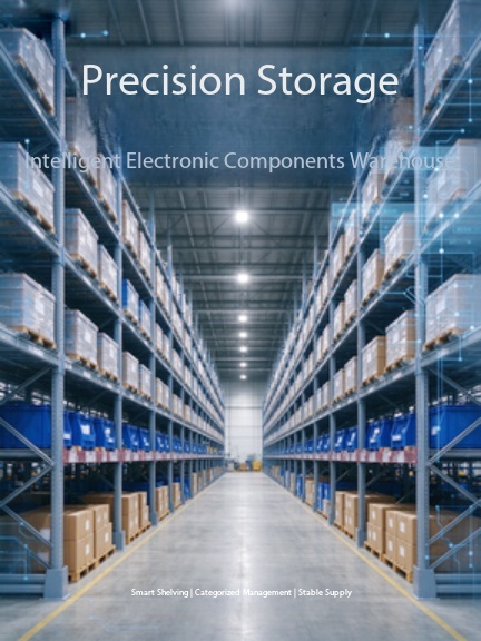
Storage discipline matters as much as selection: unused modules are held in original anti-static packaging at -10 °C to +40 °C and relative humidity no higher than 70%, away from dust, corrosive gas and static fields.
Procurement risks, parameter confirmation and certification for IGBT modules
Procurement and application risks
The risk register below is the one buyers should carry into supplier evaluation for IGBT modules in industrial inverter projects. It is deliberately short, because these are the risks that actually interrupt production.
| Risk | Documented trigger | Mitigation |
|---|---|---|
| Thermal runaway | Insufficient heat dissipation; operating current above the module rating | Derating design plus a reliable thermal solution; verify thermal grease application and screw torque |
| Electrical overstress | Overvoltage or overcurrent impact | Voltage and current derating margin; verify gate drive waveform |
| Aging and reliability degradation | Excessive junction temperature; power cycling fatigue | Industrial-grade modules; periodic inspection; replace the module once failure occurs |
| Counterfeit parts | Sourcing from unqualified suppliers | Supplier qualification audit; incoming inspection; verify product certificates before procurement |
| Supply shortage | Supply shortage caused by market fluctuation | Maintain a qualified alternative supplier pool and stock planning for mainstream models |
Table 2. Procurement and application risks for IGBT modules, with the documented mitigations.
Parameters to confirm before a purchase order is released
Parameter confirmation is a written exercise. For IGBT modules the confirmation list covers rated current, rated voltage, package type, junction temperature range, switching frequency, short-circuit withstand time and insulation class. Alongside the electrical set, confirm reliability grade, certification, delivery lead time, supplier capacity, warranty terms and acceptance criteria. Short-circuit withstand time deserves specific attention: it is the maximum time the device can sustain short-circuit current under specified test conditions before failure, and a longer withstand time gives the protection circuit more room to react.
Certification and compliance evidence
For industrial inverter applications, IGBT modules are normally expected to carry UL, IEC 60747 (semiconductor device standard), RoHS and REACH compliance. Where the end equipment has a functional safety requirement, IEC 61508 SIL certification may also be required. The evidence pack should include test reports and declaration documents, not only a certificate image — UL covers insulation and thermal reliability, IEC 60747 covers the semiconductor device test specification, RoHS and REACH cover restricted hazardous substances, and IEC 61508 requires a documented SIL assessment.
| Requirement | What it covers |
|---|---|
| UL | Safety certification for insulation and thermal reliability |
| IEC 60747 | Semiconductor device test specification |
| RoHS and REACH | Restriction of hazardous substances in the delivered product |
| IEC 61508 (SIL) | Functional safety assessment, with complete test reports and declaration documents |
Table 3. Compliance evidence typically requested for IGBT modules in industrial inverter projects.
Protection coordination and documentation checks
Module protection is only as good as the overcurrent device in front of it. Protection components should be selected according to the actual working current and the short-circuit breaking requirement of the circuit, and product certificates should be verified before procurement rather than after. The classic protection failures are documented: an improperly selected current rating leads to delayed protection or unnecessary blowing, exceeding the rated breaking capacity of a protection device creates an explosion hazard, high ambient temperature shortens protective device life, and uncertified counterfeit products carry undefined breaking behaviour — any of which can turn a module-level fault into a safety incident.

Assembly and OEM/ODM support: module projects with logo marking, packaging or parameter-matching requirements are handled through documented production service modes.
Use cases: how buyers applied IGBT and MOSFET modules
The cases below show how the parameter logic translates into delivered projects. Each entry reflects an actual supply relationship and the working condition it had to survive.
- Solar inverter and energy storage converter (Germany). A renewable energy equipment manufacturer ordered 5,000 IGBT modules over a two-year project for solar inverter and energy storage converter builds. The requirement was long-term stable operation under high temperature and high load with low failure rate, meeting European energy storage system standards. The selected modules were chosen for low thermal resistance, high switching speed, strong overload capacity and good heat dissipation performance.
- On-board power converter (Poland). An EV accessory manufacturer ordered 4,000 MOSFET modules over two years for an on-board power converter. The result was stable performance in a vehicle-mounted converter with long service life; the selection criteria were low on-resistance and high efficiency — the classic MOSFET advantages in a high-frequency, moderate-current application.
- Industrial switching power supply (Spain). A power supply factory ordered 10,000 bridge rectifier modules over two years for industrial switching power supply builds, achieving reliable rectification output with high current capacity in a compact structure.
- Adjacent cases. A power electronics OEM in Malaysia ordered 8,000 fast recovery power diodes for charging pile and rectifier power supplies, noted for fast recovery speed and low power loss; an industrial power supply manufacturer in Italy ordered 3,500 thyristors for welding and power rectifier equipment, noted for high surge current resistance and stable turn-on characteristics.
When a project does not sit cleanly inside the IGBT-versus-MOSFET decision, the adjacent module families usually explain why. They are worth checking before assuming an IGBT or MOSFET module is required.
| Module family | Voltage / current | Where it fits |
|---|---|---|
| Power diode | Peak repetitive reverse voltage up to 2800 V; forward current 100 A – 1800 A | Rectification, welding equipment, industrial power supply, charging pile rectifier stages |
| Thyristor / SCR | Voltage rating up to 3000 V; current rating up to 1100 A | Industrial power control, metallurgy, welding power supply, motor soft starter |
| Bridge rectifier module | Peak reverse voltage 800 V – 2000 V; average forward current 25 A – 800 A | AC-DC conversion in power supplies, welding machines, motor control and new energy equipment |
Table 4. Adjacent power module families and their documented voltage, current and application ranges.
FAQ: IGBT and MOSFET module selection questions
Which certifications should be confirmed before an IGBT module is approved for an industrial inverter?
IGBT modules used in industrial inverters are normally expected to comply with UL, IEC 60747 for semiconductor device testing, and RoHS and REACH for restricted substances. Where the end equipment carries a functional safety requirement, IEC 61508 SIL certification may also be required. Beyond the certificate itself, request the test report and declaration documents, and confirm that the certificate scope covers the exact product family and model being purchased, because a certificate issued for a different series does not validate the part on your bill of materials.
Chinese IGBT module OEM manufacturers with custom voltage ratings — what should buyers actually verify?
Buyers should separate parameter matching from a new voltage class. IGBT modules in our supply range cover 600 V to 1700 V and 50 A to 1200 A, and customization services cover logo marking, packaging, parameter matching and solution support — that is parameter matching to your circuit conditions, not the creation of an arbitrary new voltage rating. Practically, verify three things: the datasheet values for the exact model quoted, pin definition compatibility with your existing drive board, and whether the supplier operates documented OEM and ODM service modes at all. A sample order and a written parameter confirmation are the cheapest way to close that gap before volume commitment.
What drives the cost difference between an IGBT module design and a MOSFET module design?
Cost in this category is driven by voltage and current class, package and isolation construction, the thermal solution required by the loss budget, the switching frequency the design runs at, and the certification or functional safety evidence required by the end market. Two effects push in opposite directions: a MOSFET module avoids IGBT switching-loss penalties at high frequency, while an IGBT module handles high continuous current with a flatter conduction characteristic that can reduce the number of paralleled devices. Where a project requires high efficiency at high frequency, SiC hybrid modules are available with superior thermal performance at a premium price — a cost line worth evaluating only where efficiency targets justify it.
How should a buyer validate a power module before placing a volume order?
Validation starts with a sample. Confirm the ratings against the circuit conditions, then test the gate drive waveform and inspect for abnormal signals that would generate extra loss. Thermal verification comes next: clean the heat sink and baseplate, apply thermal grease evenly at the correct thickness, fasten screws in diagonal sequence to the specified torque, and run a no-load test while monitoring temperature rise. Confirm that the supplier performs a 100% electrical performance test before shipment, and store unused modules in original anti-static packaging at -10 °C to +40 °C with relative humidity no higher than 70%, away from dust, corrosive gas and static fields.
What lead time and supply continuity should be planned for module orders?
Supply planning should assume that market fluctuation can interrupt a single source, since supply shortage from market fluctuation is a documented risk in this category. The practical buffer is a qualified alternative supplier pool plus stock planning for mainstream models. At Jiangsu core diamond times Electronic Technology Co., Ltd., standard production lead time runs 30 to 45 days against a monthly capacity of 20,000 units, trial orders are accepted from a minimum of 2 units, and remote technical support plus after-sales warranty service are provided after delivery. Buyers who need to validate a module before committing to a project volume can start with a sample request or a quotation for the exact model list.
Conclusion: a decision rule you can hand to the design team
Use a MOSFET module when the bus voltage sits at the lower end of the 60 V to 1200 V range, when continuous current stays inside the 30 A to 300 A window, and when high switching frequency with low on-state resistance is the dominant design objective — new energy vehicle chargers, switching power supplies and solar inverter stages all fit this profile. Use an IGBT module when voltage runs from 600 V to 1700 V, current from 50 A to 1200 A, and low saturation voltage with strong overload capability matters more than switching speed — power inverters, UPS, welding machines, motor drives and new energy power conversion fit this profile.
Whichever device the design selects, the risk work is the same: confirm the full parameter list in writing, apply a derating margin of around 1.5 times on voltage and current, secure the certification and test documentation for the exact model, validate with a sample under real thermal conditions, and keep an approved second source for continuity. That combination is what keeps a technically sound module choice from becoming a production problem.

Stock holding for mainstream module models, planned against the 30 to 45 day production lead time.
Next step: sample, quotation or catalogue
Send your circuit conditions — bus voltage, continuous and peak current, switching frequency and drive board pin definition — and we will confirm the matching IGBT module or MOSFET module model, its certification evidence and the quotation. Trial orders start from 2 units, with OEM and ODM service modes available for logo marking, packaging, parameter matching and solution support.
Jiangsu core diamond times Electronic Technology Co., Ltd.
Website: www.xinzuanshidai.com
Email: xinzuanshidai@163.com
Tel / WhatsApp: +86 13675967789
Address: Room A201, North Building, Yifeng Electromechanical City, Development Zone, Kunshan City, Jiangsu Province, P.R. China
Download the product catalogue: Jiangsu core diamond times product brochure (PDF)

Outbound logistics for export orders to the EU, Southeast Asia, Middle East and South America.
Have Questions or Need More Details?
Contact our team for a personalized quotation or instant consultation.
Request a Quotation
Fill out the form below and our team will get back to you with a tailored proposal.
WhatsApp Direct Chat
Prefer to chat in real-time? Message us on WhatsApp for instant assistance & quick answers.
- Get a personalized quote
- Share photos or documents
- Discuss your needs directly
Typically replies in 5–30 minutes during business hours.