
Selecting a LoRaWAN Module for Low-Power LPWAN Designs
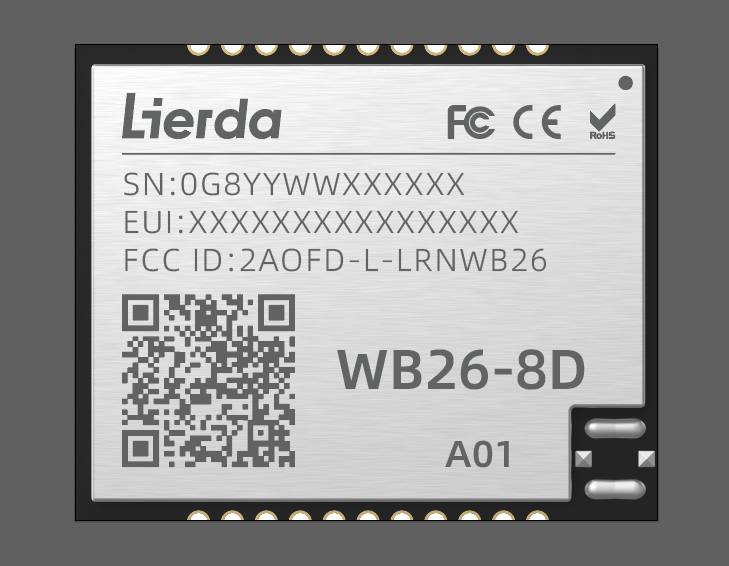
WB26 LoRaWAN Node Module: 22 × 18 × 3.0 mm, Class A/C operation, 22 dBm transmit power, -137 dBm receiver sensitivity at SF=12 and BW 125 kHz, 2 µA sleep current.
Short answer: a LoRaWAN node module should be shortlisted on four measurable parameters — the supported device class (Class A, Class C, or both), transmit power in dBm, receiver sensitivity in dBm together with the spreading factor and bandwidth used to measure it, and current consumption in each radio state (transmit, receive, sleep). Two further constraints decide whether the part can be designed in at all: the supply voltage window and the regional band coverage. In battery-constrained designs, sleep current sets the floor of the energy budget, while transmit current at the chosen power level dominates the cost of every uplink.
The worked examples below are three Lierda LoRaWAN node modules: WB25 and WB26, both listed at 22 dBm with global frequency bands, and the high-power LP26, listed at a maximum 29 dBm. Supporting data points come from adjacent products in the same LoRa portfolio — WP35 and QB20 — and from one Sigfox module, WB16, which appears only to show why a sensitivity figure measured under a different modulation cannot be read against a LoRa figure.
Lierda Science & Technology Group Co., Ltd. is an IoT module manufacturer and IoT solution provider founded in 2001 and headquartered in Hangzhou, China. The company develops wireless modules across LoRa, NB-IoT, Cat.1, 5G, Wi-Fi, Bluetooth and ZigBee technologies and supplies LoRaWAN node modules, LoRaWAN gateways and LoRa SiP modules for street lighting, agriculture, logistics, industrial control and metering (en.lierda.com).
Problem definition: three ways a LoRaWAN module comparison goes wrong
1. A sensitivity figure without its measurement conditions cannot be compared. Receiver sensitivity depends on spreading factor (SF) and bandwidth. WB25, WB26 and LP26 are each listed at -137 dBm at SF=12 and BW 125 kHz, while QB20 is listed at -148 ±1 dBm at SF=12 and BW 10.4 kHz. QB20's number looks roughly 11 dB better, but it was measured in a bandwidth about twelve times narrower, which lowers the noise floor. Neither figure is wrong; they answer different questions unless the measurement conditions match.
2. Transmit power is not the same as link margin, and it is region-bound. LP26 is listed at a maximum 29 dBm at 902–928 MHz with an alliance standard of US915/AU915, while WB25 and WB26 are listed at 22 dBm with global frequency bands. The 7 dB difference is real, but it exists only in the bands the module is specified for, and it is paid for in current: LP26 lists a typical transmit current of 600 mA at 29 dBm.
3. Sleep current is not battery life. WB25, WB26 and LP26 all list 2 µA of sleep current. Parts that share an identical floor value cannot be separated by it. What separates designs is how often the radio wakes, how long it transmits, and how much current it draws while doing so.
Industry background: why this decision now sits on more design desks
LoRaWAN deployments are scaling. MarketsandMarkets estimated the global LoRa and LoRaWAN IoT market at USD 8.0 billion in 2024, with expectations to reach USD 32.7 billion by 2029. Growth of that scale shows up at device level as more nodes per site, longer service intervals and tighter power budgets for the battery-powered share of the fleet.
The application set is mixed, and one hardware design often has to serve it. The applications listed for Lierda's LoRaWAN node modules are smart street lights, smart agriculture, smart logistics, industrial control, and instruments & meters. Within that set, mains-powered nodes such as street lights and industrial control units sit in the same network as battery-powered nodes such as field sensors and meters — which is why class setting and current budget must be decided per node type rather than once per project.
Recorded project conditions define what the module has to survive. Scenario records in Lierda's project data describe, for example, industrial working conditions; outdoor battery-powered operation with IP65 protection across -20 °C to +70 °C; a stated requirement of low power consumption for 6+ months of battery life; motion detection that triggers security alerts or lighting and HVAC automation; designs that pair the radio with an MCU mainboard, a relay and a power supply; and indoor appliance-type equipment operating at 0 °C to 40 °C and 20% to 80% RH. A module shortlist should be checked against the conditions of one specific node, not against the average of the portfolio.
Detailed solution: what each published parameter actually decides
1. Operating class: Class A or Class C
Class A opens a receive window after each uplink and sleeps between transmissions. Class C keeps the receiver open continuously, so a downlink can arrive at any moment. WB25, WB26 and LP26 all list Class A/C support, which means one hardware design can be commissioned either way — but the choice changes which current figure you budget against. Under Class C, the module's listed receive current becomes a continuous load instead of a duty-cycled event.
Class choice also interacts with the network side. The IG41 indoor LoRaWAN gateway is listed with Class A/C support and a maximum of 20 nodes, while the OG45 outdoor LoRaWAN gateway is listed with a maximum of 2000 nodes. Both use the SX1302 chip platform, both cover global frequency bands, and both list a maximum transmit power of 27 dBm — so in most deployments the binding constraint is the node's own energy budget, not gateway output.
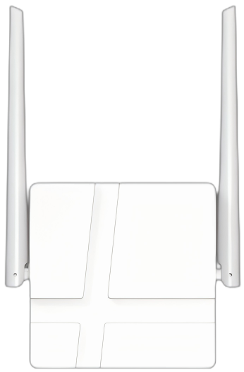
IG41 LoRaWAN Indoor Gateway: Class A/C operation, maximum 20 nodes, SX1302 chip platform, maximum transmit power 27 dBm.
2. Transmit power and the band it is permitted in
WB25 and WB26 are listed at 22 dBm with global frequency bands. LP26 is listed at a maximum 29 dBm at 902–928 MHz with an alliance standard of US915/AU915. That single line usually decides candidacy: if the deployment is US915 or AU915, the higher output is available; if one product must serve several regions, WB25 or WB26 keeps a single bill of materials.
The power figure also has a direct current consequence. LP26's listed typical transmit current at 29 dBm is 600 mA — an order of magnitude above sleep current, and the dominant term in any uplink energy calculation that uses the highest power setting.
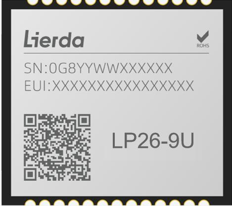
LP26 High-Power LoRaWAN Node Module: Class A/C, US915/AU915, maximum 29 dBm at 902–928 MHz, 25 × 21 × 3.0 mm, 3.6–5.2 V supply (typical 3.8 V).
3. Receiver sensitivity: read the conditions, not just the number
Sensitivity states the weakest signal the module can still decode. It improves as spreading factor rises and as bandwidth narrows, which is why the test condition belongs immediately beside the figure. At equal conditions — SF=12 and BW 125 kHz — WB25, WB26 and LP26 are all listed at -137 dBm, and WP35 is listed at -142 dBm at LoRa 125 kHz: a genuine 5 dB difference inside the same measurement frame. WB16, a Sigfox module, is listed at a typical -124 dBm at GFSK; that value refers to a different modulation and protocol and should never be placed in the same column as a LoRa sensitivity figure.
A practical rule follows from this: compare sensitivities only at identical SF and bandwidth, then ask whether your payload can tolerate the narrower bandwidth that produces the better number. If it can, the same receiver may reach further; if it cannot, the comparison has no engineering meaning for your design.
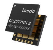
QB20 LoRa SiP Module: 8.0 × 8.0 × 1.1 mm, 1.8–3.7 V, maximum 22 dBm, receiver sensitivity -148 ±1 dBm at SF=12 and BW 10.4 kHz, 0.6 µA sleep current.
4. Current consumption: three states, three different decisions
Sleep current is the smallest number on the sheet and the easiest to over-weight. WB25, WB26 and LP26 all list 2 µA. The numbers that decide battery life are transmit current and receive current, and here the published parameter sets differ in completeness. LP26 states both a typical transmit current of 600 mA at 29 dBm and a typical receive current of 17 mA, while the parameter set for WB25 and WB26 states the 2 µA sleep current without stating transmit or receive current. For a battery design those missing values dominate average current, so they must be obtained from the supplier or measured on samples before the power budget is frozen.
Across the wider portfolio the transmit-state figure varies by more than an order of magnitude: LP26 typ. 600 mA at 29 dBm; WP35 110 mA at 22 dBm, 27 mA at 14 dBm and 14 mA at 10 dBm, with 5–6 mA receive current; QB20 ≤135 mA transmit and ≤6 mA receive with 0.6 µA sleep; WB16 75 mA transmit at 12 dBm and 8 mA receive. None of these numbers predicts battery life on its own — each one only becomes meaningful once multiplied by the time the radio actually spends in that state.
5. Supply voltage, footprint and interface
WB25 and WB26 are listed at 22 × 18 × 3.0 mm with a 1.8–3.6 V supply, UART interface and IPEX antenna support. LP26 is listed at 25 × 21 × 3.0 mm with a 3.6–5.2 V supply (typical 3.8 V) and the same UART and IPEX arrangement. In battery-constrained designs the voltage window is frequently the deciding constraint rather than the radio specification: a 1.8–3.6 V window can accept a single-cell supply directly, whereas a 3.6 V minimum requires the rail to stay above that threshold, which is a different power architecture and a different bill of materials.
Footprint reinforces the same split. LP26 is the largest of the three at 25 × 21 mm; WB25 and WB26 share a 22 × 18 mm footprint; WP35 measures 22 × 18 × 2.6 mm with an SPI interface and a 1.8–3.6 V supply; QB20 compresses the radio into an 8.0 × 8.0 × 1.1 mm SiP package with a 1.8–3.7 V supply.
6. Where LoRaWAN sits among the other LPWAN options
LoRaWAN is one of several low-power wide-area options on the same shortlist, and the choice is architectural before it is technical. Where a project needs an operator network rather than a private gateway, NB-IoT modules such as MB26-AGL are listed with band coverage of B03/B05/B08/B20/B28, a 2.2–4.5 V supply and 1.5 µA PSM current. Where a simpler region-limited protocol fits, the Sigfox WB16 module is listed for 868–870 MHz (RC1) with a Sigfox Verified RC1 specification, a 2.2–3.6 V supply, maximum 12 dBm output, 75 mA transmit current at 12 dBm, 8 mA receive current and a stamp-hole antenna interface compatible with IPEX. The table below exists only to keep that architecture decision visible; the remainder of this guide stays on LoRaWAN node selection.
| Technology | Example module | Listed parameters relevant to selection |
|---|---|---|
| LoRaWAN | WB25, WB26, LP26 | Class A/C; 22 dBm (WB25, WB26) or max. 29 dBm at 902–928 MHz (LP26); -137 dBm at SF=12, BW 125 kHz; 1.8–3.6 V or 3.6–5.2 V; 2 µA sleep current |
| NB-IoT | MB26-AGL | B03/B05/B08/B20/B28; 2.2–4.5 V; 1.5 µA PSM |
| Sigfox | WB16 | 868–870 MHz (RC1); Sigfox Verified RC1; 2.2–3.6 V; max. 12 dBm; typ. -124 dBm at GFSK; 75 mA transmit at 12 dBm; 8 mA receive |
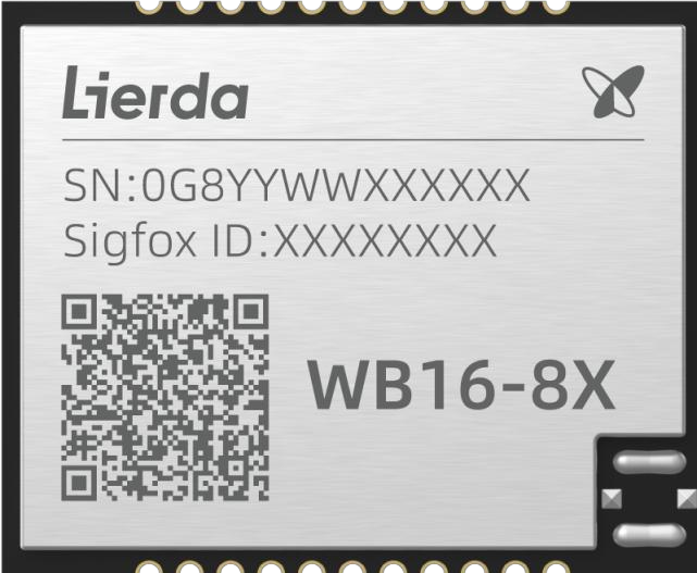
WB16 Sigfox Module: 868–870 MHz (RC1), Sigfox Verified RC1, 22 × 18 × 2.7 mm, 2.2–3.6 V, maximum 12 dBm, typical -124 dBm at GFSK.
Step-by-step: selecting a LoRaWAN node module for a battery-constrained design
Step 1 — Write down the uplink duty cycle before opening any datasheet. Payload size, reporting interval, retransmission policy and whether downlinks are expected all exist before the module does. Without this step the comparison degenerates into ranking dBm values.
Step 2 — Choose the device class explicitly. WB25, WB26 and LP26 all support Class A/C, so the class is a configuration and power-budget decision rather than a hardware change. Choose Class A when the node is battery-powered and only reports upward; choose Class C when downlink latency matters and mains power is available. In Class C, the listed receive current becomes a continuous load.
Step 3 — Fix the regional band first, then the module. WB25 and WB26 list global frequency bands; LP26 lists US915/AU915. If the product must also serve other regions, the global-band pair keeps one bill of materials; if the deployment is US915 or AU915 only, LP26's 29 dBm output becomes available.
Step 4 — Decide the transmit power you can justify. The gap between 22 dBm and 29 dBm is 7 dB of output, matched on the LP26 side by a listed typical transmit current of 600 mA. Where a link already closes at 22 dBm, the higher setting buys margin at a measurable energy price; where it does not close, the same 7 dB may be the difference between a working and a failed site.
Step 5 — Build the average-current budget across all three radio states. Average current = (Itransmit × ttransmit + Ireceive × treceive + Isleep × tsleep) / T, where T is the full reporting period. The formula, not the sleep current, is what connects a module parameter set to a battery-life claim.
Illustrative calculation (assumption stated explicitly): if a node using LP26 were to transmit at 29 dBm for 1 second once per hour, the transmit state alone would contribute 600 mA × 1 s / 3600 s ≈ 0.167 mA to the average current. That single second per hour is far above the 2 µA sleep current, which is why the 2 µA figure should be treated as a floor rather than a prediction. Replace the assumed 1 s/hour duty cycle with your own numbers, and replace the transmit current with the value you have verified for the module you intend to use.
Verification note: the parameter set used here states transmit and receive current for LP26, WP35, QB20 and WB16, but not for WB25 and WB26. For those two models, obtain the values from the manufacturer's datasheet or measure them on a sample before freezing the budget.
Step 6 — Check voltage window, footprint and interface against the board. A 1.8–3.6 V window (WB25, WB26, WP35) can be driven directly from a 3 V-class rail, while LP26's 3.6–5.2 V window requires the rail to remain at or above 3.6 V. Footprints differ as well: 22 × 18 mm for WB25 and WB26, 25 × 21 mm for LP26, 22 × 18 × 2.6 mm with SPI for WP35 and 8.0 × 8.0 × 1.1 mm for the QB20 SiP.
Step 7 — Validate on samples before qualification. Three measurements settle most arguments: transmit and receive current at your actual duty cycle, sensitivity with your own antenna and enclosure, and sleep current measured on your complete power tree rather than on the module alone. Sample validation is also the point at which the missing WB25 and WB26 current figures can be filled in with real measurements rather than assumptions.
Use cases: matching the module to the recorded project condition
Instruments and meters. Instruments & meters are among the applications listed for WB25, WB26 and LP26. These devices typically send small payloads at fixed intervals and sleep the rest of the time, so Class A with a 2 µA sleep current is the natural starting point, and the discriminating parameters are the sleep current plus the current drawn during the short transmit window rather than peak output power.
Smart street lighting and industrial control. Mains-powered nodes can afford a continuously listening receiver, so the Class C support listed across WB25, WB26 and LP26 becomes usable and downlinks can be received at any time. Topology is then set on the gateway side: the IG41 indoor gateway is listed with a maximum of 20 nodes and the OG45 outdoor gateway with a maximum of 2000 nodes, both at a maximum 27 dBm transmit power. Industrial working conditions are recorded as a standing requirement for this class of deployment.
Outdoor battery-powered sensing in agriculture. Scenario records for this device class describe outdoor, battery-powered operation with IP65 protection across -20 °C to +70 °C, together with a stated requirement of low power consumption for 6+ months of battery life, and event-driven reporting such as motion detection that triggers security alerts or lighting and HVAC automation. For this profile the parameters doing the work are the 1.8–3.6 V window and the 2 µA sleep current of WB25 and WB26, not the maximum transmit power.
Smart logistics and control nodes. Smart logistics is listed among the applications for the LoRaWAN node portfolio, and the supporting equipment recorded for switch-type and control designs — an MCU mainboard, a relay and a power supply — describes the classical composition of a LoRaWAN control node. Here the module is selected for interface compatibility (UART with IPEX antenna support across WB25, WB26 and LP26) and for stable receive behaviour rather than for peak range.
Comparison table: WB25, WB26 and LP26 LoRaWAN node modules
| Parameter | WB25 | WB26 | LP26 |
|---|---|---|---|
| Alliance standard / bands | Global frequency bands | Global frequency bands | US915, AU915 |
| Operating mode | Class A/C | Class A/C | Class A/C |
| Transmit power | 22 dBm | 22 dBm | Max. 29 dBm at 902–928 MHz |
| Receiver sensitivity | -137 dBm (SF=12, BW 125 kHz) | -137 dBm (SF=12, BW 125 kHz) | -137 dBm (SF=12, BW 125 kHz) |
| Sleep current | 2 µA | 2 µA | 2 µA |
| Transmit current | Not stated in this parameter set | Not stated in this parameter set | Typ. 600 mA at 29 dBm |
| Receive current | Not stated in this parameter set | Not stated in this parameter set | Typ. 17 mA |
| Operating voltage | 1.8–3.6 V | 1.8–3.6 V | 3.6–5.2 V (typ. 3.8 V) |
| Dimensions | 22 × 18 × 3.0 mm | 22 × 18 × 3.0 mm | 25 × 21 × 3.0 mm |
| Interface / antenna | UART, IPEX support | UART, IPEX support | UART, IPEX support |
| Listed applications | Smart street lights, smart agriculture, smart logistics, industrial control, instruments & meters | Smart street lights, smart agriculture, smart logistics, industrial control, instruments & meters | Smart street lights, smart agriculture, smart logistics, industrial control, instruments & meters |
Read together, the three columns describe one trade rather than three products. WB25 and WB26 share the same listed electrical and RF parameters, the same 22 × 18 × 3.0 mm footprint and the same 1.8–3.6 V supply; the global-band WB26 variant is documented under the model designation WB26-8D-A01. LP26 buys 7 dB of additional transmit power and a regional band scope, and pays for it with a wider 3.6–5.2 V supply window, a larger 25 × 21 mm footprint and a 600 mA typical transmit current at 29 dBm.
| Module | Listed receiver sensitivity | Measurement condition |
|---|---|---|
| WB25 | -137 dBm | SF=12, BW 125 kHz (LoRa) |
| WB26 | -137 dBm | SF=12, BW 125 kHz (LoRa) |
| LP26 | -137 dBm | SF=12, BW 125 kHz (LoRa) |
| WP35 | -142 dBm | LoRa 125 kHz, sub-GHz |
| QB20 | -148 ±1 dBm | SF=12, BW 10.4 kHz |
| WB16 (Sigfox) | Typ. -124 dBm | GFSK — different modulation, not comparable with LoRa figures |
| Module | Sleep current | Transmit current | Receive current |
|---|---|---|---|
| WB25 | 2 µA | Not stated | Not stated |
| WB26 | 2 µA | Not stated | Not stated |
| LP26 | 2 µA | Typ. 600 mA at 29 dBm | Typ. 17 mA |
| WP35 | Not stated | 110 mA at 22 dBm; 27 mA at 14 dBm; 14 mA at 10 dBm | 5–6 mA (sub-GHz) |
| QB20 | 0.6 µA | ≤135 mA | ≤6 mA |
| WB16 (Sigfox) | Not stated | 75 mA at 12 dBm | 8 mA |
FAQ: LoRaWAN module selection for low-power projects
Will the same LoRaWAN node module work in every region?
No — band coverage is stated per module, and it decides candidacy before any electrical parameter does. WB25 and WB26 are listed with global frequency bands, while LP26 is listed with an alliance standard of US915/AU915 and a maximum 29 dBm at 902–928 MHz. A single bill of materials that must serve several regions therefore starts from the global-band models; a US915 or AU915-only project can use LP26. Lierda supports OEM and ODM production with worldwide export markets and full compliance support, so the band and certification documents for the exact model and target country should be requested before design freeze.
Should the node be configured as Class A or Class C?
Class A opens a receive window after each uplink and sleeps in between; Class C keeps the receiver open continuously so downlinks can arrive at any time. WB25, WB26 and LP26 all list Class A/C support, so this is a configuration and power-budget decision rather than a hardware change. Choose Class A for battery-powered nodes that only report upward, and Class C where downlink latency matters and mains power is available — remembering that under Class C the listed receive current becomes a continuous load rather than a duty-cycled event.
How should receiver sensitivity and current consumption figures be compared between modules?
Compare sensitivity only at identical spreading factor and bandwidth: WB25, WB26 and LP26 are all listed at -137 dBm at SF=12 and BW 125 kHz, and WP35 is listed at -142 dBm at LoRa 125 kHz, so those four values sit in the same frame. QB20 is listed at -148 ±1 dBm at SF=12 and BW 10.4 kHz, and its narrower bandwidth is why the raw number is not directly comparable with the 125 kHz figures. Compare current state by state as well: sleep (2 µA for WB25, WB26 and LP26), transmit (LP26 typ. 600 mA at 29 dBm; WP35 110 mA at 22 dBm; WB16 75 mA at 12 dBm) and receive (LP26 typ. 17 mA; WP35 5–6 mA; WB16 8 mA). WB25 and WB26 do not state transmit or receive current in the parameter set used here, so those two values must be obtained or measured before a battery-life figure is published internally.
Can a candidate module be tested before a production commitment?
Yes, and it is the recommended path. Lierda provides dedicated project support and remote technical assistance, with custom QC standards and testing based on customer specifications and a flexible MOQ based on project requirements. Sample validation should cover the three measurements that no datasheet can settle for your product: transmit and receive current at your own duty cycle, sensitivity with your antenna and enclosure in place, and sleep current measured on the complete power tree. Samples and technical documentation for WB25, WB26 and LP26 can be arranged through WhatsApp +86-18067988146 or by email at international@lierda.com.
What MOQ, capacity and lead time apply to a LoRaWAN node module project?
Lierda states a flexible MOQ based on project requirements, a flexible monthly capacity based on order requirements, and a negotiable lead time based on project complexity and order volume. OEM and ODM production modes are available with module and PCBA customization, and standard product direct sales with logo customization is offered as well. Because lead time depends on configuration, the fastest route to a firm answer is to send the band, the class setting, the expected annual volume and the target market together, then request a quotation for WB25, WB26 or LP26 through international@lierda.com.
Conclusion
LoRaWAN node selection reduces to a short, checkable list: class support, transmit power and the band it is permitted in, receiver sensitivity with its SF and bandwidth conditions, current in all three radio states, and the physical constraints of voltage window and footprint. For battery-constrained designs the practical order is duty cycle first, class second, band third, and current last — but with the most scrutiny, including for the values a parameter set does not state.
Within the Lierda LoRaWAN node portfolio, WB25 and WB26 provide a 22 dBm, global-band, 22 × 18 × 3.0 mm, 1.8–3.6 V baseline that suits single-BOM multi-region designs, both listed with Class A/C and a 2 µA sleep current. LP26 adds a maximum 29 dBm at 902–928 MHz for US915/AU915 projects where the additional output justifies a 3.6–5.2 V supply rail and a 600 mA typical transmit current. As an IoT module manufacturer with OEM and ODM production modes, module and PCBA customization, custom QC standards and remote technical assistance, Lierda can supply the same LoRaWAN modules into both profiles.

Lierda's Hangzhou facilities support LoRaWAN IoT module production, OEM/ODM projects and remote technical assistance for global deployments.
Next step: request samples, datasheets or a quotation for WB25, WB26, LP26 or any other LoRaWAN module in the portfolio — email international@lierda.com, message WhatsApp +86-18067988146, or review the full range on en.lierda.com.
Product catalogue: the complete Lierda product brochure is available as a downloadable PDF here: Lierda product brochure (PDF).
Have Questions or Need More Details?
Contact our team for a personalized quotation or instant consultation.
Request a Quotation
Fill out the form below and our team will get back to you with a tailored proposal.
WhatsApp Direct Chat
Prefer to chat in real-time? Message us on WhatsApp for instant assistance & quick answers.
- Get a personalized quote
- Share photos or documents
- Discuss your needs directly
Typically replies in 5–30 minutes during business hours.