
Pressure Control Switch Application Guide: Mechanical, Float & Pump Control by Scenario
Matching a pressure control switch to a real project is a three-question exercise rather than a catalogue exercise. First: what does the device actually sense — line pressure or tank level? Second: what pressure band must the system hold, and what head can the pump deliver at start-up? Third: where will the device live — a dry pump house, a submerged sump, an outdoor irrigation cabinet, or a temporary site connection? Answer those three and the component family narrows itself: a mechanical pressure control, a float switch, or an integrated pump pressure controller.
This guide works through four application scenarios — domestic water supply, agriculture irrigation, water treatment and construction — and shows how Monro Switch assigns different hardware to each duty. Monro Switch (Zhejiang Monro Machinery & Electronic Co., Ltd.) is a Wenling City, Zhejiang-based manufacturer of pump controllers, pressure switches and float switches. The company was formally established in 2010 and draws on more than 20 years of pressure-control and float-switch manufacturing experience, with a current range of more than 40 pressure controller models for water pump systems and air compressors.
Why one pressure control switch cannot cover four scenarios
A domestic booster holds a narrow pressure band at low flow. An irrigation line runs long duty cycles at high flow, often drawing from a reservoir. A water treatment tank is level-driven, not pressure-driven. A construction connection is temporary, exposed, frequently re-wired, and fed from whatever supply the site has that week. The same device cannot be right for all four, and the reason is structural: each scenario asks the control to sense a different variable, hold a different band, and survive a different environment.
In practice, four mis-matches account for most application problems:
- Wrong sensed variable. A pressure device installed on a tank-fill duty cannot see level; a float switch on a pressurized line cannot see pressure.
- Wrong pressure band or wrong unit. Most mechanical KRS controls are published in PSI ranges while integrated EPC controllers are published in bar, so a specification written in one unit and ordered in the other drifts before installation even begins.
- Wrong enclosure rating. An IP20 mechanical control and an IP65 integrated controller can solve the same switching problem, but not in the same location.
- Wrong head margin. A starting pressure the pump cannot support produces a controller that runs and never cuts out, or cuts out and never restarts.
None of these is a product defect. Each is a selection decision, and each can be closed before the order is placed.
Industry background: two control families sharing one pump
Electromechanical pressure switches accounted for approximately 62% of the global pressure switch market in 2024, with solid-state electronic pressure switches at 38%, according to Market Research Future (report published 25 February 2026). That split matters at specification stage, because both families will normally be quoted on the same project — and they are not interchangeable at installation level.
The governing standard is equally explicit about device type. IEC 60730-2-6:2025, published by the International Electrotechnical Commission on 14 August 2025, applies to automatic electrical pressure sensing controls for use in, on, or in association with equipment for household appliance and similar use. A specification that names the standard gives the supplier something to certify against; a specification that names only a function does not.
Read together, the two facts give the working rule for this guide: mechanical controls remain the default where a simple, field-adjustable on/off function is enough, and integrated electronic controllers are chosen where run-dry protection, constant pressure or simplified wiring belong in the requirement. Both appear in the scenarios below, and neither is universally better.
The three component families and what each one actually controls
Mechanical pressure control (KRS series)
A mechanical pressure control starts and stops the water pump automatically according to the set pressure. The KRS series covers that duty with field-adjustable cut-in and cut-out points, and the published specifications show where the variants sit:
- KRS-6: rated 110–240 V, 50/60 Hz, 16(8) A, low-pressure protection 10–3 PSI, steel flange, 1/4"F, 3/8"F and 1/4"M screw types, IP44, 55 °C maximum working temperature.
- KRS-3: rated 110–240 V, 12 A, minimum cut-in 20 PSI, maximum cut-out 100 PSI, pressure ranges of 20–40, 30–50, 40–60, 50–70 and 60–90 PSI, steel or plastic flange, IP20, 55 °C.
- KRS-4: pressure ranges of 20–40, 30–50, 40–60 and 50–70 PSI, minimum cut-in 20 PSI, maximum cut-out 100 PSI.
- KRS-8: pressure range 1–6 bar or 6–12 bar, minimum cut-in 1 bar, maximum cut-out 12 bar, 110–240 V/400 V, 20(16) A, IP44, 55 °C, 1/4" or 3/8" female connection.
Two details are easy to miss. The KRS-6 carries low-pressure protection at 10–3 PSI, which is what cuts a pump when suction is lost. And the family is documented in two unit systems — PSI for most models, bar for the KRS-8 — so unit discipline starts at the data sheet, not at the installation.
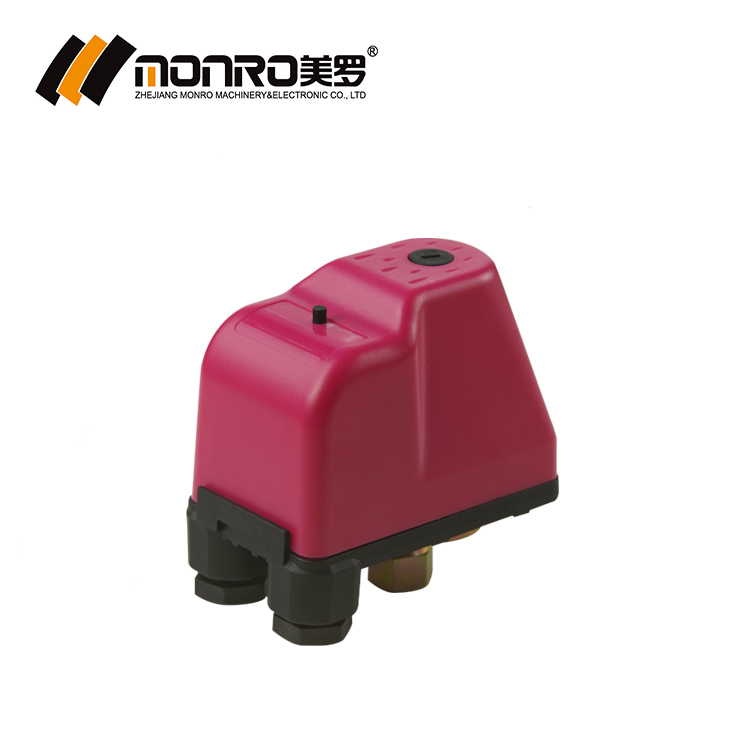
KRS-6 mechanical pressure control — IP44, 55 °C, low-pressure protection 10–3 PSI.
Float switch (FPS series)
A float switch senses liquid level and switches a pump or valve on that basis. The FPS-3 and FPS-4 are rated 250 V, 50/60 Hz, 16(8) A, IP68 and 55 °C maximum working temperature, and both are wired for three duty modes: auto-fill, auto-drainage with lack-water protection, and a combined fill-and-drain auto-switch mode. Cable is offered at 2 m, 3 m and 5 m in PVC or rubber, with 3 × 1.0 mm² recommended. Because the sensed variable is level, a float switch complements a pressure control rather than replacing it.
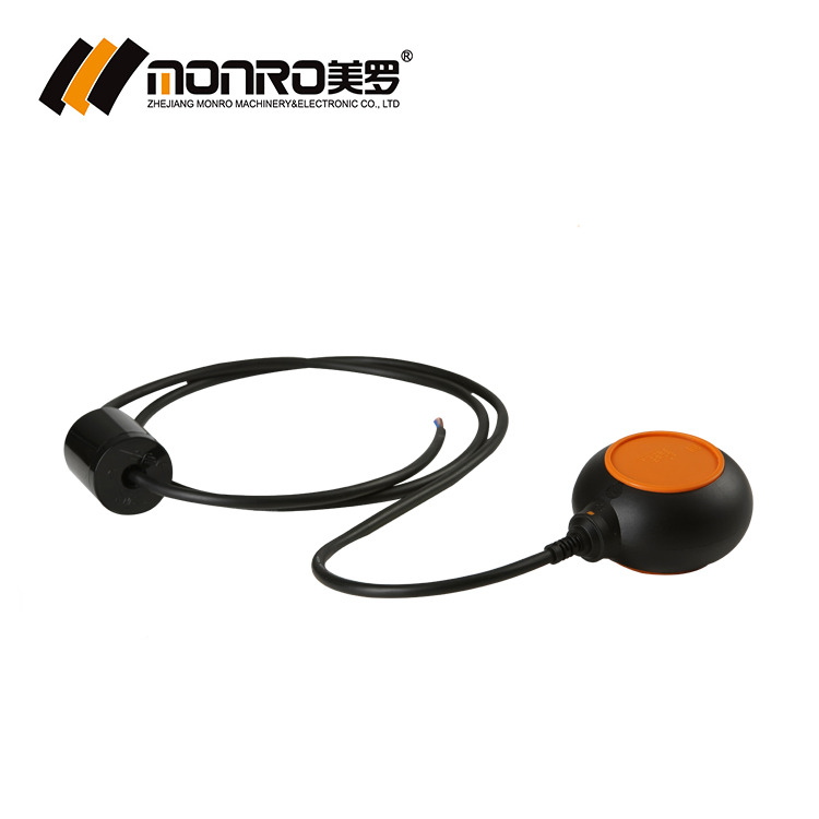
FPS-3 float switch — IP68, 250 V, 16(8) A, auto-fill and auto-drainage modes.
Pump pressure controller (EPC series)
An integrated pump pressure controller combines pressure sensing, switching and — on most models — a built-in check valve and built-in run-dry protection in one housing. The EPC-3 maintains constant pressure at constant flow, includes a pressure gauge for real-time pressure monitoring, a built-in check valve and built-in run-dry protection, is rated G1", IP65 and 55 °C, and is set at 1.2, 1.5 or 2.2 bar starting pressure. The EPC-3P adds an adjustable starting pressure range of 1.2–2.5 bar and switches off automatically when there is water shortage.
Adjacent models cover adjacent duties. The EPC-5.1 offers G1" or NPT1" connection at IP44 with a 1.2–2.5 bar adjustable range. The EPC-16 is rated IP65 and 60 °C, with toolless starting-pressure adjustment from 1.0 to 3.0 bar and a 10 bar maximum working pressure. The EPC-19 regulates outlet pressure from 2.0 to 6.0 bar with a 2–6 bar starting-pressure setting, and adds rotor anti-blocking protection that runs the pump for 10 seconds after 24 hours stopped. The EPC-10 works differently again: a two-in-one unit with a manual mode for non-tower supply and a time mode for filling a water tower, starting pressure 0.5–9.3 bar, stopping pressure 0.7–9.5 bar, and timing settings of 0.1–1 H and 1–24 H.
Scenario 1 — Domestic and residential water supply
Domestic supply is the most tightly defined of the four duties. The recorded working condition for this application is clean water at 220–240 V / 110–120 V, a pressure range of 0.5–10 bar, 55 °C maximum working temperature and IP65 protection, with the controller starting and stopping the pump in response to system pressure: activating at the preset low-pressure setpoint and deactivating at the high-pressure setpoint. The EPC-1.1 is the model matched to this duty.
Three EPC-1.1 characteristics do most of the work in a residential installation. Triple voltage coverage — 110 V, 230 V or 110–240 V — lets one part number serve 110 V and 230 V markets, which cuts the number of variants a distributor has to hold and removes a common source of wrong-voltage installation. Built-in run-dry protection covers the case where the suction side runs empty, whether from a municipal interruption or an empty break tank. The built-in check valve prevents backflow and helps stop the short cycling that follows a pressure drop at the pump outlet.
Starting pressure is set against the height the water must reach, not against habit. A 1.2 bar start suits single-level distribution and short pipe runs; 1.5 bar suits outlets on a second level; 2.2 bar suits long risers and outlets well above the pump. The 2025 catalogue lists the full model matrix if you need to compare configurations side by side.
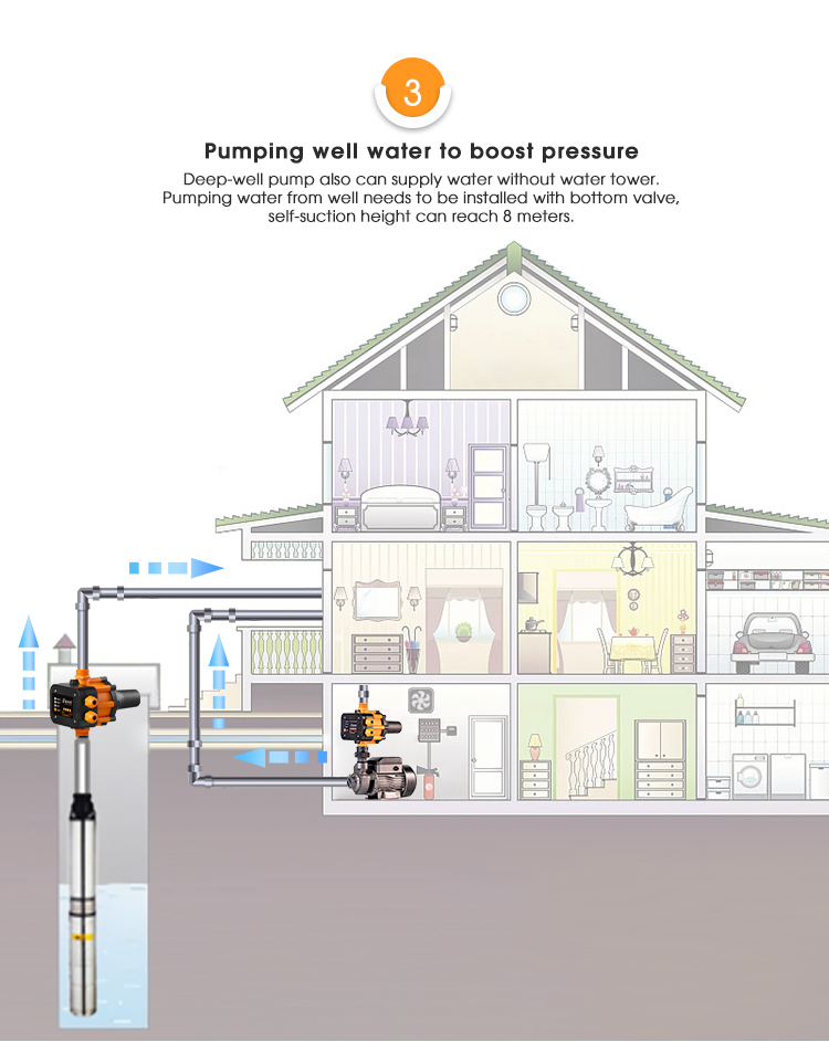
Integrated EPC controller on a domestic supply line — G1" connection, IP65 housing.
Scenario 2 — Agriculture irrigation
Irrigation inverts the domestic priorities. Duty cycles are long, flow rates are higher, suction usually comes from a reservoir, canal or storage tank, and the controller often sits in an outdoor cabinet that sees dust, sun and seasonal shutdowns. The control has to protect the pump at least as much as it has to hold pressure.
The EPC-2 is the model listed for this duty: built in plastic and metal, and matched in the recorded application data to agriculture irrigation and construction. Its starting pressure settings are 1.2 bar, 1.5 bar or 2.2 bar, so the same height rule applies — the highest emitter or sprinkler head above the pump sets the floor for starting pressure. A recorded 50-piece retail order covering agriculture irrigation, water treatment and construction duty has run for two years with reliable automatic pressure control for a water supply system, which is the typical shape of an irrigation order: modest quantity, long service, repeat purchase.
Two accessories make the irrigation installation more robust. The KRS-6 mechanical control carries low-pressure protection at 10–3 PSI, which stops the pump when suction is lost — a routine event on a canal intake as water levels fall. And an FPS float switch at the source tank, wired in the lack-water protection mode, stops the pump before the intake runs dry.
Boundary condition: the recorded working condition for these controls specifies clean water as the working medium. Slurries, abrasive solids and heavily loaded water sit outside that scope and should not be assumed to be handled by the same model without a specific engineering review.
Scenario 3 — Water treatment and tank management
Water treatment is the scenario where pressure control is usually the wrong first question. Tank filling, sump emptying, backwash cycling and transfer between tanks are level-driven duties, and the float switch is the primary device. The FPS-3 and FPS-4 are IP68 rated and therefore suitable for submersion, switch 16(8) A at 250 V, and are wired in three distinct modes: auto-fill for supply tanks, auto-drainage with lack-water protection for sumps and pump protection, and a combined fill-and-drain mode for cycling between two levels.
Where a treatment plant needs timed rather than level-based filling, the EPC-10 covers it. Its time mode is intended for filling a water tower, with timing settings selectable between 0.1–1 H and 1–24 H, and its manual mode serves non-tower supply. Pressure control re-enters the picture on the distribution side, where a controller holds pressure on the outlet line after treatment.
Two specification checks apply here. Temperature ceilings differ inside the range — 55 °C for the FPS float switches and the EPC-1.1, 60 °C for the EPC-10, EPC-12, EPC-16 and EPC-19 — so a plant with elevated water temperature must be specified from the higher-rated models. And these are control devices: they start, stop and protect pumps, and they do not treat, test or monitor water quality.
EPC-3P adjustable starting pressure range of 1.2–2.5 bar, with automatic switch-off during water shortage.
Scenario 4 — Construction site water supply
Construction combines the worst of the other three. Supply quality is unpredictable, voltage varies between temporary connections, equipment is relocated, wiring is redone by whoever is on site, and the pump is often the cheapest unit available. The selection rule that survives this environment is the least clever one: choose the widest-tolerance device that still protects the pump.
The EPC-2 is listed for construction as well as irrigation, and its plastic-and-metal construction suits the handling a site imposes. Where a simple on/off function is all that is needed, a mechanical KRS control is the economical choice — but the enclosure rating decides placement. The KRS-3 is IP20 and belongs inside a protected enclosure; the KRS-6 and KRS-8 are IP44 and tolerate a more exposed position. Wide-range voltage coverage of 110–240 V on the KRS models and triple voltage on the EPC models reduces the risk of a controller being connected to the wrong site supply.
Wiring discipline matters more on site than in any other scenario. The commissioning guidance is explicit: connect the controller's power cord to a separate plug wire and seal all wire joints with waterproof insulating tape. A joint that is mechanically sound but not sealed is the most common avoidable failure in temporary installations.
Step-by-step: from pump nameplate to a running controller
This sequence applies to every automatic pump controller in the range, regardless of scenario, and it is worth running in order because each step can invalidate the next.
- Verify the pump on its own. Check that the water pump operates normally before the controller is connected, and that the parameters on the pump nameplate match those of the pressure controller.
- Confirm the head margin. The pump head must be at least 0.8 bar higher than the controller's start-up pressure. This single check prevents the majority of run-and-never-cut-out complaints.
- Match motor power. Select the controller variant whose maximum power covers the pump motor — the EPC-3 and EPC-3P list 0.55 kW, 1.1 kW, 1.5 kW and 0.75 kW variants, the EPC-16 lists 1.5 kW and 0.75 kW, and the EPC-19 reaches 2.2 kW.
- Set the starting pressure from usable height. Starting pressure × 10 m gives the maximum water-use height, and (starting pressure + 0.8 bar) × 10 m gives the minimum pump lift.
- Install in the direction of flow. Fit the controller in accordance with the arrow marked on its housing.
- Wire and seal. Connect the power cord to a separate plug wire and seal every joint with waterproof insulating tape.
- Commission with valves open. Open the main outlet valve and all water faucets first, then connect the power supply; the controller will then begin operating.
Starting pressure: 1.2, 1.5 and 2.2 bar as decision points
Starting pressure is the setting buyers most often copy from a previous project, and the one that most directly determines whether the installation works. The published rule is simple: starting pressure × 10 m equals the maximum water-use height, and the pump must deliver at least (starting pressure + 0.8 bar) × 10 m of head.
| Starting pressure | Maximum water-use height | Minimum pump lift required | Typical fit |
|---|---|---|---|
| 1.2 bar | 12 m | 20 m | Single-level distribution, short runs, low-rise supply |
| 1.5 bar | 15 m | 23 m | Outlets on a second level, medium risers |
| 2.2 bar | 22 m | 30 m | Long risers, outlets well above the pump |
The 1.2 bar row is the worked example given in Monro's selection guidance. The 1.5 bar and 2.2 bar rows apply the same rule to the other two standard settings and are calculated values, not measured results — they show the arithmetic the specification has to satisfy, and the pump curve still has to deliver the lift at the flow the system actually draws.
Where a fixed setting is too coarse, the adjustable models give a continuous range instead: 1.2–2.5 bar on the EPC-3P and EPC-5.1, 1.0–3.0 bar toolless adjustment on the EPC-16, and a 2–6 bar starting-pressure setting on the EPC-19, which also auto-sets start pressure from the regulated outlet pressure.
Connection threads: G1", NPT1" and the smaller mechanical connections
Thread choice is a purchasing decision disguised as a technical one, because the wrong thread stops a project at the commissioning stage. The integrated EPC models are published with G1" connections on the EPC-3, EPC-3P, EPC-12, EPC-16 and EPC-19, and with either G1" or NPT1" on the EPC-5.1. The EPC-10 uses smaller hydraulic connections — 1/4" and 3/8" female, or 1/4" and 1/2" male. The mechanical KRS controls use 1/4"F, 3/8"F, 1/4"M and 3/8"M screw types, with KRS-6 and KRS-3 offering 1/4"F, 3/8"F and 1/4"M, and KRS-8 offering 1/4" or 3/8" female.
Two rules keep this simple. First, specify the thread standard with the market, not with the warehouse: G and NPT threads differ in form and sealing method, and a G1" model is not an NPT1" model with a different label. Second, where project pipework calls for G1 1/4" or G1 1/2", confirm the thread on the selected controller before ordering rather than planning to adapt a G1" body with a reducer on site.
Scenario-to-component comparison
The table below compares the three families on the dimensions that decide a project specification. Values are taken from the published model data for the listed representative models and do not apply automatically to other models in the same family.
| Decision dimension | Mechanical pressure control (KRS) | Float switch (FPS) | Pump pressure controller (EPC) |
|---|---|---|---|
| Sensed variable | Line pressure | Liquid level | Line pressure, integrated control |
| Representative model | KRS-6 / KRS-3 | FPS-3 / FPS-4 | EPC-1.1 / EPC-2 / EPC-3 |
| Setting basis | Cut-in and cut-out in PSI (KRS-8 in bar) | Switch position by float level | Starting pressure 1.2 / 1.5 / 2.2 bar |
| Electrical rating | 110–240 V, 16(8) A (KRS-6) | 250 V, 16(8) A | 0.55–2.2 kW depending on model |
| Protection rating | IP44 (KRS-6), IP20 (KRS-3) | IP68 | IP65 (EPC-1.1, EPC-3, EPC-16) |
| Max working temperature | 55 °C | 55 °C | 55 °C (EPC-1.1, EPC-3), 60 °C (EPC-16, EPC-19) |
| Connection | 1/4"F, 3/8"F, 1/4"M | Cable 2 m / 3 m / 5 m | G1" or NPT1" depending on model |
| Best-fit scenario | Irrigation and construction, simple on/off duty | Treatment tanks, sumps, source protection | Domestic supply, automatic boosting, pump protection |
| Main limitation to plan for | Cut-in and cut-out must be set in the field; ranges published in PSI | Senses level only; not a pressure device | Start pressure must sit at least 0.8 bar below available pump head |
Mis-matches to catch before the order is placed
Most field failures attributed to these controls trace back to one of eight checks that were never made in the specification. They take minutes to close and are cheaper than a return:
- Working medium. The recorded working condition specifies clean water; do not assume a standard model covers solids-loaded or abrasive water.
- Temperature ceiling. Confirm whether the duty needs the 55 °C models or the 60 °C models.
- Enclosure rating against location. IP20 indoors in an enclosure, IP44 for exposed positions, IP65 for outdoor integrated control, IP68 for submersion.
- Unit system. State PSI or bar explicitly and convert before ordering, not after delivery.
- Head margin. Verify pump head is at least 0.8 bar above the chosen start-up pressure.
- Motor power. Match the controller's maximum power to the pump motor, not to the previous project.
- Thread standard and size. Confirm G or NPT and the exact size against the pipework drawing.
- Float switch cable. Fix length (2 m, 3 m, 5 m) and material (PVC or rubber) at order stage, with 3 × 1.0 mm² recommended.
Frequently asked questions
Which certifications and standards should a pressure control switch carry for water systems?
Monro Switch operates an ISO 9001:2015 quality management system and holds TUV (Germany) and CE (Europe) certification for its pressure controls, with selected models also approved under the CUL standard for the United States and Canada. On the standards side, IEC 60730-2-6:2025 is the current international standard covering automatic electrical pressure sensing controls for household and similar use, so a specification should name the standard the certificate is issued against rather than only the certificate mark. The destination market decides which approvals apply, and the certificate should be requested against the exact model and voltage variant being ordered.
How do I choose an automatic pump controller for a specific pump and lift?
Two checks decide it. Match the controller's maximum motor power to the pump motor: the EPC-3 and EPC-3P list 0.55 kW, 1.1 kW, 1.5 kW and 0.75 kW variants, the EPC-16 lists 1.5 kW and 0.75 kW, and the EPC-19 reaches 2.2 kW. Then set starting pressure from the height the water must reach — with a 1.2 bar start, the maximum water-use height is 1.2 × 10 m = 12 m, and the pump must deliver at least (1.2 + 0.8) × 10 m = 20 m of head. The 0.8 bar margin is the minimum by which pump head must exceed the controller's start-up pressure.
Can one float switch handle both tank filling and drainage?
The FPS-3 and FPS-4 are wired for three duties: auto-fill, with the blue line connected to the electric pump; auto-drainage and lack-water protection, with the brown line connected to the pump; and a combined fill-and-drain auto-switch mode. Both models are rated 250 V, 50/60 Hz, 16(8) A, IP68 and 55 °C maximum working temperature. Because they sense level rather than pressure, they cannot replace a pressure controller on a pressurized line, but they can protect the pump at the source end of the same system.
What drives the cost of a pressure control switch order?
Four factors move the number. The model family sets the baseline, because a mechanical KRS control and an integrated EPC controller are different assemblies. The customization scope comes next: cable length, cable material, brand, color box and color are all listed as customizable, and each adds a setup. Order quantity is measured against the recorded 204-piece MOQ. The voltage and thread variant completes the picture. Every unit is 100% tested, which is part of production cost rather than an optional add-on. Specify model, voltage, thread, starting pressure and cable requirement in the enquiry so that competing quotations compare like with like.
Can I validate a sample before committing to production?
Sampling should be planned before the order rather than after it. Define the exact configuration to be tested — model, rated voltage, connection thread, starting pressure setting and cable requirement — and test it on the pump it will actually control, because the 0.8 bar head margin and the maximum water-use height are properties of the system, not of the controller. Color, color box, branding, cable length and cable material are listed as customizable, so all five should be frozen at sample stage; changing them later reopens tooling and setup work.
What lead time and production capacity should a project plan for?
The recorded OEM arrangement lists a 45-day lead time and a 204-piece MOQ against monthly capacity of 180,000 EPC automatic pump controllers, 250,000 KRS pressure switches and 30,000 FPS float switches and liquid level controls. Because capacity is large relative to the minimum order, the binding constraint on most projects is the customization and testing cycle rather than raw output. Plan the 45 days before shipping and site commissioning, and confirm the current figure in writing at order stage, since it is a production-planning number rather than a delivery guarantee. To start, send the scenario, pump details and thread requirement through the Monro Switch contact channel and request a configuration-matched quotation or the 2025 catalogue.
Conclusion: choose the scenario, then the setting
The four scenarios in this guide resolve to four different control decisions. Domestic supply takes an integrated controller such as the EPC-1.1, where triple voltage, run-dry protection and a built-in check valve remove the most common residential failure modes. Agriculture irrigation takes the EPC-2 plus a low-pressure mechanical control and a source-side float switch, because protecting the pump from suction loss matters as much as holding pressure. Water treatment takes the float switch as the primary device, with pressure control reserved for the distribution side. Construction takes the widest-tolerance device on the shortest decision path, wrapped in enclosure and wiring discipline.
In every case the order is the same: identify the sensed variable, calculate the height the system must serve, confirm the pump head exceeds the chosen start-up pressure by at least 0.8 bar, then fix the thread, voltage and enclosure rating against the actual installation. Setting and thread mistakes are cheap to prevent at specification stage and expensive to discover at commissioning.
Match the controller to the scenario
Share the application, pump motor rating, required height and pipework thread, and the Monro Switch team will confirm the model, starting pressure and connection details against the project — or send a sample request with your configuration frozen.
Download the Monro catalogue 2025 (PDF) or visit monroswitch.com for the full model matrix.
Have Questions or Need More Details?
Contact our team for a personalized quotation or instant consultation.
Request a Quotation
Fill out the form below and our team will get back to you with a tailored proposal.
WhatsApp Direct Chat
Prefer to chat in real-time? Message us on WhatsApp for instant assistance & quick answers.
- Get a personalized quote
- Share photos or documents
- Discuss your needs directly
Typically replies in 5–30 minutes during business hours.