
Core Parameters for SMT Line Integration: Sizing Pick, Place, and Reflow Systems
An SMT turnkey solution performs to the level of its weakest interface, not to the level of its best datasheet. Three shared parameters set that level: the board handling envelope that every conveyor module must agree on, the cycle time balance between stations, and the repeatability of the reflow thermal profile. This guide works through the engineering parameters that must align when a pick and place machine, a reflow oven, and an automatic online glue dispenser are specified as one line — with the arithmetic and the checkpoints a buyer can apply before the purchase order is signed.
A machine datasheet answers a machine-level question: how fast, how accurate, how wide. A turnkey line answers a different question — which parameters do the machines share, and what shared value do they agree on? Answer that question first and the rest of the configuration follows. Skip it and every product changeover becomes a manual intervention on the floor, regardless of how impressive the individual machines looked in the quotation.
Why Individually Capable Machines Still Underperform as a Line
Machine-level specifications are almost always written for one machine running at its optimum condition. A placement system rated at 92,000 CPH, a reflow oven with eight top and eight bottom heating zones, and an automatic online glue dispenser handling a 50–450 mm board range can each be technically correct on paper and still form an inefficient line if the parameters they share were never aligned before purchase. The interface, not the machine, is where throughput is won or lost.
In practice, the recurring failure modes are predictable:
- Width mismatch. The board set is sized against the widest module envelope rather than the narrowest, so boards that convey cleanly through the mounter cannot pass through a downstream station without a mechanical change.
- Transfer height mismatch. Modules are levelled independently instead of to a single conveyor datum, producing edge lifting, sensor mis-triggers, and jams at the transfer point.
- Direction mismatch. Conveyor flow direction is assumed rather than confirmed, which turns a straightforward line into a re-engineering project after installation.
- Takt mismatch. Rated optimum speed is used as the planning figure, so the calculated line rate never survives contact with a real product mix, and one station silently becomes the bottleneck.
- Thermal drift. The reflow profile is developed once and then allowed to shift when exhaust capacity, board loading, or conveyor speed changes.
- Changeover mismatch. Program storage and teaching method are treated as software details, when in fact they determine how long a high-mix line is stopped between products.
None of these are exotic engineering problems. They are sizing errors, and they are cheapest to fix on paper, before the machines are on the floor.
The Market Context Behind Line Sizing Decisions
The commercial weight of these decisions keeps increasing. Transparency Market Research valued the global surface mount technology (SMT) equipment market at approximately USD 6.6 billion in 2025 and projects it to reach USD 14.6 billion by 2036. That is a market where equipment is bought in multi-machine configurations rather than as individual units, which makes interface engineering a first-order procurement skill rather than a technical afterthought.
The same research attributes a 54% revenue share of the 2025 SMT equipment market to Asia-Pacific, ahead of North America and Europe. Regional concentration matters for line sizing because equipment availability, spare-part logistics, and engineering support proximity all influence how much integration risk a buyer can absorb.
Within the equipment market, placement equipment — pick and place machines — is the largest single segment, accounting for approximately 38% to 48% of total SMT equipment market value according to Persistence Market Research and Cognitive Market Research. The reflow and dispensing stages are smaller in value terms but carry disproportionate risk, because errors there are thermal or material errors that surface later as solder defects rather than as immediate throughput losses.
The mix of work is also shifting. Mordor Intelligence projects the High-Mix/Low-Volume assembly line segment to grow at a CAGR of 8.31% through 2031, driven by demand for customized industrial and medical electronics. Meanwhile, Persistence Market Research identifies 3D AOI (Automated Optical Inspection) and SPI (Solder Paste Inspection) as the fastest-growing equipment sub-sectors at a reported 15.2% CAGR, driven largely by automotive zero-defect requirements. The practical consequence for line sizing is that tolerance headroom, not raw speed, is increasingly the parameter buyers regret skimping on.
Acceptance criteria are equally well defined. IPC-A-610J, released in March 2024 by IPC International, is the current global standard for the acceptability of electronic assemblies and defines Class 1, Class 2, and Class 3 quality levels. A line configuration should be sized against the class its end products must meet, because solder joint acceptance criteria differ between classes.
The vendor landscape is led by a small group of global players — ASMPT Limited, Fuji Corporation, Yamaha Motor, Panasonic, Juki Corporation, and Hanwha Precision Machinery are listed among the key global SMT vendors by MarketsandMarkets. Fuji Corporation's NXT platform and Yamaha's YSM series (for example the YSM20R) are established as industry-standard modular mounters for high-speed and high-precision placement. Buyers therefore usually build a turnkey configuration from a mix of platform generations and price tiers, which is precisely why the interface parameters matter more than brand consistency.
The Four Parameter Layers That Must Align
Sizing a turnkey line can be reduced to four layers of alignment. Each layer has at least one hard number and at least one decision rule attached to it.
Layer 1 — Board Handling Envelope: Width, Length, Transfer Height, and Direction
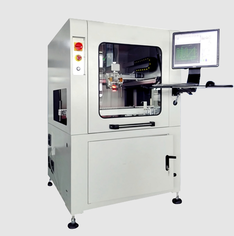
Board handling is the first thing to align because it is the only parameter every machine in the line physically shares. The Hanwha Decan S2 SMT pick and place machine handles PCB sizes from 50 × 40 mm to 510 × 460 mm in its standard configuration. The HMH830D automatic online glue dispenser handles a PCB width range of 50–450 mm, transfers boards at a height of 920 ± 20 mm, runs in either L→R or R→L direction, and moves boards at a transport speed of 0–5,000 mm/min using two stepper motors.
Read together, those figures contain the single most useful integration fact available to a buyer: the glue dispenser's 450 mm maximum width is narrower than the mounter's 510 mm maximum width. The line's usable board width is therefore set by the narrowest module in the chain, not by the widest.
Applied to this configuration, that reads as 450 mm minus the clearance needed for edge handling. Any product intended to run above 450 mm in width needs either a different dispensing arrangement or a documented decision to route it around the dispenser. Making that decision during specification is free; making it after installation is not.
Transfer height works the same way. A dispenser transfer height of 920 ± 20 mm is a datum, not a preference. Every conveyor module, loader, unloader, buffer, and inspection station should be levelled to that datum so that the tolerance band is consumed by normal mechanical variation rather than by accumulated installation error. Direction should be locked in writing: L→R flow with a single defined reference edge prevents the classic first-week surprise where one module was built for R→L.
Layer 2 — Cycle Time Balance: From Rated CPH to Real Takt
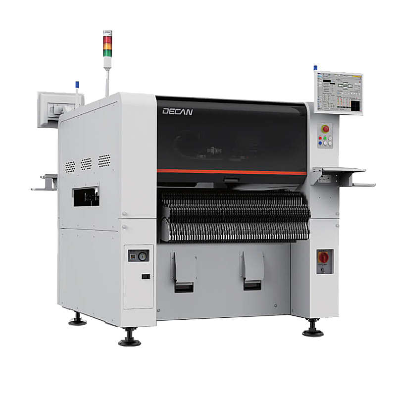
Cycle time alignment starts with an honest reading of the placement specification. The Hanwha Decan S2 is rated at 92,000 CPH optimum with the HS10 head, using a structure of 2 gantry × 10 spindles per head. The word that carries the risk is “optimum”. Optimum conditions assume ideal component distribution, no feeder replenishment interruptions, and no board transfer overhead. A real product mix almost never reproduces those conditions, so the planning figure should be a measured effective rate for the actual program, not the catalogue optimum.
Sizing then becomes arithmetic. First establish the target takt from demand:
Then convert placement capability into time per board:
Run the same calculation for the paste printing, dispensing, inspection, and reflow stages. The largest resulting number is the line's takt, and it will not be the placement stage unless the product is unusually dense or the machine is unusually slow. On a high-mix line, glue dispensing and inspection frequently become the pacing stations because their cycle time depends on program length and inspection coverage rather than on a fixed mechanical rate. The dispenser's transport speed of 0–5,000 mm/min is a range, not a cycle time — the actual dispensing time is defined by the program created through manual teaching.
The decision rule is straightforward: balance the line to the second-largest station, not to the largest, so that normal variation in the slowest station does not immediately become a bottleneck. Then verify the balance with a real program before purchase, not with a theoretical component count.
Layer 3 — Thermal Repeatability in the Reflow Stage
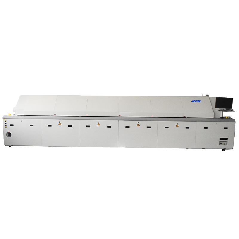
Reflow is where parameter alignment becomes thermal rather than mechanical, and where repeatability matters more than peak capability. The XMR-800D SMT reflow oven provides top 8 / bottom 8 heating zones across a 3,110 mm heating tunnel, top 3 / bottom 3 cooling zones, and a small circulation rectifying plate structure. It requires an exhaust volume of 11 m³/min × 2. Its dimensions are 5,520 × 1,430 × 1,530 mm and it weighs approximately 2,710 kg.
Two of those numbers drive facility decisions that are easy to defer and expensive to retrofit. The 2,710 kg mass is a floor-loading and vibration question, particularly on mezzanine or upper-floor installations. The 11 m³/min × 2 exhaust requirement is a ducting and plant-capacity question — if exhaust falls short of the specified rate, flux volatiles are not removed consistently and the thermal profile drifts between the profile that was developed and the profile the line actually runs.
Dwell time in the heating tunnel is set by conveyor speed and can be calculated directly:
That formula is the reason thermal repeatability is an integration parameter rather than an oven parameter. If the mounter's effective rate changes — because a new product has more components, or because a feeder format slows placement — the operator's instinct is to change conveyor speed to maintain output. Every change of conveyor speed rewrites the thermal profile. The correct sequence is to fix the profile window first, confirm the exhaust and loading conditions that make it repeatable, and then treat conveyor speed as a controlled variable rather than an output adjustment.
Layer 4 — Dispenser Programming, Placement Accuracy, and Component Range
The fourth layer is where turnaround time is decided. The HMH830D automatic online glue dispenser is controlled by an industrial computer with a motion control card, operated from a computer interface, and programmed by manual teaching. It stores more than 1,000 running programs. Its rack size is L1,060 × W1,200 × H1,700 mm and it weighs 650 kg.
Program storage is not a minor feature on a high-mix line. With more than 1,000 programs retained, a taught dispensing pattern can be recalled rather than recreated when a product returns to the schedule. On a mix driven by customized industrial and medical electronics — the segment Mordor Intelligence projects to grow at 8.31% CAGR through 2031 — changeover time, not dispensing speed, is usually the constraint on daily output.
Placement accuracy belongs in the same layer because accuracy and dispensing interact. The Hanwha Decan S2 achieves ±28 μm Cpk ≥ 1.0 on 03015 chip components and ±25 μm Cpk ≥ 1.0 on ICs, and handles parts from 03015 up to 12 mm with a maximum height of 10 mm. A Cpk value of 1.0 or better indicates that the placement distribution fits within the tolerance band with margin — the relevant test when fine-pitch ICs and 03015 chips share a board with a dispensed adhesive pattern, where placement offset and dispense offset compound rather than cancel.
A Seven-Step Sizing Sequence for a Turnkey SMT Configuration
The four layers convert into a sequence that can be run as a specification checklist before any machine is ordered.
- Fix the board envelope. Collect the full product board set and record maximum and minimum length and width. Set the line's usable width as the minimum across all modules — 450 mm in the configuration discussed here — and confirm the minimum board size each module accepts, including the 50 × 40 mm lower limit of the mounter.
- Fix the transfer datum and direction. Adopt 920 ± 20 mm as the conveyor datum and require every module to be levelled to it. Lock the flow direction (L→R or R→L) in the purchase specification, and confirm it on the loader, printer, dispenser, mounter, oven, and unloader.
- Set the takt target. Calculate required boards per shift and derive target takt in seconds per board. This single number governs every subsequent sizing decision.
- Compute time per board at each station. Use measured effective rates rather than optimum ratings, and use components per board divided by effective CPH for the placement stage.
- Size the oven against the profile, not against the takt. Confirm that the 3,110 mm heating tunnel and the top 8 / bottom 8 zone arrangement can hold the required profile at the conveyor speed the takt demands, and verify exhaust capacity at 11 m³/min × 2, floor loading for approximately 2,710 kg, and footprint of 5,520 × 1,430 × 1,530 mm.
- Configure dispensing programs and storage. Plan the program library before installation so that more than 1,000 stored programs are structured by product family rather than accumulated ad hoc.
- Lock the environment and ESD conditions. Confirm the room can hold the specified operating conditions and that the ESD protection measures are in place before commissioning, not after.
Where These Parameters Bite Hardest: Application Scenarios
The alignment rules above apply to every SMT line, but the consequences differ by product family. The scenarios below are typical of the environments in which these configurations run: automotive electronics, smart transportation, industrial automation, consumer electronics, medical technology, new energy systems, LED and optoelectronics, and telecommunications.
Automotive electronics and smart transportation. Zero-defect requirements push inspection coverage up, which is consistent with the reported 15.2% CAGR for 3D AOI and SPI. That coverage adds stations to the line, and every added station is another conveyor height and another takt to balance. In this scenario, Layer 1 and Layer 2 are effectively one decision.
Medical device PCB assembly. Cleanroom operation under ISO Class 8 conditions with humidity held at 40–60% RH makes the environment a controlled parameter rather than a background condition. Fine-pitch ICs and small chip components make the Cpk ≥ 1.0 accuracy figures relevant, because a placement margin that is acceptable in a general-purpose line can be insufficient when combined with a dispensed adhesive pattern.
Industrial control PCB production and power supply module SMT. These boards typically carry higher thermal mass. Board mass is the reason the 3,110 mm heating tunnel and the eight-zone top and bottom configuration matter more here than in consumer work: the profile has to deliver the required soak and reflow energy across a heavier assembly without raising conveyor speed beyond what the dwell calculation allows.
5G communication equipment and telecom boards. High layer counts and dense placement make the effective placement rate the dominant variable, and make substrate size variation a board handling risk rather than a theoretical one.
Consumer electronics SMT lines. Here the takt calculation is the whole conversation. Volume is high, margins are thin, and the cost of a two-second imbalance at one station compounds across every shift.
LED display SMT assembly and new energy systems. Panel sizes in these product families often sit close to the upper width limits of the handling envelope, which is exactly where the difference between a 450 mm dispenser range and a 510 mm mounter range becomes a routing decision rather than a specification detail.
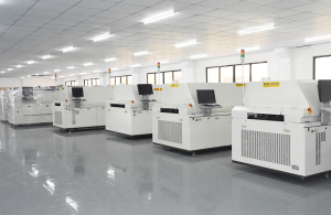
In practice these configurations are specified as a full line rather than as isolated machines: loader, solder paste printer, SPI, pick and place machine, automatic online glue dispenser, reflow oven, unloader, AOI, X-ray inspection, ICT, splice machine, PCB turner, NG separator, stencil cleaner, environment monitor, and ESD protection. The operating environment assumed for such a line is an indoor cleanroom at 23°C ± 2°C and 50% ± 10% RH with IP20/IP40 protection, zero vibration, zero dust, ESD-protected zones, and continuous 24/7 operation.
Integration Parameters at a Glance
The table below sets out the parameters that carry integration weight for each of the three systems discussed. Values are the published specifications of the models referenced in this guide; where a parameter is not defined for a given system, it is not a comparison point.
| Integration parameter | SMT Pick And Place Machine — Hanwha Decan S2 | SMT Reflow Oven — XMR-800D | Automatic Online Glue Dispenser — HMH830D |
|---|---|---|---|
| Primary integration constraint | Placement rate and accuracy versus the required board mix | Thermal window, exhaust capacity, and floor loading | Board width range and transfer height compliance |
| Board / process width | 50 × 40 mm to 510 × 460 mm (standard) | Not specified for this model | PCB width range 50–450 mm |
| Transfer height | Not specified for this model | Not specified for this model | 920 ± 20 mm |
| Throughput / transport | 92,000 CPH optimum (HS10 head) | Conveyor speed sets dwell: 3,110 mm ÷ speed | Transport speed 0–5,000 mm/min |
| Process zones / structure | 2 gantry × 10 spindles per head | Top 8 / bottom 8 heating; top 3 / bottom 3 cooling; small circulation rectifying plate | Industrial computer plus motion control card; manual teaching |
| Precision / repeatability | ±28 μm Cpk ≥ 1.0 (03015 chip); ±25 μm Cpk ≥ 1.0 (IC) | Heating zone length 3,110 mm | Program-dependent; more than 1,000 stored programs |
| Component / material range | 03015 to 12 mm, height 10 mm | Thick copper plate construction | PCB width 50–450 mm |
| Footprint (L × W × H) | Not specified for this model | 5,520 × 1,430 × 1,530 mm | 1,060 × 1,200 × 1,700 mm |
| Weight | Not specified for this model | Approximately 2,710 kg | 650 kg |
| Facility requirement | Single conveyor datum and direction | Exhaust 11 m³/min × 2 | Two stepper motors; L→R (R→L) transfer direction |
Frequently Asked Questions
Which standard defines whether a PCBA leaving an SMT turnkey line is acceptable?
IPC-A-610J, released by IPC International in March 2024, is the current global standard for the acceptability of electronic assemblies. It defines three quality levels — Class 1, Class 2, and Class 3 — and the acceptance criteria for solder joints differ between them. A line configuration should therefore be sized and inspected against the class the end product requires, not against a single generic acceptance level.
How do I confirm that the pick and place machine, reflow oven, and glue dispenser share a compatible board and transport envelope?
Compare the handling specifications directly. The Hanwha Decan S2 SMT pick and place machine accepts boards from 50 × 40 mm up to 510 × 460 mm in its standard configuration. The HMH830D automatic online glue dispenser accepts PCB widths of 50–450 mm and transfers boards at a height of 920 ± 20 mm, in either L→R or R→L direction. The usable width of the line is set by the narrowest module in the chain, so any board above 450 mm wide requires a deliberate decision about how it is routed. Level every module to the same 920 mm datum within the ±20 mm tolerance, and confirm that conveyor direction is identical from loader to unloader.
Where should budget be concentrated when sizing an SMT turnkey configuration?
Placement equipment is the largest single segment of SMT equipment spending, accounting for approximately 38% to 48% of total SMT equipment market value according to Persistence Market Research and Cognitive Market Research — a reflection of the fact that placement rate and accuracy usually set the line's takt. Two other cost centres are commonly underestimated. The reflow stage carries facility cost as well as machine cost: the XMR-800D weighs approximately 2,710 kg and requires an exhaust volume of 11 m³/min × 2. Inspection is the fastest-growing sub-sector, with 3D AOI and SPI reported at a 15.2% CAGR driven by automotive zero-defect requirements, so coverage decisions should be made at specification stage rather than added later at a premium.
Can a configuration be validated before the full line is committed?
Validation is primarily a parameter exercise, not a hardware exercise. Take the customer board set, identify the widest and narrowest panels, and test them against every module envelope — including the 450 mm width limit of the dispenser and the 50 × 40 mm lower limit of the mounter. Calculate target takt from required boards per shift, then calculate time per board for each station using effective rather than optimum rates. Confirm the thermal dwell using tunnel length divided by conveyor speed, and confirm that the program library will hold the expected number of dispenser programs — the HMH830D stores more than 1,000. Board dimensions, component mix, and volume targets are the three inputs a supplier needs in order to confirm a configuration, and Motek's contact channels for that review are listed at the end of this article.
What applies after an SMT turnkey line is installed?
Motek provides a 12-month warranty on its products, with support handled through the same contact channels used for the initial enquiry. For lifecycle planning, three assets are worth documenting during commissioning because they are the ones that must be reproduced after a changeover or a component substitution: the dispenser's taught programs, the oven's thermal profile settings, and the mounter's placement programs. The full equipment catalogue is available as a downloadable brochure, and sample or quotation requests can be sent to sales@morequip.com or by WhatsApp at +86 199 2455 0176.
Conclusion
An SMT turnkey solution is sized correctly when the machines agree on four things: how wide the board is, how high the conveyor sits, how long each station takes, and how stable the thermal profile is at the speed that takt demands. Each of those has a number attached to it — 450 mm of usable board width, 920 ± 20 mm of transfer height, a takt expressed in seconds per board, and a dwell time derived from a 3,110 mm heating tunnel. Confirming those four numbers before purchase is a paper exercise. Confirming them afterwards is a project.
Motek, a Shenzhen-based SMT equipment supplier founded in 2011, configures pick and place, reflow, dispensing, and cleaning equipment for lines serving the EU, USA, AU, CA, and ASEAN markets. The parameters discussed here are the same ones used to specify a configuration — board dimensions, component mix, target takt, and facility conditions.
Next step: size your line against real numbers
Download the full equipment brochure, or send your board dimensions and volume targets for a configuration review, sample, or quotation.
Download the SMT equipment brochure (PDF) | www.morequip.com | sales@morequip.com | WhatsApp: +86 199 2455 0176
Have Questions or Need More Details?
Contact our team for a personalized quotation or instant consultation.
Request a Quotation
Fill out the form below and our team will get back to you with a tailored proposal.
WhatsApp Direct Chat
Prefer to chat in real-time? Message us on WhatsApp for instant assistance & quick answers.
- Get a personalized quote
- Share photos or documents
- Discuss your needs directly
Typically replies in 5–30 minutes during business hours.