
How a Seamless Flow from Dispensing to Reflow Transforms Electronics Assembly
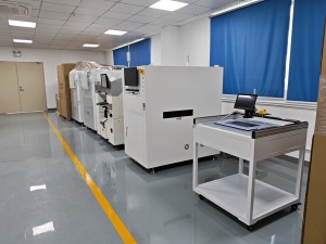
A seamless flow from dispensing to reflow means the PCB leaves the glue dispenser, enters the pick and place machine, and moves into the reflow oven as one continuous conveyor-linked sequence — no manual transfer, no re-orientation, no re-stacking. That single change removes the handling steps where most assembly errors and idle time are created.
Electronics assembly does not get faster because one machine speeds up. It gets faster when the board never has to stop being a board in process. This application guide explains how the three stages — automatic online glue dispensing, placement, and reflow — are linked into one flow, which parameters actually control the handoff, and how the same sequence is adapted between high-volume runs and mixed-product batches.
The reference configuration discussed here is built from Motek's automatic online glue dispenser (HMH830D), the Hanwha Decan S2 pick and place machine, and the XMR-800D SMT reflow oven. Motek is an SMT equipment supplier based in Shenzhen, Guangdong, founded in 2011, operating a 955 m² facility with 31 employees, and exporting 100% of its output to the EU, US, Australia, Canada, and ASEAN markets. This is the equipment set that defines a practical SMT turnkey solution for factories that run more than one product type.
Problem Definition: Why Three Good Machines Can Still Make a Slow Line
The most common throughput loss in SMT assembly is not a slow machine. It is a broken handoff between machines.
When dispensing, placement, and reflow are treated as three separate islands, the board has to travel between them in a non-productive way:
- Manual or semi-manual transfer that requires an operator to move, stack, or re-load boards between stations.
- Re-orientation, where a board dispensed in one direction is fed into the next machine from another.
- Buffers that grow into queues, so upstream stations idle while downstream stations starve.
- Product changeover that forces a partial reset of the sequence, because each station is programmed and adjusted independently.
- Handling errors — every time a board is physically touched, there is an opportunity to misalign it, drop it, or reverse it.
The framing that fixes this is simple: the line is one process, and each machine is a stage of that process. Board handling therefore belongs inside the process specification, not in the gaps between three separate purchase decisions. When handling is treated as an afterthought, it silently absorbs capacity that the machines were bought to provide.
Industry Background: Why Transfer Continuity Now Decides Competitiveness
Market data explains why the handoff has become a procurement criterion rather than a shop-floor detail.
- The global SMT equipment market was valued at approximately USD 6.6 billion in 2025 and is projected to reach USD 14.6 billion by 2036 (Transparency Market Research).
- Asia-Pacific held a 54% revenue share of the SMT equipment market in 2025, followed by North America and Europe (Transparency Market Research).
- Placement equipment is the largest single segment, accounting for roughly 38%–48% of total SMT equipment market value (Persistence Market Research / Cognitive Market Research).
- The high-mix / low-volume assembly segment is projected to grow at a CAGR of 8.31% through 2031, driven by demand for customized industrial and medical electronics (Mordor Intelligence).
- 3D AOI and SPI inspection are among the fastest-growing equipment sub-sectors, expanding at a 15.2% CAGR on the back of automotive zero-defect requirements (Persistence Market Research).
Two implications follow. First, most new capacity is being bought to run more product variants per shift, not simply more boards. Second, quality acceptance is tightening: IPC-A-610J, released in March 2024, remains the current global standard for the acceptability of electronic assemblies and defines Class 1, Class 2, and Class 3 quality levels (IPC International). More variants plus tighter acceptance means the cost of a broken handoff rises faster than the cost of a slow spindle.
On the equipment side, the reference platforms buyers compare are well established. Fuji Corporation's NXT platform and Yamaha's YSM series (for example, YSM20R) are industry-standard modular mounters for high-speed and high-precision placement (Fuji / Yamaha official product catalogs), and the key global SMT vendors include ASMPT Limited, Fuji Corporation, Yamaha Motor, Panasonic, Juki Corporation, and Hanwha Precision Machinery (MarketsandMarkets). What those platforms share is that they are bought as part of a sequence, not as standalone units — which is exactly the logic the dispensing-to-reflow flow formalises.
Detailed Solution: One Continuous Board Path — Dispenser, Placer, Reflow
The flow described here has three linked stations and one shared principle: the board is transferred by conveyor at every boundary, in one direction, without being handled. In a linked layout, the conveyor segments between stations are treated as part of the process design, so the board enters the dispensing stage, passes through placement, and enters the reflow tunnel in the same orientation throughout.
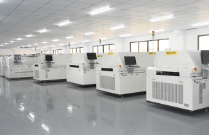
Station 1 — Automatic Online Glue Dispenser (HMH830D)
The dispensing stage is where the sequence begins. Its function is to place adhesive on the board inline, so the board is never removed from the conveyor to be processed.
- Rack size (L × W × H): 1060 mm × 1200 mm × 1700 mm; weight 650 kg.
- Equipment platform: T20 mm steel plate, chrome plated.
- Control method: industrial computer plus motion control card; operation by computer control.
- Programming mode: manual teaching; running program storage quantity: more than 1000 programs.
- PCB transfer height: 920 ± 20 mm.
- Transportation speed: 0–5000 mm/min; transfer direction L→R (R→L).
- Transmission motors: 2 stepper motors.
- PCB width range: 50–450 mm.
For a linked flow, the two numbers that matter most are the 920 ± 20 mm PCB transfer height and the bidirectional transfer direction. The first fixes the datum at which the board leaves the dispensing stage. The second means the machine can sit at either end of the sequence without changing the product's tooling concept — a detail that decides how easily an existing floor plan can be converted into a continuous path.
Station 2 — Pick and Place Machine (Hanwha Decan S2)
Placement is the throughput-defining stage. Its parameters set the takt that the dispensing and reflow stages have to live with.
- Speed: 92,000 CPH (optimum, HS10 head).
- Structure: 2 gantry × 10 spindles per head.
- Accuracy: ±28 μm, Cpk ≥ 1.0 (03015 chip); ±25 μm, Cpk ≥ 1.0 (IC).
- Component size range: 03015 to 12 mm, height 10 mm.
- PCB size: 50 × 40 mm to 510 × 460 mm (standard).
- Frame material: high-strength aluminum alloy.
The precision figures are the reason the flow has to be seamless rather than merely fast. A ±28 μm placement accuracy at 03015 chip scale is only meaningful if the board arrives at the placement stage in exactly the position and orientation in which it was dispensed. Any manual transfer or re-orientation between the two stations puts that accuracy at risk before a single component is placed.
Station 3 — SMT Reflow Oven (XMR-800D)
Reflow closes the sequence. It has to accept boards at production cadence and deliver a repeatable thermal profile across the full board width.
- Number of heating zones: top 8 / bottom 8; heating zone length 3110 mm.
- Number of cooling zones: top 3 / bottom 3.
- Rectifying plate structure: small circulation.
- Exhaust volume requirement: 11 m³/min × 2 (exhausts).
- Dimensions (L × W × H): 5520 mm × 1430 mm × 1530 mm; weight approximately 2710 kg.
- Body material: thick copper plate; color: computer grey.
The 8 + 8 heating structure with a 3110 mm heating length is what allows the oven to be treated as a stage of a continuous flow rather than a batch step: boards pass through in sequence, so the queue between placement and reflow remains a transfer rather than a stockpile.
The Three Interface Rules That Actually Make the Flow Seamless
- Transfer height continuity. The dispenser releases the board at a PCB transfer height of 920 ± 20 mm. In a linked line, the conveyor segments on either side of that boundary are aligned to that datum, so the board never has to be lifted or dropped between stages.
- Cadence matching instead of buffer stacking. The dispenser moves boards at 0–5000 mm/min, while the placer defines takt at up to 92,000 CPH (optimum, HS10 head). Matching these two rhythms — one moving boards, one placing components — is what keeps the conveyor a pacing element rather than a queue.
- Program continuity across the batch. With manual teaching and storage for more than 1000 running programs, the dispenser's changeover between products becomes a program recall rather than a mechanical reset. That is what allows the same physical flow to serve a high-volume run in the morning and a mixed-product run in the afternoon.
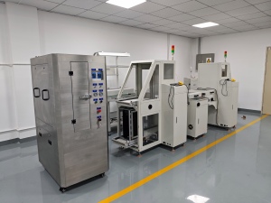
Step-by-Step Breakdown: A Production Run on a Linked Line
The following eight steps describe how a batch moves through the linked sequence in practice. Each step corresponds to a verifiable capability of the referenced equipment.
- Program the batch. The dispensing program is taught manually and stored. Repeat orders are recalled from the machine's library of more than 1000 running programs, so the flow starts from a known state rather than from a re-setup.
- Confirm the board path. PCB width is checked against the dispenser's 50–450 mm range and the placement stage's 50 × 40 mm to 510 × 460 mm standard PCB size. Boards outside the configured range are a setup decision, not a mid-run adjustment.
- Dispense inline. Adhesive is applied while the board remains on the conveyor, at a transfer height of 920 ± 20 mm and a transport speed of 0–5000 mm/min. The board is not removed, flipped, or re-stacked.
- Transfer without handling. The board passes directly to the next stage, following the machine's L→R (R→L) transfer direction. This is the step that removes the largest single source of handling error in an unlinked line.
- Place components. The placer runs at up to 92,000 CPH (optimum, HS10 head) across 2 gantries × 10 spindles per head, positioning components from 03015 to 12 mm at ±28 μm (03015 chip) and ±25 μm (IC) accuracy, both at Cpk ≥ 1.0.
- Feed the reflow tunnel. Boards enter the oven in the same orientation and sequence in which they were dispensed and populated. No re-orientation occurs between stages.
- Reflow and cool. The board travels through 8 top / 8 bottom heating zones over a 3110 mm heating length, then through 3 top / 3 bottom cooling zones, with a small-circulation rectifying plate structure stabilising the profile across the board. Exhaust is specified at 11 m³/min × 2.
- Hand off to verification and downstream stations. After reflow, the flow continues into inspection stations such as AOI or SPI, and then into depaneling and cleaning. Motek's product range covers this downstream territory with PCB cutting machines and cleaning machines, which is what makes a single-vendor SMT turnkey solution practical rather than theoretical.
Adapting the Same Flow to Different Batch Types
The value of a linked flow is that it does not have to be rebuilt when the batch type changes. Three parameters carry most of that adaptation.
- Program depth. More than 1000 stored running programs on the dispenser mean product variety is handled at the program level. A mixed-product day becomes a sequence of recalls rather than a sequence of mechanical re-setups.
- Board width envelope. The 50–450 mm dispenser range and the 50 × 40 mm to 510 × 460 mm placement range define the practical size envelope of the line. Products inside that envelope can share the same flow.
- Transfer direction. L→R (R→L) transfer gives layout flexibility: the dispensing stage can sit at either end of the sequence depending on the available floor space.
For high-volume runs, the constraint shifts to cadence: the placement stage at 92,000 CPH sets the pace, and the flow's job is to keep boards arriving without gaps. For mixed-product runs, the constraint shifts to changeover: the flow's job is to make each program switch short and repeatable, so setup time does not consume the capacity gained by automating the transfer. Motek supports this adaptation stage with production line layout design and remote or on-site training as part of the turnkey scope.
Use Cases: Where the Linked Flow Pays Back
A five-year production record illustrates what a linked dispensing-to-reflow flow delivers in real SMT factory conditions. Motek supplied 20–35 units to SMT factory clients in Germany, Israel, India, and Australia, used across smartphone motherboard assembly, tablet computer circuit board production, ECU control unit assembly, LED display modules, LED streetlight drivers, and consumer electronics smartphone PCB assembly running at 50,000 units per month. The reported outcome is mass production of 20,000–100,000 pieces per day, with the application characterised as high density, high efficiency, and high reliability.
Two scenarios show how that translates into day-to-day operation:
- High-volume, low-variety runs. A single board type runs for long periods. Transfer continuity removes accumulated handling time, and the reflow oven's 8 + 8 heating zone structure keeps throughput stable across the shift.
- Mixed-product, high-mix runs. Boards change frequently within a shift. Program recall on the dispenser and a shared board-width envelope let the physical line stay in place while only the programs change — the practical requirement behind the 8.31% CAGR that Mordor Intelligence reports for the high-mix / low-volume assembly segment through 2031.
In both scenarios the same design decision produces the benefit: the board is dispensed, populated, and reflowed without ever being manually handled in between. That is also where handling-error reduction comes from — not from a single anti-error device, but from the removal of the handling steps themselves.
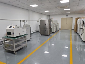
Comparison Table: How Each Station Contributes to Flow Continuity
| Flow stage | Referenced machine | Verified parameters | Contribution to a seamless flow |
|---|---|---|---|
| Dispensing | Automatic online glue dispenser HMH830D | Rack size 1060 × 1200 × 1700 mm; weight 650 kg; T20 mm chrome-plated steel platform; industrial computer + motion control card; manual teaching; more than 1000 stored running programs; PCB transfer height 920 ± 20 mm; transport speed 0–5000 mm/min; transfer direction L→R (R→L); 2 stepper motors; PCB width 50–450 mm | Starts the sequence inline, sets the transfer-height datum, and turns batch changeover into a program recall |
| Placement | Hanwha Decan S2 pick and place machine | 92,000 CPH (optimum, HS10 head); 2 gantry × 10 spindles per head; ±28 μm Cpk ≥ 1.0 (03015 chip); ±25 μm Cpk ≥ 1.0 (IC); components 03015–12 mm, height 10 mm; PCB 50 × 40 mm to 510 × 460 mm; high-strength aluminum alloy | Defines line takt and requires the board to arrive in exactly the dispensed position and orientation |
| Reflow | XMR-800D SMT reflow oven | Top 8 / bottom 8 heating zones; heating zone length 3110 mm; top 3 / bottom 3 cooling zones; small-circulation rectifying plate; exhaust 11 m³/min × 2; 5520 × 1430 × 1530 mm; approx. 2710 kg; thick copper plate | Accepts boards continuously at line cadence and stabilises the thermal profile across the full board |
How to read this table: the column that matters for procurement is the last one. Machine specifications tell you what each station can do in isolation; the contribution column tells you whether the three stations can be operated as one process.
Compliance and Line Acceptance
A linked flow still has to pass acceptance. Two documents underpin the equipment side:
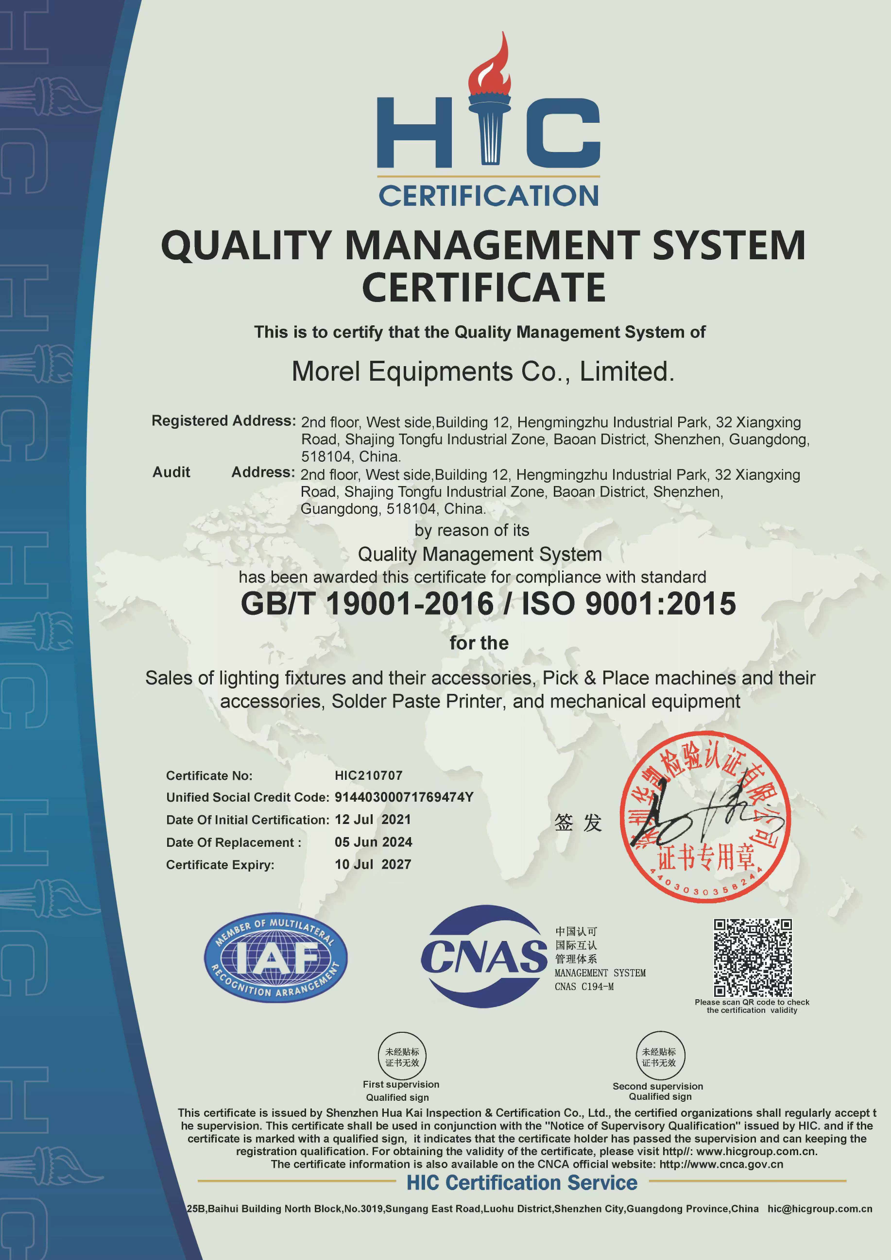
- ISO 9001:2015 / GB/T 19001-2016 quality management system certificate HIC210707, issued 12 July 2021 and valid to 10 July 2027 by Shenzhen Hua Kai Inspection & Certification Co., Ltd. The certified scope covers the sales of Pick & Place machines and their accessories, Solder Paste Printer, and mechanical equipment.
- EU Machinery Directive Attestation of Conformity M.2023.206.C91284, issued 11 October 2023 and valid to 10 October 2028 by UDEM International Certification Auditing Training Centre, assessed against 2006/42/EC Machinery Directive Annex VIII, EN 60204-1:2018, EN ISO 12100:2010 and EN 61010-1:2010+A1:2019.
For EU-bound shipments, Motek also holds German Packaging Act registration DE2364478064729, issued on 21 December 2022 by Stiftung Zentrale Stelle Verpackungsregister (ZSVR) for registration as a manufacturer of filled packaging under VerpackG § 9 / § 26.
On the product side, the assembly acceptance reference remains IPC-A-610J (released March 2024), the current global standard for the acceptability of electronic assemblies, which defines Class 1, 2 and 3 quality levels (IPC International).
FAQ
1. What certifications and compliance documents should a buyer expect with an SMT line?
A Motek SMT line is supported by an ISO 9001:2015 / GB/T 19001-2016 quality management system certificate (HIC210707, valid to 10 July 2027, covering the sales of Pick & Place machines and their accessories, Solder Paste Printer and mechanical equipment), an EU Machinery Directive Attestation of Conformity (M.2023.206.C91284, valid to 10 October 2028, assessed against 2006/42/EC, EN 60204-1:2018, EN ISO 12100:2010 and EN 61010-1:2010+A1:2019), and German Packaging Act registration DE2364478064729 issued by ZSVR. Assembly acceptability is benchmarked against IPC-A-610J, which defines Class 1, 2 and 3 quality levels.
2. Can one linked line handle both high-volume and mixed-product production?
Yes, within the machine envelope. The HMH830D dispensing stage stores more than 1000 running programs and uses manual teaching, so product changeover is a program recall rather than a mechanical reset. The dispensing stage accepts PCB widths of 50–450 mm and the Hanwha Decan S2 placement stage accepts PCBs from 50 × 40 mm to 510 × 460 mm (standard). Transfer direction is L→R (R→L), which keeps line layout flexible for different floor plans.
3. What are the commercial terms for a Motek SMT turnkey solution?
MOQ is 1 unit and lead time is 7–45 days, with a monthly capacity of 5,000 units. Delivery terms available are FOB, CIF, EXW, FCA, DDP and DAF. Payment terms are 30% T/T in advance with 70% T/T against copy of B/L, or 50% T/T in advance with 50% T/T against copy of B/L. Export markets served are the EU, US, Middle East and Southeast Asia.
4. How is the line validated before shipment, and what support follows?
The acceptance criterion is a pre-shipment test, and every unit passes 100% pre-shipment testing. Support includes remote technical support and 24/7 online service, with the option for the client to dispatch engineers to China for training of about one week. On-site training can also be arranged as part of the personalised service plan.
5. What is the delivery timeline, and what should a buyer prepare before ordering?
Lead time runs 7–45 days depending on configuration, against a monthly capacity of 5,000 units. Before ordering, a buyer should confirm the board width envelope (50–450 mm at dispensing; 50 × 40 mm to 510 × 460 mm at placement), the intended transfer direction (L→R or R→L), the number of product programs required, and the facility's exhaust capability for reflow, which is specified at 11 m³/min × 2. Motek also provides production line layout design and voltage, logo, packaging, colour, size, graphics and material customisation.
Conclusion
The transformation from three machines to one assembly process comes from a small number of decisions: keep the board on a conveyor, keep the transfer height fixed at a defined datum such as 920 ± 20 mm, match the cadence between dispensing at 0–5000 mm/min and placement at up to 92,000 CPH, and make batch changeover a program recall rather than a mechanical reset.
What that produces is measurable at the line level rather than the machine level: fewer handling steps, fewer opportunities for misalignment or re-orientation, shorter changeovers between products, and a flow that can serve high-volume and high-mix production on the same footprint. For buyers evaluating SMT turnkey solutions, the right question is no longer "how fast is each machine?" but "can these three machines be operated as one sequence?" That is the question a seamless dispensing-to-reflow flow answers.
Next Step: Review the Flow Against Your Own Product Mix
Send your board width range, batch profile and target output, and Motek will map the dispensing, placement and reflow configuration to it.
Email: sales@morequip.com | Tel: +86-755-21635007 | WhatsApp: +86 199 2455 0176
Website: www.morequip.com | Catalog: Download the Motek SMT catalog (PDF)
Motek — Morel Equipments Co., Ltd., Guangdong Shenzhen Baoan 405, Block A, Building 6, Exhibition Bay Zhonggang Plaza, No. 83 Zhancheng Road, Zhancheng Community, Fuhai Street.
Have Questions or Need More Details?
Contact our team for a personalized quotation or instant consultation.
Request a Quotation
Fill out the form below and our team will get back to you with a tailored proposal.
WhatsApp Direct Chat
Prefer to chat in real-time? Message us on WhatsApp for instant assistance & quick answers.
- Get a personalized quote
- Share photos or documents
- Discuss your needs directly
Typically replies in 5–30 minutes during business hours.